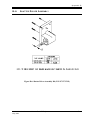
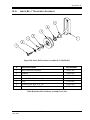
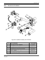
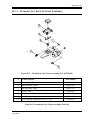
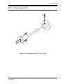
1
DIGITAL
SYSTEMS
Operating Instructions
For
CineX35
35mm Film Projector
Analog/Digital, Auto Turret Model CineX35-DAT(Z)
Analog, Auto-Turret Model CineX35-AT(Z)
Analog/Digital, Manual Turret Model CineX35-DM(Z)
Analog, Manual Turret Model CineX35-MT(Z)
115VAC, 60Hz Motor or 220VAC, 50Hz Motor
TD-747: Version 1.0
CHRISTIE DIGITAL SYSTEMS
10550 Camden Drive
Cypress, CA 90630
Tel: 714-236-8610 Fax: 714-503-3385
Operator’s Manual
CineX35-DMT(Z)/CineX35-DAT(Z)
CineX35-MT(Z)/CineX35-AT(Z)
TD-747
The information in this document is subject to change without notice and does not represent a
commitment on the part of CHRISTIE, DIGITAL SYSTEMS (hereinafter referred to as
CHRISTIE). CHRISTIE does not assume responsibility for errors that may appear in this
document. CHRISTIE or its subsidiaries, designated representatives, and any other vendor of
the CineX35 Film Projector are not responsible in any way for any liabilities or loss resulting
from the use or misuse of this document.
Copyright © 2004 by CHRISTIE, DIGITAL SYSTEMS
All Rights Reserved
Ultramittent© is a copyright of CHRISTIE, DIGITAL SYSTEMS.
All other copyrights and trademarks are the property of their respective owners.
CHRISTIE
DIGITAL SYSTEMS
10550 Camden Drive
Cypress, CA 90630
Telephone 714-236-8610
FAX 714-503-3385
TABLE OF CONTENTS
TABLE OF CONTENTS................................................................................i
LIST OF FIGURES AND TABLES..............................................................iv
1. INTRODUCTION .................................................................................. 1-1
1.1. Contents of the Manual.................................................................................................. 1-1
1.2. Who Should Use This Manual?..................................................................................... 1-1
1.3. Special Notices .............................................................................................................. 1-1
1.3.1. Warning .................................................................................................................. 1-2
1.3.2. Caution ................................................................................................................... 1-2
1.3.3. Note ........................................................................................................................ 1-2
2. General Description............................................................................ 2-1
2.1. Optional Features........................................................................................................... 2-1
2.2. Specifications................................................................................................................. 2-1
3. Projector installation and Assembly................................................. 3-1
3.1. Unpacking the Projector ................................................................................................ 3-1
3.2. Installation ..................................................................................................................... 3-1
3.3. Electrical Connections ................................................................................................... 3-3
3.3.1. Solar Cell Wiring.................................................................................................... 3-3
3.3.2. A-C Projector Wiring ............................................................................................. 3-5
4. OPERATING THE PROJECTOR ......................................................... 4-1
4.1. General........................................................................................................................... 4-1
4.2. Pre-Operating Procedures.............................................................................................. 4-1
4.2.1. Flywheel Installation .............................................................................................. 4-1
4.2.2. Lens Installation ..................................................................................................... 4-1
4.3. Film Threading and Operating Procedure ..................................................................... 4-2
5. MAINTENANCE ................................................................................... 5-1
5.1. General Maintenance ..................................................................................................... 5-1
5.2. Visual Inspection ........................................................................................................... 5-1
5.3. Cleaning......................................................................................................................... 5-2
5.4. Removal of Assemblies ................................................................................................. 5-2
5.4.1. Removal of the Trap and Gate Assembly............................................................... 5-2
5.4.2. Outer Belt ............................................................................................................... 5-3
5.4.3. Inner Belt ................................................................................................................ 5-3
5.4.4. Shutter Timing Belt ................................................................................................ 5-4
CHRISTIE DIGITAL SYSTEMS CineX35 Projector
May, 2004
i
Table of Contents
5.4.5. Ultramittent Assembly ........................................................................................... 5-6
5.4.6. Removal of Sound-head Assembly........................................................................ 5-6
5.4.7. Removal of Changeover Assembly........................................................................ 5-6
5.4.8. Removal of Shutter Driver Assembly .................................................................... 5-7
5.4.9. Removal of Motor Assembly ................................................................................. 5-7
5.4.10. Removal of Framing Lamp .................................................................................... 5-7
6. CALIBRATION, ALIGNMENT, AND ADJUSTMENT PROCEDURES. 6-1
6.1. Analog Reader Alignment and Adjustments................................................................. 6-1
6.1.1. Preliminary Procedures .......................................................................................... 6-2
6.1.2. Cell Positioning: Vertical Alignment..................................................................... 6-2
6.1.3. Horizontal (Lateral) Alignment ............................................................................. 6-2
6.1.4. Focus and Azimuth ................................................................................................ 6-2
6.1.5. Alignment Verification .......................................................................................... 6-2
6.1.6. Performance Check: Crosstalk.............................................................................. 6-3
6.1.7. Illumination Uniformity ......................................................................................... 6-3
6.1.8. Final Check ............................................................................................................ 6-3
6.2. Digital Reader Alignment ............................................................................................. 6-3
6.2.1. Preliminary Steps ................................................................................................... 6-3
6.2.2. Alignment Procedure ............................................................................................. 6-4
6.3. Dashpot Adjustment ...................................................................................................... 6-5
6.4. Inner, Outer, and Shutter Timing Belt Adjustment....................................................... 6-5
6.4.1. Inner Belt................................................................................................................ 6-5
6.4.2. Shutter Timing Belt................................................................................................ 6-5
6.4.3. Outer Belt ............................................................................................................... 6-6
6.5. Shutter Timing............................................................................................................... 6-6
6.6. The CHRISTIE Lens Turret .................................................................................... 6-7
6.6.1. General Description ............................................................................................... 6-7
6.6.2. The Manual Turret System .................................................................................... 6-7
6.6.3. The Automatic Turret System................................................................................ 6-7
6.6.4. Timing Adjustments – Turret and Aperture Motor................................................ 6-8
6.7. Optical Image Alignment and Adjustment Procedures................................................. 6-9
7. Troubleshooting Procedures ............................................................. 7-1
7.1. Motor............................................................................................................................. 7-1
7.1.1. SYMPTOM: Motor Not Working......................................................................... 7-1
7.2. Ultramittent Assembly .................................................................................................. 7-2
7.2.1. SYMPTOM: Excessive Ticking ........................................................................... 7-2
7.2.2. SYMPTOM: Excessive Film Noise ...................................................................... 7-2
7.2.3. SYMPTOM: Film Instability (Jump).................................................................... 7-2
7.2.4. SYMPTOM: Shutter Streaking............................................................................. 7-2
7.3. Constant-Speed Sprocket (Main frame Assembly)....................................................... 7-2
7.3.1. SYMPTOM: Excessive Noise .............................................................................. 7-2
7.3.2. SYMPTOM: Film Sprocket Hole Damage ........................................................... 7-2
7.3.3. SYMPTOM: Sprocket Riding............................................................................... 7-2
7.4. Belts............................................................................................................................... 7-3
7.4.1. SYMPTOM: Excessive Noise .............................................................................. 7-3
CHRISTIE DIGITAL SYSTEMS CineX35 Projector
May, 2004
ii
Table of Contents
7.4.2. SYMPTOM: Excessive Belt Dust ......................................................................... 7-3
7.4.3. SYMPTOM: Excessive Belt Failure ..................................................................... 7-3
7.5. Changeover Assembly ................................................................................................... 7-3
7.5.1. SYMPTOM: Operating Inconsistently.................................................................. 7-3
7.5.2. SYMPTOM: Not Operating .................................................................................. 7-3
7.6. Shutter Driver and Jackshaft System............................................................................. 7-3
7.6.1. SYMPTOM: Excessive Noise............................................................................... 7-3
7.6.2. SYMPTOM: Shutter Streak .................................................................................. 7-4
7.7. Trap and Gate Assembly ............................................................................................... 7-4
7.7.1. SYMPTOM: Excessive Jump and Weave............................................................. 7-4
7.7.2. SYMPTOM: Aperture Binding ............................................................................. 7-4
7.8. Lens Turret..................................................................................................................... 7-4
7.8.1. SYMPTOM: Not Rotating .................................................................................... 7-4
7.8.2. SYMPTOM: Focus Knob Inoperative................................................................... 7-4
7.8.3. SYMPTOM: Turret Hinge Too Loose or too tight ............................................... 7-4
Appendix A: Replaceable Assemblies and Components.....................1
Appendix B: Diagrams and Parts Lists..................................................1
B-1: Light Baffle and Changeover Assembly....................................................................... B-2
B-2: Trap and Gate Assembly .............................................................................................. B-3
B-3: Fixed Idler Assembly.................................................................................................... B-6
B-4: Jackshaft Assembly ...................................................................................................... B-7
B-5: Main Frame Assembly.................................................................................................. B-9
B-6: Shutter Driver Assembly ............................................................................................ B-11
B-7: Outer Belt Tensioner Assembly.................................................................................. B-12
B-8: Inner Belt Tensioner Assembly .................................................................................. B-13
B-9: Soundhead Assembly.................................................................................................. B-14
B-10: Idler Roller Assembly................................................................................................. B-16
B-11: Ultramittent Shoe Closure Assembly ......................................................................... B-17
B-12: Single Blade Shutter Assembly .................................................................................. B-18
B-13: Framing Knob Kit....................................................................................................... B-19
Appendix c: SCHEMATIC Diagrams .........................................................1
INDEX ..........................................................................................................3
CHRISTIE DIGITAL SYSTEMS CineX35 Projector
May, 2004
iii
Table of Contents
LIST OF FIGURES AND TABLES
Figure 2-1: Table of Equipment Specifications........................................................................... 2-1
Figure 2-2: Projector, Front View ............................................................................................... 2-2
Figure 2-3: Projector, Rear View ................................................................................................ 2-3
Figure 2-4: Projector.................................................................................................................... 2-5
Figure 3-1: Installing the Projector.............................................................................................. 3-2
Figure 3-2: Tools and Materials Required for Assembly and Maintenance................................ 3-3
Figure 3-3: Projector Wiring Diagram (50- and 60-Hz models) ................................................. 3-4
Figure 3-4: Table of A-C Terminal Connections ........................................................................ 3-5
Figure 4-1: Threading Diagram ................................................................................................... 4-3
Figure 5-1: Schedule for Periodic Maintenance Operations ...................................................... 5-1
Figure 5-2: Outer Belt.................................................................................................................. 5-3
Figure 5-3: Inner Belt .................................................................................................................. 5-4
Figure 5-4: Shutter Timing Belt .................................................................................................. 5-5
Figure 6-1: Analog Reader Assembly ......................................................................................... 6-1
Figure 6-2: Digital Reader Assembly .......................................................................................... 6-4
Figure 6-3: Lens Turret (Front View).......................................................................................... 6-7
Figure 6-4: Lens Turret (Rear View).......................................................................................... 6-8
Table A-1: CineX35 Projector Replaceable Assemblies and Components................................ A-2
Figure B-1: Light Baffle and Changeover ...................................................................................B-2
Table B-1: Light Baffle and Changeover Assembly Parts List ...................................................B-2
Figure B-2: Trap and Gate Assembly (P/N 197552-001)............................................................B-3
Table B-2: Trap and Gate Assembly Parts List ..........................................................................B-5
Figure B-3: Fixed Idler Assembly (P/N 194879-001)................................................................B-6
Table B-3: Fixed Idler Roller Assembly Part List.......................................................................B-6
Figure B-4: Jackshaft Assembly (P/N 197551-001)....................................................................B-7
Table B-4: Jackshaft Assembly Parts List ..................................................................................B-8
Figure B-5: Main Frame Assembly (P/N 197560-001)...............................................................B-9
Table B-5: Main Frame Assembly Parts List ............................................................................B-10
Figure B-6: Shutter Driver Assembly (P/N 197137-XXX).......................................................B-11
Figure B-7: Outer Belt Tensioner Assembly (P/N 197583-001)..............................................B-12
Table B-7: Outer Belt Tensioner Assembly Parts List ..............................................................B-12
Figure B-8: Inner Belt Tensioner Assembly (P/N 196056-001) ...............................................B-13
Table B-8: Inner Belt Tensioner Assembly Parts List...............................................................B-13
Figure B-9: Soundhead Assembly (P/N 197510-001)...............................................................B-14
Table B-9: Soundhead Assembly Parts List .............................................................................B-15
Figure B-10: Idler Roller Assembly (P/N 194782-001) ............................................................B-16
Table B-10: Idler Roller Assembly Parts List ...........................................................................B-16
Figure B-11: Ultramittent Shoe Closure Assembly (P/N 197578-001) ...................................B-17
Table B-11 Ultramittent Shoe Closure Assembly Parts List .....................................................B-17
Figure B-13: Single Blade Shutter Assembly (P/N 194697-XXX)..........................................B-18
Figure B-13: Framing Knob Kit (P/N 197131-001) .................................................................B-19
CHRISTIE DIGITAL SYSTEMS CineX35 Projector
May, 2004
iv
1
1. INTRODUCTION
1.1.
CONTENTS
OF THE
MANUAL
This manual contains installation, operation, and operator maintenance procedures for
CHRISTIE CineX35 film Projector models. The material covered includes:
•
•
•
•
•
•
general description
installation and assembly
operating the projector
periodic maintenance
calibration, alignment, and adjustments
troubleshooting.
1.2.
WHO SHOULD USE THIS MANUAL?
This manual provides information suitable for various purposes. For details on operating the
projector and for general information, see:
• Section 2: General Description
• Section 3: Installation and Assembly
• Section 4: Operating the Projector.
Before performing adjustments and periodic maintenance during normal operation, see:
• Section 5: Periodic Maintenance
• Section 6: Calibration, Alignment, and Adjustments.
If a problem occurs, see:
• Section 7: Troubleshooting Procedures.
Additional reference information is contained in the appendices.
1.3.
SPECIAL NOTICES
Three kinds of specific notices are used within this manual to emphasize specific
information.
CHRISTIE DIGITAL SYSTEMS CineX35 Projector
May, 2004
1-1
1:
1.3.1.
Introduction
WARNING
WARNING: Indicates the presence of a hazard that can cause personal
injury if the hazard is not avoided.
WARNING
1.3.2.
CAUTION
CAUTION: Indicates the presence of a hazard that could cause damage
to projection system.
1.3.3.
NOTE
NOTE: Provides additional information.
CHRISTIE DIGITAL SYSTEMS CineX35 Projector
May, 2004
1-2
2
2.
GENERAL DESCRIPTION
The CHRISTIE CineX35 film Projector, manufactured exclusively by CHRISTIE
DIGITAL SYSTEMS is a dual-lens 35mm motion-picture projector that employs a
revolutionary sealed-bearing intermittent movement called the Ultramittent©. This
movement coupled with uncompromising design and assembly workmanship, results in the
finest possible theater picture reproduction. The Ultramittent movement is standard on all
CHRISTIE projectors.
2.1.
OPTIONAL FEATURES
Options available for enhancing the standard features of the CineX35 projector include:
• manual dual-lens turret
• automatic dual lens turret, including automatic aperture changer
• inboard Dolby digital reader
• all models available in 50 Hz or 60 Hz
2.2.
SPECIFICATIONS
Standard specifications for the CineX35 projector family are listed in the Table shown in
Figure 2-1, below.
POWER REQUIREMENTS:
Input Voltage
OR
115 VAC, 5 Amp, 60 Hz
220 VAC, 3 Amp, 50 Hz
DIMENSIONS:
Height
Width
Depth
WEIGHT:
FILM SPEED:
OPERATING TEMPERATURE:
MOTOR:
OR
23 inches
17 inches
21 inches (with motor)
88 lb. (40 kg)
Standard: 24 frames/sec (90 ft/min)
0 to +45°C
Synchronous split phase, 1800 rpm, 60 Hz
1500 rpm, 50 Hz
Figure 2-1: Table of Equipment Specifications
These specifications may vary slightly, depending upon the particular model and options
chosen.
CHRISTIE DIGITAL SYSTEMS CineX35 Projector
May, 2004
2-1
2:
1.
2.
3.
4.
5.
6.
Door, Framing Lamp (197576-001
Trap and Gate Assembly (197552-001)
Ultramittent Assembly (119450-005)
Ultramittent Shoe Closure (197578-001)
Door, Sound Readers (197549-001)
Sound Head Assembly (197510-001)
7.
8.
9.
10.
11.
General Description
Main Frame Assembly (197560-001)
Shutter Belt Cover (194600-001)
Basic Turret Assembly (197100-100)
Switch, Flat-Scope (578900-040)
Switch, Framing Lamp (578900-042)
Figure 2-2: Projector, Front View
CHRISTIE DIGITAL SYSTEMS CineX35 Projector
May, 2004
2-2
2:
12. Motor Assembly 60-Hz (197553-001)
Motor Assembly 50-Hz (197553-002)
13. Idler Roller Assembly (194879-001)
14. Shutter Drive Assembly (197137-XXX)
15. Pulley 30 Grooves, Ultramittent (197516-001)
16. Power Supply Assembly, Sound-Head (197090001)
17. Flywheel, Sound Drum (119166-001)
18. Shaft, Sound Drum (196315-001)
General Description
19. Terminal Block Euro 10MM (586210008)
20. Jackshaft Assembly (197551-001)
21. Outer Belt Tensioner (197583-001)
22. Light Baffle & Changeover (197550-001)
23. Pulley, 48 Grooves (2 PLS) (197517-001)
24. Belt 5MR-1050 (2 PLS) (598931-177)
25. Turret Auto Control, Option (197580-001)
Figure 2-3: Projector, Rear View
CHRISTIE DIGITAL SYSTEMS CineX35 Projector
May, 2004
2-3
2:
CHRISTIE DIGITAL SYSTEMS CineX35 Projector
May, 2004
General Description
2-4
2:
26. Dual LED Regulator (197084-001)
27. Harness (197080-001)
General Description
28. Fuse 1A, 250V, SLO-BLO (546101-012)
Figure 2-4: Projector
CHRISTIE DIGITAL SYSTEMS CineX35 Projector
May, 2004
2-5
3
3.
PROJECTOR INSTALLATION AND
ASSEMBLY
3.1.
UNPACKING
THE
PROJECTOR
Before opening box (es), carefully inspect outside of carton(s). If carton
has been damaged, notify shipper immediately; do not open carton
unless instructed to do so.
The CHRISTIE projector may be shipped in more than one container. Each projector
normally comes complete with the following items:
• dual aperture plate (shipped in place)
•
•
•
•
•
•
framing lamp (installed)
sound-head flywheel (not installed)
sound-head assembly (factory-aligned)
dual-lens turret
drive motor assembly
instruction manual.
The console and projector are shipped in a single carton, with special pockets containing
smaller items. Sound-head flywheel are shipped separately.
To unpack:
1. Open carton(s).
2. Remove all protective material from framing lamp, sound-head assembly, and lens
holder.
3. Remove protective material around side panel.
3.2.
INSTALLATION
To install the projector, refer to Figure 3-1. The required materials and tools for installing
and assembling the projector are outlined in the Table in Figure 3-2.
1. Loosen but do not remove nut on projector mounting stud (item 4 in Figure 3-1). Verify
that lock washer (item 5 in Figure 3-1) and flat washer (item 6 in Figure 3-1) are
correctly positioned on mounting stud. Flat washer should be next to lock washer,
followed by nut.
CHRISTIE DIGITAL SYSTEMS CineX35 Projector
May, 2004
3-1
3:
Projector Installation and Assembly
2. Insert lock washer (item 2 in Figure 3-1) and flat washer (item 3 in Figure 3-1) onto hex
bolt (item 1 in Figure 3-1). Insert hex head bolt, with lock washer and flat washer, into
upper left opening of projector mount. Rotate hex head bolt four full turns.
3. Lift and mount projector to console or pedestal. Thread two remaining hex head bolts
with lock washer and flat washer. Insert into two bottom mounting holes on projector.
4. Level projector on lamp-house or pedestal.
5. Tighten nut on mounting stud using 9/16" wrench.
6. Tighten three hex head bolts using same wrench.
Figure 3-1: Installing the Projector
CHRISTIE DIGITAL SYSTEMS CineX35 Projector
May, 2004
3-2
3:
Category
Tools
Projector Installation and Assembly
Item
Use
Miscellaneous Allen wrenches General Maintenance
Small standard screwdriver
Phillips screwdrivers
Equipment
Materials
Oscilloscope
Voltmeter
Real-time Analyzer
SK1994-3 alignment tool
Sound-head Alignment
P35-BT (SMPTE)
Buzz Track Test Loop
P35-FL
Cat 69 Loop
Flutter Loop
Dolby Tone, Pink Noise
Cat 566 Loop
Cat 97 Loop
RP-40 Loop
Illumination Uniformity
Left/Right Alignment
Optical Alignment
Lateral Guide Alignment
Figure 3-2: Tools and Materials Required for Assembly and Maintenance
3.3.
ELECTRICAL CONNECTIONS
Before wiring the projector, refer to Figure 3-3 for the wiring interface diagram. Use
stranded wire. Strip and tin the wire prior to connection. Use crimp connectors on all sound
connections. For projectors equipped with an automatic turret, refer to Section 6.6.3.
3.3.1.
SOLAR CELL WIRING
Solar cell wiring requires a shielded, four-conductor audio cable. (red – left (+), black – left
(-), green – right (+), white – right (-)). The best signal-to-noise ratio is achieved by
maintaining the same ground potential between the sound-head and the cinema processor.
Refer to the directions in the sound system instruction manual for proper connection of the
sound system.
CHRISTIE DIGITAL SYSTEMS CineX35 Projector
May, 2004
3-3
3:
Projector Installation and Assembly
Figure 3-3: Projector Wiring Diagram (50- and 60-Hz models)
CHRISTIE DIGITAL SYSTEMS CineX35 Projector
May, 2004
3-4
3:
3.3.2.
Projector Installation and Assembly
A-C PROJECTOR WIRING
AC wiring to the projector requires stranded, 14-gauge wire. Be sure to follow local and
national electrical codes for A-C wiring. The terminal connection numbers in the table in
Figure 3-4 refer to terminals TB-1 in Figure 3-3.
Terminal TB1 Connection
A
Power Supply (AC-hot)
B
Power Supply (AC- neutral)
W1
Motor (AC neutral)
W3
Motor switch lead (AC hot, switched externally)
W4
Cooling Fan, Turret Control (AC-hot)
W5
Douser coil CLOSE (AC-hot switched externally)
W6
Douser coil OPEN (AC-hot switched externally)
J
Cooling Fan, Turret Control and Douser (AC neutral).
Figure 3-4: Table of A-C Terminal Connections
The voltage and frequency rating of the projector (shown on the
nameplate) must match the power line frequency and voltage being
used.
CHRISTIE DIGITAL SYSTEMS CineX35 Projector
May, 2004
3-5
4
4.
OPERATING THE PROJECTOR
4.1.
GENERAL
Before operating the projector, verify that all phases of installation and assembly have been
completed.
•
•
WARNING
•
Verify that cover for belt side of projector is installed before and
during operation.
Do not make adjustments on belt side of projector while cover is
removed and power is on.
Do not make adjustments or perform maintenance on projector
while it is in operation.
4.2.
P R E -O P E R A T I N G P R O C E D U R E S
4.2.1.
FLYWHEEL INSTALLATION
1. Back out flywheel set screw far enough to let flywheel slide onto shaft without scoring
shaft or damaging threads on set screw.
2. Slide flywheel onto shaft until it stops.
3. Position set screw over flat portion of shaft and tighten set screw.
4. Spin flywheel by hand to check for smooth operation.
CHRISTIE recommends that any projector accessories be installed at
this time.
4.2.2. LENS INSTALLATION
1. Install lens system in lens holder. If it is necessary to open lens holder wider than
normal:
a) Loosen two lens-locking screws.
b) Turn jack screw clockwise until lens slides into lens holder; turn the screw back.
2. Set focus knob at mid-position.
CHRISTIE DIGITAL SYSTEMS CineX35 Projector
May, 2004
4-1
4:
Operating the Projector
3. Secure lens system with two locking screws.
Over-tightening can cause focus mechanism to bind.
4.3.
FILM THREADING
AND
OPERATING PROCEDURE
Refer to Figure 4-1 for film threading and positioning using flywheel.
1. Set Ultramittent to its rest position. There should be no sprocket movement when motor
flywheel is turned.
2. Center framing knob (P) by aligning mark on knob with line on projector housing marked
CENTER FRAME.
3. Swing out pad rollers (B, F, L) on constant-speed sprockets (A & G).
4. Swing out film shoe on Ultramittent assembly (E).
5. Pull out catch knob (D) and swing out gate assembly (C).
6. Using slightly more film length than is required to reach film transport system, begin to
thread film into projector.
7. Align film on Ultramittent sprocket and close Ultramittent film shoe.
8. To form proper loop between Ultramittent and lower constant-speed sprocket:
a) Pull film loosely over lower constant-speed sprocket, form loop as shown on Figure
4-1.
b) Mate film sprocket holes with sprocket pins.
c) Hold film in position and close pad rollers.
9. Thread film on sound-head assembly as shown in Figure 4-1:
a) Holding two lateral guide rollers (H and K) towards each other, pull film tight and
align film on lower constant-speed sprocket assembly (G).
b) Tighten film on one sprocket hole so lateral guides barely float off sound drum.
c) Close pad rollers (L) of lower constant-speed sprocket.
CHRISTIE DIGITAL SYSTEMS CineX35 Projector
May, 2004
4-2
4:
A:
B:
C:
D:
E:
F:
Upper Constant Speed Sprocket
Pad Rollers, Upper Speed Sprocket
Gate Assembly
Catch knob
Ultramittent Shoe Assembly
Pad Rollers, Lower Constant Speed Sprocket
G:
H:
J:
K:
L:
P:
Operating the Projector
Lower Constant Speed Sprocket
Lateral Guide Roller (Upper)
Sound Drum
Lateral Guide Roller (Lower)
Pad Rollers, Lower Constant Speed Sprocket
Framing Knob
Figure 4-1: Threading Diagram
CHRISTIE DIGITAL SYSTEMS CineX35 Projector
May, 2004
4-3
4:
Operating the Projector
10. Form 1.75-inch loop between upper constant-speed sprocket and gate (C), as shown in
Figure 4-1
11. Align the film on upper constant-speed sprocket (A) and close pad rollers (B).
12. To verify that film is correctly aligned on all sprocket rollers, move motor flywheel
counterclockwise.
•
•
•
Framing lamp can be turned “on” or “off” with black rocker switch
located on top of projector.
Framing lamp is functional with picture changeover in either
position.
If film reel is used, be sure take-up tension is in accordance with reel
manufacturer’s instructions.
CHRISTIE DIGITAL SYSTEMS CineX35 Projector
May, 2004
4-4
5
5.
MAINTENANCE
This projector has been designed to provide years of optimum performance while requiring
only routine maintenance and cleaning. However, CHRISTIE strongly recommends a
periodic maintenance program of scheduled operational checks and preventive maintenance.
5.1.
GENERAL MAINTENANCE
Use the program outlined in the schedule in Figure 5-1 to maximize projector life and
operating efficiency. Procedures for these operations are described in the referenced sections
of this manual.
Frequency
Maintenance Operation
Section
Daily
Visual inspection
5.2
Daily
Clean projector
5.3
Bi-weekly
Oil lateral guides and jewels
5.3
Annually
Replace belts* and blow out belt dust
5.4.2
Figure 5-1: Schedule for Periodic Maintenance Operations
* If Necessary
5.2.
VISUAL INSPECTION
1. Visually inspect projector for signs of excessive dust, dirt, physical damage, frayed or
damaged cables, and loose hardware.
2. Remove, replace, and repair as necessary.
3. Visually inspect inner, outer, and shutter timing belts. Replace belts that are frayed or show
signs of wear.
4. Check belt tension (Sections 6.4.1, 6.4.2, and 6.4.3) and re-adjust if necessary.
Ultramittent should be visually checked every 30 days. If leak is
detected, contact CHRISTIE to arrange for loan of substitute
Ultramittent. If leak is very slow, you may continue to operate
Ultramittent for 30 to 90 days.
CHRISTIE DIGITAL SYSTEMS CineX35 Projector
May, 2004
5-1
5:
5.3.
Maintenance
CLEANING
Projector should be kept clean at all times.
1. Remove dust and foreign matter from projector and assemblies. Use soft, lint-free cloth, or
spray with compressed air at force no greater than 20 psi.
2. Using camelhair brush or toothbrush, remove dust and foreign matter from pad rollers,
sprockets, Ultramittent shoe closure, and sound idler rollers, and from pads and shoes in trap
and gate assembly.
3. Using cotton-tip swabs, remove dirt and dust from sound-head optics.
4. Lightly oil lateral guide rollers and springs with very fine machine oil (trap and gate). Inner
flange of lateral guide should move easily and should spring back to rest position without
sticking.
Do not adjust lateral guides without proper alignment tool (SK1994-3).
5.4.
REMOVAL
OF
ASSEMBLIES
The following sections contain instructions and procedures necessary to remove assemblies
and components from the projector. Use only the specified tools to perform these
procedures. The use of any other tools will cause damage to the assemblies and components.
Appendix A contains a list of replaceable assemblies and components and their part numbers.
Removal and replacement of the assemblies discussed in Sections 5.4.1 through 5.4.10 may
be performed by the customer. The customer may also repair broken leads, solder
connections. All other repairs and replacements are to be performed only by an authorized
service representative. In general, any problem that does not appear to be treatable by a
minor procedure should be treated by removing the defective assembly and returning it to
CHRISTIE for repair.
5.4.1.
REMOVAL
OF THE
TRAP
AND
GATE ASSEMBLY
Refer to item 2 in Figure 2-2 on page 2-2.
1. Open trap and gate assembly by pulling catch knob.
2. Remove two socket head cap screws securing assembly to mainframe.
3. Remove assembly by gently pulling free from locating pins.
CHRISTIE DIGITAL SYSTEMS CineX35 Projector
May, 2004
5-2
5:
5.4.2.
Maintenance
OUTER BELT
Refer to Figure 5-2 below.
1. Loosen outer belt tensioner screw (item 7 in Figure 5-2) and slide roller (item 8 in Figure
5-2) up to release tension on outer belt (item 1 in Figure 5-2).
2. Remove outer belt.
1: Outer Belt
(598931-177)
2: Roller, Idler
(194782-001)
3: Motor Pulley
(197514-001 60Hz)
(197514-002 50Hz)
4: Large Pulley
(60teeth)
(197518-001)
5: Jackshaft Pulley
(197513-001)
6: Outer Belt Tensioner
(197583-001)
7: Locking Screw, Outer
Belt Tensioner
(515500-105)
8: Roller, Outer Belt
Tensioner
(194782-001)
9: Shutter Drive Assy
See Figure B-6
(197137-XXX)
10: Ultramittent Pulley
(197516-001)
Figure 5-2: Outer Belt
5.4.3.
INNER BELT
Refer to Figure 5-3 below.
1. Remove outer timing belt (see Section 5.4.2).
2. Loosen inner belt tensioner screw (item 3 in Figure 5-3).
3. Remove inner timing belt (item 1 in Figure 5-3).
CHRISTIE DIGITAL SYSTEMS CineX35 Projector
May, 2004
5-3
5:
Maintenance
1: Inner Belt
(598931-177)
2: Roller, Inner Belt
Tensioner
(194782-001)
3: Locking Screw, Inner
Belt Tensioner
(515500-105)
4: Inner Belt Tensioner
(196056-001)
5: Sprocket Pulley
(Upper and Lower)
(197517-001)
6: Small Pulley
(16teeth)
(197512-001)
7: Shutter Drive Assy
See Figure B-6
(197137-XXX)
Figure 5-3: Inner Belt
5.4.4.
SHUTTER TIMING BELT
Refer to Figure 5-4 below.
1. Remove trap and gate assembly (refer to Section 5.4.1)
2. Remove shutter belt cover (item 8 refer to Figure 2-2 on page 2-2).
3. Loosen three Allen head screws securing jack-shaft assembly to mainframe (item 5 in
Figure 5-4) from non-operating side of projector.
4. Pull jack-shaft assembly down approximately 0.5 inch.
5. Remove shutter timing belt (item 1 in Figure 5-4).
CHRISTIE DIGITAL SYSTEMS CineX35 Projector
May, 2004
5-4
5:
Maintenance
1: Shutter Timing Belt
(598931-533)
2: Pulley (Shutter Dr.)
(194827-001)
3: Housing, Shutter Dr.
(194915-001)
4: Single Blade Shutter
Assy (194697-XXX)
See Figure B-12
5: Housing Jackshaft
(196469-001)
6: Pulley (Jackshaft)
(194824-001)
7: Screw, SHC 6-32x1/2
(598931-042)
Figure 5-4: Shutter Timing Belt
CHRISTIE DIGITAL SYSTEMS CineX35 Projector
May, 2004
5-5
5:
5.4.5.
Maintenance
ULTRAMITTENT ASSEMBLY
Disassembly of Ultramittent or attempted repair of components will
void warranty.
Refer to item 3 in Figure 2-2 on page 2-2.
1. Relieve tension on outer timing belt (see Section 5.4.2).
2. Remove two Allen head screws securing Ultramittent shoe.
3. Remove Ultramittent shoe closure assembly (item 4 in Figure 2-2 on page 2-2)
4. Remove four Allen head screws and washers securing Ultramittent assembly to
Ultramittent plate.
5. Carefully slide Ultramittent assembly out from non-operating side of projector.
5.4.6.
REMOVAL
OF
SOUND-HEAD ASSEMBLY
Refer to item 6 in Figure 2-2 and Figure 2-3.
1. Remove flywheel sound drum (item 17 in Figure 2-3).
2. Open door of sound readers, which is secured by two quarter-turn fasteners (item 5 in
Figure 2-2).
3. Disconnect LED leads at Dual LED Regulator.
4. Disconnect analog reader assembly connector.
5. Disconnect Video cable from digital reader assembly.
6. Remove four Allen screws in corners of base plate sound head.
7. Remove sound head assembly.
5.4.7.
REMOVAL
OF
CHANGEOVER ASSEMBLY
Refer to item 22 in Figure 2-3 and Figure B-1.
1. Carefully pull four quick connect lugs from changeover solenoids (item 9 in Figure B-1).
2. Open framing lamp door (item 1 in Figure 2-1), which is secured by two quarter-turn
fasteners.
3. Unscrew knob changeover (douser).
4. Remove four Allen screws (item 14 in Figure B-1) (which holds changeover assembly)
through holes in light baffle assembly (item 1 in Figure B-1).
5. Remove changeover assembly out from non-operating side of the projector.
CHRISTIE DIGITAL SYSTEMS CineX35 Projector
May, 2004
5-6
5:
5.4.8.
REMOVAL
OF
Maintenance
SHUTTER DRIVER ASSEMBLY
Refer to item 7 in Figure 5-3: Inner Belt on page 5-4.
1. Relieve tension on outer belt (Section 5.4.2).
2. Relieve tension on inner belt (Section 5.4.3).
3. Relieve tension on shutter timing belt (Section 5.4.4).
4. Remove four Allen head screws securing shutter driver assembly.
5. Remove shutter driver assembly.
5.4.9.
REMOVAL
OF
MOTOR ASSEMBLY
Refer to item 12 in Figure 2-3 on page 2-3.
1. Disconnect motor's electrical leads at terminal block TB1-1 (item 19 Figure 2-3).
2. Relieve tension on outer timing belt (Section 5.4.2).
3. Remove cable ties holding motor cable in place by removing Allen head cap screws.
4. Remove four Allen head screws securing mounting plate with motor to motor bracket.
5. Remove motor assembly.
5.4.10. REMOVAL
OF
FRAMING LAMP
1. Open framing lamp door, which is secured by two quarter-turn fasteners (item 1 in Figure
2-2 on page 2-2).
2. Remove lamp as with ordinary light bulb.
CHRISTIE DIGITAL SYSTEMS CineX35 Projector
May, 2004
5-7
6
6.
CALIBRATION, ALIGNMENT, AND
ADJUSTMENT PROCEDURES
The projector has been factory aligned, calibrated, and adjusted prior to shipment. The
following paragraphs contain the necessary information to calibrate, align, and adjust the
various components and assemblies. Always observe standard safety precautions and
maintenance procedures when working on the projector.
6.1.
ANALOG READER ALIGNMENT
AND
ADJUSTMENTS
Refer to Figure 6-1 for these procedures.
1: Clamp Mounting
2: Focus Adjustment
3: Vertical Adjustment
Locking Screw
4: Azimuth Adjustment
Locking Screw
5: Horizontal Adjust.
6: Azimuth Adjustment
7: Horizontal Adjust.
Locking Screw
8: Vertical Adjustment
9: Focus Adjustment
Locking Screw
Figure 6-1: Analog Reader Assembly
CHRISTIE DIGITAL SYSTEMS CineX35 Projector
May, 2004
6-1
6:
6.1.1.
Calibration, Alignment, and Adjustment Procedures
PRELIMINARY PROCEDURES
Refer to Figure 3-2 on page 4 for a list of the tools, equipment, and materials required.
1. Verify that LED is operational and lens is clean.
2. Verify cell wiring for proper left/right wiring to cinema processor.
6.1.2. CELL POSITIONING: VERTICAL ALIGNMENT
1. Loosen 10-32-inch Allen set screw on side of assembly (item 3 in Figure 6-1).
2. Run Dolby Cat. 69 tone.
3. Adjust vertical position of cell (item 8 in Figure 6-1) for maximum output level.
4. Tighten locking screw on side of cell adjustment assembly. (Item 3 in Figure 6-1).
5. Adjust cinema processor's pre-amplifier gains for left and right tone reference levels.
6.1.3.
HORIZONTAL (LATERAL) ALIGNMENT
1. Loosen 10-32 Allen locking screw on bottom of cell adjustment assembly (item 7 in
Figure 6-1).
2. Run Buzz Track film.
3. Adjust lateral position of cell (item 5 in Figure 6-1) until there is no output at processor's
test points. If output is present on both left and right test points, increase focal distance
between lens and cell.
4. Tighten locking screw on bottom of cell adjustment assembly. (item 7 in Figure 6-1).
6.1.4.
FOCUS
AND
AZIMUTH
1. Loosen 10-32 Allen locking screw in hole on side assembly (item 4 in Figure 6-1).
2. Turn cinema processor's pre-amplifier Hf adjustments counterclockwise to minimum
settings.
3. Run Dolby Cat. 69 Pink Noise film (not older than 1992).
4. Adjust Focus (item 2 in Figure 6-1) and Azimuth (item 6 in Figure 6-1) for maximum
high frequency response and phase coherence.
5. Carefully lock focus adjustment (9) and azimuth set screw (4).
6. Turn cinema processor's pre-amplifier Hf adjustments clockwise until real-time analyzer
shows flat frequency response to 16 kHz.
7. Verify that both channels have identical frequency response.
6.1.5.
ALIGNMENT VERIFICATION
1. Repeat vertical and horizontal alignment procedures described in Sections 6.1.2 and
6.1.3.
CHRISTIE DIGITAL SYSTEMS CineX35 Projector
May, 2004
6-2
6:
Calibration, Alignment, and Adjustment Procedures
2. Recheck to verify that optimum alignment has been achieved.
6.1.6.
PERFORMANCE CHECK: CROSSTALK
1. Run Dolby Cat. 97 cell alignment film.
2. Verify that there is no crosstalk between left and right processor test points.
6.1.7.
ILLUMINATION UNIFORMITY
1. Run Dolby Cat. 566 illumination uniformity film.
2. Connect left and right processor test points.
3. Verify that illumination uniformity across cell is within ±0.5 dB.
6.1.8.
FINAL CHECK
1. Verify Dolby tone reference levels.
2. Run Buzz Track film.
3. Verify frequency response and azimuth.
4. Check that all locking adjustments screws are tight.
Repeat appropriate procedures from Sections 6.1.2 through 6.1.7 if adjustments are
necessary.
6.2.
DIGITAL READER ALIGNMENT
The polarity of visible red LEDs may be opposite from that of infrared
LEDs.
6.2.1.
PRELIMINARY STEPS
1. Turn LED power supply down (CCW) to minimum.
2. Connect video cable to Digital Reader Assembly.
3. Turn on digital processor.
4. Apply AC power to projector and verify that LEDs are operational.
CHRISTIE DIGITAL SYSTEMS CineX35 Projector
May, 2004
6-3
6:
Calibration, Alignment, and Adjustment Procedures
1: Clamp Mounting
2: Focus Adjustment
3: Vertical Adjustment
Locking Screw
4: Azimuth Adjustment
Locking Screw
5: Horizontal Adjust.
6: Azimuth Adjustment
7: Horizontal Adjust.
Locking Screw
8: Vertical Adjustment
9: Focus Adjustment
Locking Screw
Figure 6-2: Digital Reader Assembly
6.2.2.
ALIGNMENT PROCEDURE
1. Remove analog reader assembly, or rotate assembly downward, for easier access to
Digital Reader Assembly.
2. Set adjustment assembly to center of travel path in both horizontal (item 5 in Figure 6-2)
and vertical (item 8 in Figure 6-2) directions.
3. Run film loop with Dolby Digital track.
4. Adjust vertical positioning by pivoting entire assembly (item 1 in Figure 6-2) and fine
vertical adjustments (item 8 in Figure 6-2) to achieve maximum video signal on
oscilloscope.
5. Adjust with threaded lens holder (item 2 in Figure 6-2) at front of assembly to obtain
highest possible focus reading on DRAS or QC software.
Digital reader has been factory-aligned to meet Dolby specifications.
Field adjustment requires oscilloscope and either DRAS or QC software.
6. Adjust azimuth (item 6 in Figure 6-2) to read zero ±2 mils with DRAS or QC software.
7. Adjust lateral positioning (item 5 in Figure 6-2) to center image on CCD. It should read
zero ±0.5 mils on DRAS or QC software.
8. Magnification should be 100 ±2%; adjust focal distance if necessary.
CHRISTIE DIGITAL SYSTEMS CineX35 Projector
May, 2004
6-4
6:
Calibration, Alignment, and Adjustment Procedures
9. Adjust LED power supply output for 4 ±0.5V of video amplitude if necessary.
10. Lock all adjustment screws (items 3, 4, 7, and 9 in Figure 6-2).
6.3.
DASHPOT ADJUSTMENT
1. Turn hex-slotted screw counter clockwise at bottom of dashpot assembly until friction of
dashpot is at lowest point.
2. Run wow and flutter test film and increase friction by turning hex slotted screw, at
bottom of dashpot assembly, clockwise until best result is obtained.
6.4.
INNER, OUTER,
AND
SHUTTER TIMING BELT ADJUSTMENT
NEVER adjust belts with power applied!
WARNING
Belt tension should be kept as loose as possible while remaining tight enough to drive all
mechanisms. To adjust belt tension, follow procedures in Sections 6.4.1 through 6.4.3.
Do not over-tighten belts. If belts are too tight, projector will not
operate properly, and projector parts will wear prematurely.
6.4.1.
INNER BELT
Refer to Figure 5-3 on page 5-4.
1. Loosen inner belt tensioner locking screw (item 3 in Figure 5-3).
2. Adjust inner belt tensioner until belt deflection is 0.25 inch (item 1 in Figure 5-3). Belt
should be just tight enough to prevent slapping.
3. Tighten locking screw (item 3 in Figure 5-3).
6.4.2.
SHUTTER TIMING BELT
Refer to Figure 5-4 on page 5-5.
1. Loosen three screws securing adjust plate (item 5 in Figure 5-4).
2. Pull adjust plate (item 5 in Figure 5-4) up until belt deflection is 0.25 inch. It should be
just possible to touch belt together at its midpoint.
3. Tighten screws firmly.
CHRISTIE DIGITAL SYSTEMS CineX35 Projector
May, 2004
6-5
6:
6.4.3.
Calibration, Alignment, and Adjustment Procedures
OUTER BELT
Refer to Figure 5-2 on page 5-3.
1. Loosen tensioner locking screw (item 7 in Figure 5-2).
2. Adjust outer belt tension until belt deflection of 0.25 inch is obtained. Belt should be just
tight enough to prevent slapping.
3. Tighten screw (item 7 in Figure 5-2).
Shutter belt must be tensioned before outer belt is tensioned.
6.5.
SHUTTER TIMING
Refer to Figure 5-4
1. Loosen shutter clamp screws (item 7 in Figure 5-4) just enough that shutter can be
rotated on its shaft.
2. Turn projector by hand with motor flywheel until Ultramittent sprocket is in top position.
Sprocket should not move while flywheel is being turned.
3. Use sharp pencil. Carefully rest pencil point on Ultramittent casting, pointing to one
sprocket tooth.
4. Without moving pencil, turn projector by hand with motor flywheel until pencil is
pointing at third tooth from starting tooth of Ultramittent sprocket.
Hold motor flywheel to ensure that projector does not turn over while
rotating shutter.
5. Rotate shutter (item 4 in Figure 5-4) by hand until crosshairs are centered in aperture.
Make certain shutter is not hitting anything.
6. Tighten shutter clamp screws (item 7 in Figure 5-4). Do not allow shutter to move on its
shaft after centering crosshairs.
7. Recheck shutter timing.
CHRISTIE recommends that shutter timing also be checked whenever
inner, outer or shutter timing belts have been removed or replaced.
CHRISTIE DIGITAL SYSTEMS CineX35 Projector
May, 2004
6-6
6:
Calibration, Alignment, and Adjustment Procedures
6.6.
T H E CHRISTIE L E N S T U R R E T
6.6.1.
GENERAL DESCRIPTION
The CHRISTIE Turret System for the CineX35 Projector is a mechanical device holding two
lenses in a rotating plate about a central axis.
6.6.2.
THE MANUAL TURRET SYSTEM
The position of each lens is set manually by turning the rotating plate in the desired FLAT or
SCOPE lens position. The aperture opening matching the lens is also set manually by moving
the aperture handle on the trap and gate up for FLAT or down for SCOPE.
6.6.3.
THE AUTOMATIC TURRET SYSTEM
The automatic turret is electronically driven by a DC motor that controls the movements of
the lens holder and the aperture. The electronics are initiated by the automation. The
interfacing is done through TB4 (see schematic p/n 503480). The switching from SCOPE to
FLAT or vice versa is done with a pulse. The common terminal TB4-C is briefly connected to
the SCOPE terminal of TB4-S to move the turret to the SCOPE lens position. A momentary
connection between the COMMON and FLAT terminals TB4-F will move the turret to the FLAT
lens position.
1: Eccentric, Guide Wheel
Adjustment (197106-001)
2: Knob, Focus
(197035-001)
3: Motor Cover
(197124-001)
4: Eccentric, Adjustment
and Lock (197036-001)
5: Standoff, V-Bearing
(197104-001)
Figure 6-3: Lens Turret (Front View)
CHRISTIE DIGITAL SYSTEMS CineX35 Projector
May, 2004
6-7
6:
6.6.4.
Calibration, Alignment, and Adjustment Procedures
TIMING ADJUSTMENTS – TURRET
AND
APERTURE MOTOR
The turret motor and the aperture motor are controlled from the PC board, which is mounted
on the non-operator side of the projector. Both motors are timed. One timer goes to the
FLAT position; another timer goes to the SCOPE position. The on-time for the FLAT position is
adjusted with a trimpot located at the lower side of the PC board.
When user is facing front of projector, lensholder plate rotates
clockwise to SCOPE position and counter-clockwise to FLAT position. If
lensholder plate turns in opposite direction, reverse quick-connects on
turret motor.
Turning the trimpot clockwise shortens the time. The timing is set approximately 0.5
seconds longer than the time needed for the turret motor to turn the lensholder plate from the
FLAT position to the SCOPE position and vice versa. The drive wheel will overrun for 0.5
second. The SCOPE on-time is adjusted in the same manner, using the trimpot located on the
upper side of the PC board.
1: Jack Screw
(515500-373)
2: Clamping Screw
(515500-384)
3: Drive Pulley
(197018-001)
4: Drive O-Ring
(518734-191)
5: Vertical Adjust.
Screws
(515500-384)
6: Vertical Adjust. Stop
(197113-001
7: Plate, Rotating
(197111-001)
8: Lens Holder
(197067-001)
Figure 6-4: Lens Turret (Rear View)
CHRISTIE DIGITAL SYSTEMS CineX35 Projector
May, 2004
6-8
6:
6.7.
Calibration, Alignment, and Adjustment Procedures
OPTICAL IMAGE ALIGNMENT
AND
ADJUSTMENT PROCEDURES
1. With FLAT lens removed from turret, center light image on screen.
2. Level console and projector.
3. Install FLAT lens and ensure that corners of screen go dark just as bulb becomes overfocused. If necessary, move projector head using mounting plate adjustments.
4. Run RP-40 loop; adjust so that projected image is level with respect to bottom and side
masking.
5. Rotate lens turret and masking to SCOPE.
6. Run RP-40 loop.
7. Center projected image vertically, using stop adjustment, and laterally, using eccentric
adjustment. Adjust so that projected image is level with respect to bottom and side
masking.
8. With SCOPE image vertically centered on screen, rotate lens turret and masking to FLAT.
9. Center RP-40 image vertically, using stop adjustment, and laterally, using eccentric
adjustment, to match SCOPE image settings.
10. Set focus knobs to the middle of travel range.
11. File aperture plates.
CHRISTIE DIGITAL SYSTEMS CineX35 Projector
May, 2004
6-9
7
7.
TROUBLESHOOTING PROCEDURES
Only technicians who are familiar with the installation and
adjustment procedures described in previous sections of this manual
should attempt to troubleshoot or repair a problem.
This section provides information for diagnosing and troubleshooting operational problems
with the CineX35 projector. While it is impossible to foresee all problems that might occur,
the procedures outlined in this section should assist in identifying the problem.
Checklists and troubleshooting tables are provided for the following areas:
• Motor
• Ultramittent Assembly
• Constant Speed Sprocket
• Belts
• Changeover Assembly
• Shutter Drive and Jackshaft system
• Trap and Gate Assembly
• Lens Turret.
For each of these areas, one or more symptoms are described. When more than one
possibility for a symptom exists, it is generally more efficient to check causes in the order in
which they are listed.
Where applicable, references to the appropriate section of this manual are provided to aid in
repair, replacement, and testing.
7.1.
MOTOR
7.1.1.
SYMPTOM: MOTOR NOT WORKING
1. Check power to motor. Verify that projector is plugged in, and that manual switch is set
to ON.
2. Check start capacitor.
3. Check for motor overheating/thermal shutdown. If motor is hot, wait until it has cooled
off before attempting to restart.
CHRISTIE DIGITAL SYSTEMS CineX35 Projector
May, 2004
7-1
7:
7.2.
ULTRAMITTENT ASSEMBLY
7.2.1.
SYMPTOM: EXCESSIVE TICKING
Troubleshooting Procedures
Excessive ticking is indicative of a worn star or cam. Replace Ultramittent assembly (see
Section 5.4.5).
7.2.2.
SYMPTOM: EXCESSIVE FILM NOISE
1. Check for improper gate tension. Use adjustment knob at top of gate assembly to correct
gate tension.
2. Check for improper shoe closure or alignment.
3. If excessive film noise continues, problem may be caused by worn Ultramittent sprocket.
Replace Ultramittent assembly (see Section 5.4.5).
7.2.3.
SYMPTOM: FILM INSTABILITY (JUMP)
1. Verify image alignment by running RP-40 loop and making adjustments as necessary
(see Section 6.7).
2. Check for worn Ultramittent sprocket. There should be no sprocket movement when
motor flywheel is manually turned with Ultramittent in rest position.
7.2.4.
SYMPTOM: SHUTTER STREAKING
Time shutter (see Section 6.5).
7.3.
C O N S T A N T -S P E E D S P R O C K E T (M A I N
FRAME
ASSEMBLY)
The following paragraphs pertain to all constant-speed sprocket assemblies.
7.3.1.
SYMPTOM: EXCESSIVE NOISE
1. Check for play in shaft or bearings. Adjust or replace as indicated.
2. Check for improperly aligned keeper or stripper. Realign as needed.
3. Check for loose pulley or sprocket. Tighten as needed.
7.3.2.
SYMPTOM: FILM SPROCKET HOLE DAMAGE
Check for hooked or damaged sprocket. Replace as needed.
7.3.3.
SYMPTOM: SPROCKET RIDING
1. Check alignment of pad roller. Adjust as needed.
2. Check pad roller arm spring. Repair or Replace as needed.
CHRISTIE DIGITAL SYSTEMS CineX35 Projector
May, 2004
7-2
7:
7.4.
BELTS
7.4.1.
SYMPTOM: EXCESSIVE NOISE
Troubleshooting Procedures
1. Check condition of all belts. Replace any belts that appear old, dry, or cracked.
2. Check tension of all belts. Adjust as needed (see Section 6.4).
7.4.2.
SYMPTOM: EXCESSIVE BELT DUST
1. Check for worn or damaged pulleys. Replace as needed.
2. Check for worn or damaged idlers. Replace as needed.
3. Check condition of belts (see Section 7.4.1).
7.4.3.
SYMPTOM: EXCESSIVE BELT FAILURE
1. Check condition of belts (see Section 7.4.1).
2. Check for worn or damaged pulleys. Replace as needed.
3. Check for worn or damaged idlers. Replace as needed.
7.5.
CHANGEOVER ASSEMBLY
7.5.1.
SYMPTOM: OPERATING INCONSISTENTLY
1. Check for faulty electrical connection. Repair as needed.
2. Check for mechanical binding or misalignment. Adjust or replace as needed.
7.5.2.
SYMPTOM: NOT OPERATING
1. Check for faulty electrical connection. Repair as needed.
2. Verify power to assembly.
3. Check for open solenoid coil.
4. Check for mechanical binding.
7.6.
SHUTTER DRIVER
7.6.1.
SYMPTOM: EXCESSIVE NOISE
AND
JACKSHAFT SYSTEM
Remove shutter belt. Localize noise to driver or jackshaft.
1. Check rotation of bearings on shafts.
2. Replace defective component.
CHRISTIE DIGITAL SYSTEMS CineX35 Projector
May, 2004
7-3
7:
7.6.2.
Troubleshooting Procedures
SYMPTOM: SHUTTER STREAK
1. Time shutter (see Section 6.5).
2. Check for worn pulleys. Replace as needed.
3. Check for excessively loose belts. Replace as needed.
7.7.
TRAP
7.7.1.
SYMPTOM: EXCESSIVE JUMP
AND
GATE ASSEMBLY
AND
WEAVE
1. Verify optical alignment with RP-40 loop (see Section 6.7).
2. Check lateral guide alignment and condition. Adjust or replace as necessary.
3. Check band tension and spring. Replace worn bands.
4. Verify that Ultramittent assembly is working properly (see Section 7.2).
7.7.2.
SYMPTOM: APERTURE BINDING
1. Clean aperture track.
2. Remove trap and gate assembly to check operation (see Section 5.4.1).
3. Adjust guide rails for smooth travel.
4. Check aperture drive motor with another trap and gate assembly.
7.8.
LENS TURRET
7.8.1.
SYMPTOM: NOT ROTATING
1. Verify module power supply reading of 24 VDC (± 2 VDC).
2. Jumper control logic at turret module, connector TB4.
3. Latch K4 to opposite position and retry.
4. Verify 24 VDC at turret motor.
7.8.2.
SYMPTOM: FOCUS KNOB INOPERATIVE
1. Lens clamping screws too tight. Adjust as necessary.
2. Focus adjustment threaded out of range.
3. Bushing are binding on lens barrel shafts.
7.8.3.
SYMPTOM: TURRET HINGE TOO LOOSE
OR TOO TIGHT
Adjust hinge.
CHRISTIE DIGITAL SYSTEMS CineX35 Projector
May, 2004
7-4
Appendix A
APPENDIX A: REPLACEABLE ASSEMBLIES AND
COMPONENTS
Part Number
Description
197136-001
Douser Blade Kit
5.4.7
119450-005
Ultramittent Assembly
5.4.5
197578-001
Ultramittent Shoe Closure Assembly
5.4.5
197579-001
Band for Trap and Gate
5.4.1
197566-001
Standard Aperture Plate
5.4.1
197566-003
Standard Undersized Aperture Plate
5.4.1
197136-002
Solenoid Kit
5.4.7
598931-635
Aperture Drive Motor
6.6.4
197510-001
Sound-head Assembly
5.4.6
197552-001
Trap and Gate Assembly
5.4.1
194697-XXX**
Single Blade Shutter Assembly
5.4.8
197135-001
Motor (60 Hz) Kit
5.4.9
197135-002
Motor (50 Hz) Kit
5.4.9
197551-001
Jackshaft Assembly
2.3(20)
197516-001
Pulley, 30-Groove (Ultramittent)
2.3(15)
194824-001
Jackshaft pulley, 16-Grove
2.3
197514-001
Motor Pulley, 24-Groove (60 Hz)
2.3(12)
197514-002
Motor Pulley, 29-Groove (50 Hz)
2.3(12)
194827-001
Shutter Driver Pulley, 12-Groove
2.3(14)
197090-001
Power Supply Assembly Sound Head
2.3(16)
197084-001
Dual LED Regulator
2.4(26)
598931-688
Constant-Speed Sprocket
B-5(19)
197566-002
Aperture Plate Pinhole
5.4.1
197580-001
Auto Turret Control Assembly
2.3(25)
CHRISTIE DIGITAL SYSTEMS CineX35 Projector
Section
1
Appendix A
Part Number
Description
Section
197513-001
Jackshaft Pulley 20 Grove
5.2(5)
197137-XXX*
Shutter Driver Assembly Kit
5.2(9)
196122-001
CCD Board Assembly
196212-002
LED Solar Cell Assembly
598931-177
Inner and Outer Belts
598931-215
Framing Lamp
598931-277
Rubies for Lateral Guides
598931-533
Shutter Timing Belt
598931-704
Visible Red LED
546101-012
Fuse, 1A, 250V, SLO-BLO
5.2(1)&5.3(1)
5.4(1)
2.4(28)
* See Figure B-6 Shutter Driver Assembly (P/N 197137-XXX)
** See Figure B-12 Single Blade Shutter Assembly (P/N 194697-XXX)
Table A-1: CineX35 Projector Replaceable Assemblies and Components
CHRISTIE DIGITAL SYSTEMS CineX35 Projector
2
Appendix
APPENDIX B:
B
DIAGRAMS AND PARTS LISTS
Appendix B contains diagrams and parts lists for these major components of the CineX35
motion picture projector:
1. Light Baffle and Changeover Assembly
2. Trap and Gate Assembly
3. Fixed Idler Assembly
4. Jackshaft Assembly
5. Main Frame Assembly
6. Shutter Driver Assembly
7. Outer Belt Tensioner Assembly
8.
Inner Belt Tensioner Assembly
9. Soundhead Assembly
10. Idler Roller Assembly
11. Ultramittent Shoe Closer Assembly
12. Single Blade Shutter Assembly
13. Framing Knob Kit
CHRISTIE DIGITAL SYSTEMS CineX35 Projector
May, 2004
B-1
Appendix B
B-1:
LIGHT BAFFLE
AND
CHANGEOVER ASSEMBLY
Figure B-1: Light Baffle and Changeover
#
Item Description
Part Number
1
2
3
4
Douser Kit
Light Baffle
Solenoid Kit
PCB, Changeover
197136-001
197532-001
197136-002
197082-001
Table B-1: Light Baffle and Changeover Assembly Parts List
CHRISTIE DIGITAL SYSTEMS CineX35 Projector
May, 2004
B-2
Appendix B
B-2:
TRAP
AND
GATE ASSEMBLY
Figure B-2: Trap and Gate Assembly (P/N 197552-001)
CHRISTIE DIGITAL SYSTEMS CineX35 Projector
May, 2004
B-3
Appendix B
#
Item Description
Part Number
1
Rail, Inner Guide
121158-001
2
Screw, SHC, 4-40 UNC x 0.25” L
598931-038
3
Rail, Outer Guide
121159-001
4
Band, Trap and Gate
197579-001
5
Screw, SHC, 2-56 UNC x 0.1875” L
598931-403
6
Pin, Spring, 0.0625” DIA x 0.25” L
598931-283
7
Pin – Spring
515380-041
8
Spring Band Tensioning
120679-001
9
Aperture Plate
197566-001
10
Screw, Set Hex 8-32 x 3/16” L
598931-023
11
Shaft
120678-001
12
Spacer, Precision Shaft
598931-338
13
Washer, Wave Spring, #10x.0057”
598931-339
14
Block Upper, Bends Connect
196147-001
15
Arm Upper End Band Connector
196452-001
16
Handle Aperture Shift (Optional)
197567-001
17
Gate Assembly
121224-001
18
Screw, Set, Cup PT 10-32 x 0.375” L
515500-410
19
Housing, Trap
197564-001
20
Ring, Retaining
598931-307
21
Bushing, Drill, .125 ID x.250 OD x .250” L
598931-488
22
Washer, Split Lock, #6
598931-083
23
Screw, SHC, 6-32 UNC x 0.5” L
598931-042
24
Screw, Button HD, HEX Socket 6-32x.25” L
598931-278
25
Washer, Flat, #4 SS
515819-102
26
Pin, Dowel, 0.125” DIA x 0.25” L SS
598931-404
27
Screw, SHC, 4-40 UNC x .437” L SS
515500-409
28
Ball Dia .156”
598931-785
29
Shaft, Gate
120666-001
30
Shim, Precision Shaft, 0.008”
598931-428
31
Arm Upper End Band Connector
196452-002
32
Screw, Stop Aperture Plate
197565-001
33
Washer, Curved Spring .375”
598931-318
34
Cap, Gate Shaft
120670-001
CHRISTIE DIGITAL SYSTEMS CineX35 Projector
May, 2004
B-4
Appendix B
35
Screw, SHC, 8-32 UNC x 0.5” L
598931-044
36
Knob, Tensioning Band
120673-001
37
Shaft, Band Tensioning
120674-001
38
Pin, Spring, 0.0625” x .312” L
598931-306
39
Screw, SHC, ¼-20 UNC x 875” L
598931-539
40
Eccentric, Band Tensioning
120675-001
41
Plate, Catch
120663-001
42
Ball, Spherical Jewel, Ruby, 0.09375” DIA
598931-277
43
MTG Points, Lat Holds Ruby Bag
120158-001
44
Screw, Set, Brass Tip, 4-40 UNC x 0.125” L
598931-258
45
Ball, Hardened Steel, 0.125” DIA
598931-303
46
Spring, Compression, 0.120” OD, .018Wire .250” L
515610-062
47
Screw, Set, Slotted, 10-32 UNC x .187” L
121278-001
48
Guide Roller
598931-257
49
Screw, Flat HD Socket, 82°, 6-32 UNC x 0.375” L
598931-408
50
Plate, Lower End Band Connection
120661-001
51
Pin, Dowel, 0.0937” DIA x 0.25” L
598931-282
52
Screw, Flat HD Socket, 82°, 4-40 UNC x 0.375”
598931-407
53
Dowel Pin .125” x .375” STL.
598931-016
Table B-2: Trap and Gate Assembly Parts List
CHRISTIE DIGITAL SYSTEMS CineX35 Projector
May, 2004
B-5
Appendix B
B-3:
FIXED IDLER ASSEMBLY
Figure B-3: Fixed Idler Assembly (P/N 194879-001)
#
Item Description
Part Number
1
Standoff
194740-003
2
Roller, Isolator
121120-001
3
Idler, Roller
194782-001
4
Retainer, Bearing
119061-002
5
Screw, Flat Head Socket, ¼-20 x 1.00” L
598931-256
Table B-3: Fixed Idler Roller Assembly Part List
CHRISTIE DIGITAL SYSTEMS CineX35 Projector
May, 2004
B-6
Appendix B
B-4:
JACKSHAFT ASSEMBLY
Figure B-4: Jackshaft Assembly (P/N 197551-001)
#
Item Description
Part Number
1
Pulley 16 Grooves
194824-001
2
Plate, Bearing Retainer
197127-001
3
Nut, Special M11x 0.50”
197126-001
4
Bearing, Ball NSK 6201 (12 x 32 x 10mm)
598931-250
5
Internal Retaining Ring 32mm
515700-135
6
Housing, Jackshaft
196469-001
7
Jackshaft
196484-001
8
Sprocket 20 Grooves
197513-001
9
Cover, Housing, Jackshaft
197125-001
10
Screw, Set Hex 10-32 x 0.25”
598931-292
11
Screw, SHC 10-32 x 1.00” SS
598931-197
CHRISTIE DIGITAL SYSTEMS CineX35 Projector
May, 2004
B-7
Appendix B
12
Washer, Lock, Split, #10 SS
515819-403
13
Washer, Flat #10 SS
515819-401
14
Screw, SHC M3 x 6
515500-510
15
Washer, Lock, Split M3, SS
515819-333
16
Screw, Flat Hex Dr. M3x6
515500-509
17
Screw, Set 6-32 x 0.25” Hex Drive
515500-416
Table B-4: Jackshaft Assembly Parts List
CHRISTIE DIGITAL SYSTEMS CineX35 Projector
May, 2004
B-8
Appendix B
B-5:
MAIN FRAME ASSEMBLY
Figure B-5: Main Frame Assembly (P/N 197560-001)
#
Item Description
Part Number
1
Plate, Main Frame
197501-001
2
Stripper
119197-001
3
Spring, Pad Arm
194708-001
4
Screw, Set 6-32 x 3/16” L SS
598931-022
CHRISTIE DIGITAL SYSTEMS CineX35 Projector
May, 2004
B-9
Appendix B
5
Screw, Socket Cap 4-40 x 3/8” L SS
598931-039
6
Washer, Flat #4 SS
515819-102
7
Post, Stripper
194983-001
8
Film By Pass Roller Assembly
197085-001
9
Screw, Set 8-32 x 3/8” L SS
515500-381
10
Roller Pad
197509-003
11
Spring Holder, Arm
194985-001
12
Spacer, Pad Roller, .225”/.221”IDx.438”ODx.097”
196467-001
13
Spacer, Pad Roller, .255”/.251”IDx.438”ODx.097”
196467-002
14
Arm, Pad Roller
197503-001
15
Arm, Pad Roller
197503-002
16
Shaft, Pad Roller Arm
197505-001
17
Roller Pad, .223” / .221” ID
197509-001
18
Roller Pad, .255” / .253” ID
197509-002
19
Film Sprocket Modified
598931-688
20
Spring Arm, Pad Roller
197535-001
21
Screw, SHC 10-32 x 5/8”
598931-049
22
Screw, SHC 10-32 x .500” L SS
598931-048
23
Retaining Ring, Ext. 3/8” ID
598931-155
24
Shim Spacer, .378” ID x .490” OD x .007” THK
598931-065
25
Shim Spacer, .378” ID x .490” OD x .020” THK
598931-066
26
Pad Roller Shaft, (Stud-Knob
Assy).2177/.2172Dia
598931-116
27
Shaft Pad Roller, .250” Dia W/Dry Lube Finish
598931-114
28
Upper Sprocket Kit
197592-001
29
Lower Sprocket Kit
197593-001
Table B-5: Main Frame Assembly Parts List
CHRISTIE DIGITAL SYSTEMS CineX35 Projector
May, 2004
B-10
Appendix B
B-6:
SHUTTER DRIVER ASSEMBLY
Figure B-6: Shutter Driver Assembly Kit (P/N 197137-XXX)
CHRISTIE DIGITAL SYSTEMS CineX35 Projector
May, 2004
B-11
Appendix B
B-7:
OUTER BELT TENSIONER ASSEMBLY
Figure B-7: Outer Belt Tensioner Assembly (P/N 197583-001)
#
Item Description
Part Number
1
Base, Inner Belt Tensioner
194905-001
2
Standoff
119060-001
3
Roller, Isolator
121120-001
4
Smooth Idler Roller Assembly
194782-001
5
Cap
119150-001
6
Washer, Lock, Split, 0.25” ID
515819-503
7
Screw, SHC, ¼-20 x 1.00” L
515500-104
Table B-7: Outer Belt Tensioner Assembly Parts List
CHRISTIE DIGITAL SYSTEMS CineX35 Projector
May, 2004
B-12
Appendix B
B-8:
INNER BELT TENSIONER ASSEMBLY
Figure B-8: Inner Belt Tensioner Assembly (P/N 196056-001)
#
Item Description
Part Number
1
Base, Inner Belt Tensioner
194905-002
2
Standoff
119060-001
3
Roller, Isolator
121120-001
4
Smooth Idler Roller Assembly
194782-001
5
Cap
119150-001
6
Washer, Lock, Split, 0.25” ID
515819-503
7
Screw, SHC, ¼-20 x 1.00” L
515500-104
Table B-8: Inner Belt Tensioner Assembly Parts List
CHRISTIE DIGITAL SYSTEMS CineX35 Projector
May, 2004
B-13
Appendix B
B-9:
SOUNDHEAD ASSEMBLY
Figure B-9: Soundhead Assembly (P/N 197510-001)
#
Item Description
Part Number
1
Base Plate Assembly, Soundhead
197582-001
2
Dual LED Mount Assembly
197585-001
3
Analog Reader Assembly
197569-001
4
Mount Bracket Analog & Digital Reader
196191-001
5
Airpot – Snubber
598931-783
6
Screw, SHC Hex 10-32 x .750”
598931-002
7
Screw, SHC 8-32 x .625”
515500-100
CHRISTIE DIGITAL SYSTEMS CineX35 Projector
May, 2004
B-14
Appendix B
8
Washer, Split Lock #8 SS
515819-302
9
Washer, Flat #8 SS
515819-303
10
Connector .75” Strain Relief (Not Shown)
515900-036
11
Connector Assembly, Analog Soundhead
197573-001
12
Digital Reader Assembly (Optional)
197559-001
Table B-9: Soundhead Assembly Parts List
CHRISTIE DIGITAL SYSTEMS CineX35 Projector
May, 2004
B-15
Appendix B
B-10: I D L E R R O L L E R A S S E M B L Y
Figure B-10: Idler Roller Assembly (P/N 194782-001)
#
Item Description
Part Number
1
Roller Smooth
194791-001
2
Tolerance Ring AN-11203-S
598931-593
3
Ball Bearing .50” x 1.125” x .3125
598931-608
Table B-10: Idler Roller Assembly Parts List
CHRISTIE DIGITAL SYSTEMS CineX35 Projector
May, 2004
B-16
Appendix B
B-11: U L T R A M I T T E N T S H O E C L O S U R E A S S E M B L Y
Figure B-11: Ultramittent Shoe Closure Assembly (P/N 197578-001)
#
Item Description
Part Number
1
Bushing Standoff
120655-002
2
Shoe Assembly, Delrin
196610-001
2
Shoe Assembly, Metal
598931-112
3
Balance – Bar
194840-001
4
Screw, Socket Cup Head 8-32 x .50”
598931-044
5
Spring Compression
598931-621
6
Screw, Flat HD. Hex Drive 8-32 x .375” SS
515500-234
Table B-11 Ultramittent Shoe Closure Assembly Parts List
CHRISTIE DIGITAL SYSTEMS CineX35 Projector
May, 2004
B-17
Appendix B
B-12: S I N G L E B L A D E S H U T T E R A S S E M B L Y
Figure B-12: Single Blade Shutter Assembly Kit (P/N 194697-XXX)
CHRISTIE DIGITAL SYSTEMS CineX35 Projector
May, 2004
B-18
Appendix B
B-13: F R A M I N G K N O B K I T
Figure B-13: Framing Knob Kit (P/N 197131-001)
CHRISTIE DIGITAL SYSTEMS CineX35 Projector
May, 2004
B-19
Appendix
C
APPENDIX C: SCHEMATIC DIAGRAM
Table C-1 Lists the schematic for the CineX35 Projector that is included with this
manual.
Diagram
Projector Wiring Diagram
Part Number
503480
Table C-1 Schematic Diagram for CineX35 Projector
Schematic 503480 is oversize, and is found at the back of the manual.
CHRISTIE DIGITAL SYSTEMS CineX35 Projector
May 2004
C-1
Index
INDEX
A
Airpot
Alignment, Azimuth
Adjustment
Set Screw
Alignment, Horizontal
Adjustment
Set Screw
Alignment, Vertical
Adjustment
Alignment, Vertical
Set Screw
4-3
6-1
6-1
6-1
6-1
6-1
6-1
B
Belts
5-1
C
Cat 566 Loop
3-3
Cat 69 Loop
3-3
Cat 97 Loop
3-3
Changeover Douser
5-4
Constant-Speed Sprocket Assemblies
Removal
5-5
Constant-Speed Sprocket Assembly, Center
4-2, 4-3
Pulley
5-4
Constant-Speed Sprocket Assembly, Lower
4-2, 4-3
Pulley
5-4
Constant-Speed Sprocket Assembly, Upper
4-2, 4-3
Pulley
5-4
D
Digital Soundhead Assembly
Removal
Dual Lens Turret
Installation
Dual-Lens Turret
5-6
4-1
3-1
CHRISTIE DIGITAL SYSTEMS CineX35 Projector
E
Electric Changeover Assembly
Removal
Electrical Connections
5-6
3-3
Index
F
Fan
Removal
Film
Threading
Flywheel
Installation
Focus
Adjustment
Framing Knob
Framing Lamp
Removal
O
5-7
4-2
3-1
4-1
6-1
4-2, 4-3
5-7
I
Inner Belt Tensioner
Inner Timing Belt
Pulley
Installation
Intermittent
Pulley
5-4
5-3, 5-4, 5-7
5-4
3-1
5-3
J
Jackshaft Assembly
Jackshaft Pulley
5-4
5-3
L
Lateral Guide Roller
Lateral Guide Rollers
LED Soundhead Assembly
Alignment
Removal
Lens
Installation
4-3
5-2
6-1
5-6
4-2
M
Maintenance
Cleaning
Frequency
Visual Inspection
Manual Turn-Down Knob
Motor Assembly
Removal
Motor Pulley
5-2
5-1
5-1
4-3, 5-5
5-7
5-3
CHRISTIE DIGITAL SYSTEMS CineX35 Projector
Outer Timing Belt
Removal
5-3, 5-6, 5-7
5-3
P
P35-BT
P35-FL
CineX35 Projector
Optional Features
Standard Specifications
CineX35 Projector
Shipping Configuration
Projector Wiring
3-3
3-3
2-1
2-1
3-1
3-5
R
RP-40 Loop
3-3
S
Shutter Driver Assembly
5-4
Removal
5-7
Shutter Driver Housing
5-5
Shutter Driver Standoff
5-4
Shutter Timing Belt
5-5, 5-7
Signal-to-Noise Ratio
3-3
Single Blade Shutter Assembly
5-4, 5-5
Solar Cell Assembly
Removal
5-6
Solar Cell Wiring
3-3
Soundhead Assembly
3-1, 4-2, 4-3. See
Soundhead Flywheel
3-1
Index
Removal
T
Trap and Gate Assembly
Removal
4-3, 4-4
5-2
U
Ultramittent
Ultramittent Assembly
2-1, 4-2, 4-3, 4-4
CHRISTIE DIGITAL SYSTEMS CineX35 Projector
5-6
V
Visual Inspection
5-1
WARRANTY
COVERING
CineX35 PROJECTOR
Manufactured by: CHRISTIE DIGITAL SYSTEMS
(Herein referred to as "Christie")
Christie warrants the apparatus sold to the extent of the parts necessary to correct any defect
in workmanship or materials which may develop under proper and normal use for a period of
one (1) full year (90 days on electric motors) from the date of installation (except as noted
below) but not to exceed eighteen (18) months from the date of shipment from CHRISTIE
DIGITAL SYSTEMS.
Christie reserves the right to have the apparatus returned, freight prepaid, to Christie factory
to effect the warranty repairs.
Replacement parts for warranty repairs will be shipped promptly by Christie f.o.b. factory,
and invoiced to the customer. Credit will be issued upon return of the defective part(s),
prepaid, to the Christie factory.
The above shall constitute a fulfillment of all Christie liabilities in respect to said apparatus.
This warranty does not cover:
Special customer specified purchased parts, materials, or components modified to customer
specifications.
This warranty does not apply to parts of any Christie product, which have been opened,
disassembled, repaired, or altered by anyone other than Christie, or subjected to misuse or
abuse.
Christie shall not be liable for any consequential damages.
CHRISTIE DIGITAL SYSTEMS CineX35 Projector