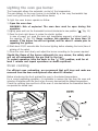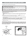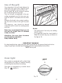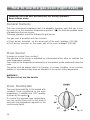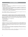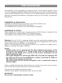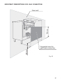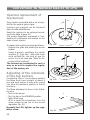
1
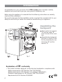
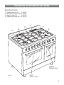
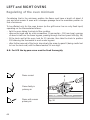
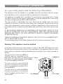
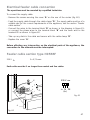
Twin cavity
gas cookers
RC 9320 ..
GB
Users Operating Instructions
Installation instructions
Before operating this cooker,
please read these instructions carefully
Dear Customer
Thank you for choosing one of our appliances, carefully designed and built by
our specialist staff and thoroughly tested to satisfy your cooking requirements.
We suggest that you read this Instruction Booklet so that you will understand
fully how to operate your appliance.
Please keep the booklet handy. You may wish to refer to it at a later date.
CDA
Important:
This appliance is designed and manufactured solely for the cooking of domestic
(household) food and is not suitable for any non domestic application and therefore should not be used in a commercial environment.
The appliance guarantee will be void if the appliance is used within a non domestic environment i.e. a semi commercial, commercial or communal environment.
2
Contents
Model RC 9320 ..
Page Number
Introduction . . . . . . . . . . . . . . . . . . . . . . . . . . . . . . . . . . . . . . . . . . . . . . 4
Assembling the backguard . . . . . . . . . . . . . . . . . . . . . . . . . . . . . . . . . . . . 4
Features and technical data . . . . . . . . . . . . . . . . . . . . . . . . . . . . . . . . . . . 5
Control panel . . . . . . . . . . . . . . . . . . . . . . . . . . . . . . . . . . . . . . . . . . . . . 6
Minute counter . . . . . . . . . . . . . . . . . . . . . . . . . . . . . . . . . . . . . . . . . . . . 6
How to use the hob burners . . . . . . . . . . . . . . . . . . . . . . . . . . . . . . . . . . 7
How to use the gas oven (left oven) . . . . . . . . . . . . . . . . . . . . . . . . . . . 10
How to use the gas grill (left oven) . . . . . . . . . . . . . . . . . . . . . . . . . . . . . 12
How to use the gas oven (right oven) . . . . . . . . . . . . . . . . . . . . . . . . . . . 14
How to use the gas grill (right oven) . . . . . . . . . . . . . . . . . . . . . . . . . . . . 16
Rotisserie (right oven) . . . . . . . . . . . . . . . . . . . . . . . . . . . . . . . . . . . . . . . 18
Oven cooking temperatures . . . . . . . . . . . . . . . . . . . . . . . . . . . . . . . . . . 19
Do’s and do not’s . . . . . . . . . . . . . . . . . . . . . . . . . . . . . . . . . . . . . . . . . . 20
Important notes . . . . . . . . . . . . . . . . . . . . . . . . . . . . . . . . . . . . . . . . . . . 21
Care and maintenance . . . . . . . . . . . . . . . . . . . . . . . . . . . . . . . . . . . . . . 22
For the installer
Location . . . . . . . . . . . . . . . . . . . . . . . . . . . . . . . . . . . . . . . . . . . . . . . . . 28
Fitting the adjustable feet . . . . . . . . . . . . . . . . . . . . . . . . . . . . . . . . . . . 30
Moving and levelling the cooker . . . . . . . . . . . . . . . . . . . . . . . . . . . . . . 31
Stability bracket . . . . . . . . . . . . . . . . . . . . . . . . . . . . . . . . . . . . . . . . . . . 32
Provision for ventilation . . . . . . . . . . . . . . . . . . . . . . . . . . . . . . . . . . . . . . 33
Gas installation . . . . . . . . . . . . . . . . . . . . . . . . . . . . . . . . . . . . . . . . . . . . 34
Gas connection . . . . . . . . . . . . . . . . . . . . . . . . . . . . . . . . . . . . . . . . . . . 35
Conversion to Natural Gas or to LPG . . . . . . . . . . . . . . . . . . . . . . . . . . . . 38
Lubrication of the gas taps . . . . . . . . . . . . . . . . . . . . . . . . . . . . . . . . . . . 45
Electrical installation . . . . . . . . . . . . . . . . . . . . . . . . . . . . . . . . . . . . . . . . 46
Appliance servicing . . . . . . . . . . . . . . . . . . . . . . . . . . . . . . . . . . . . . . . . . 48
Guarantee . . . . . . . . . . . . . . . . . . . . . . . . . . . . . . . . . . . . . . . . . . . . . . . 49
3
Introduction
Congratulations on your purchase of this CDA cooker which has been carefully
designed and produced to give you many years of satisfactory use.
Before using this appliance it is essential that the following instructions are carefully
read and fully understood.
We would emphasise that the installation section must be fully complied with for your
safety to ensure that you obtain the maximum benefits from your appliance.
B
Assembling the
backguard
A
■
Remove the two spacers
“A” and the screw “B”
from the rear of the cooktop.
■
Assemble the backguard
as shown in figure 1 and
fix it by screwing the central screw “B” and the
spacers “A”.
Fig. 1
Declaration of
CE
conformity
✓ This cooker has been designed, constructed and marketed in compliance with:
- Safety requirements of EU Directive "Gas" 90/396/EEC;
- Safety requirements of EU Directive "Low Voltage" 2006/95/EC;
- Protection requirements of EU Directive "EMC" 89/336/EEC;
- Requirements of EU Directive 93/68/EEC.
4
GB
Features and technical data
Gas burners
1.
2.
3.
4.
Auxiliary burner (A)
Semi-rapid burner (SR)
Rapid burner (R)
Triple-ring burner (TR)
1,00 kW
1,75kW
3,00 kW
3,50 kW
1
3
2
1
4
2
Right
Gas oven
Fig. 2
Left
Gas oven
5
Control panel
Fig. 3
1
2
3
4
5
6
7
8
9
10
11
CONTROL PANEL - Controls description
1. Left gas oven/gas grill control knob
2. Left oven light control knob
3. Minute counter
4. Right oven rotisserie / light control knob
5. Front left burner control knob
6. Rear left burner control knob
7. Front central burner control knob
8. Rear central burner control knob
9. Rear right burner control knob
10. Front right burner control knob
11. Right gas oven/gas grill control knob
Minute counter
Minute counter
The minute counter is a timed acoustic
warning device which can be set for a
maximum of 60 minutes.
The knob (Fig. 4) must be rotated
clockwise as far as the 60 minute
position and then set to the required
time by rotating it anticlockwise.
Fig. 4
6
How to use the hob burners
Hob burners
Each hob burner is controlled by a separate gas tap operated by a control
knob (fig. 5) which has 3 positions
marked on the control panel, these are:
– Symbol
: tap closed (burner off)
– Symbol
: High (maximum)
– Symbol
: Low (minimum)
Push in and turn the knob anti-clockwise to the selected position.
Fig. 5
To turn the burner off, fully rotate the knob clockwise to the off position:
.
The maximum setting of the control tap is for boiling, the minimum setting is for slow
cooking and simmering.
All working positions must be choosen between the maximum and minimum setting,
never between the maximum setting and the “OFF” position.
Electric ignition
The sparks generated by the electrodes close to the burners will ignite the choosen
burner. Whenever the lighting of the burners is difficult due to peculiar conditions of
the gas features or supply, it is advised to repeat the ignition with the knob on “minimum” position.
Lighting of the hob burners
To ignite the burner, the following instructions are to be followed:
1) Lightly press and turn the knob anti-clockwise, and position the knob indicator to the
symbol
printed on the control panel (fig. 5).
2) Press the knob to operate the electric ignition; or, in the case of a mains failure light
the burner with a match or lighted taper.
3) Adjust the burner according to the setting required.
7
Choice of burner
The burner must be chosen according to the diameter of the pans and energy
required.
Burners
Pan diameter
Auxiliary
Semi-rapid
Rapid
Triple-ring
Wok
12 ÷ 14 cm
16 ÷ 24 cm
24 ÷ 26 cm
26 ÷ 28 cm
max 36 cm
Fig. 6
do not use pans with concave or convex bases
Saucepans with handles that are excessively heavy in relation to the weight of the pan
are less safe as they are more likely to tip.
Pans which are positioned centrally on burners are more stable than those which are
offset.
It is far safer to position the pan handles in such a way that they cannot be accidentally
knocked.
When deep fat frying fill the pan only one third full of oil.
DO NOT cover the pan with a lid and DO NOT leave the pan unattended.
In the unfortunate event of a fire, leave the pan where it is and turn off all controls.
Place a damp cloth or correct fitting lid over the pan to smother the flames.
DO NOT use water on the fire.
Leave the pan to cool for at least 30 minutes.
8
Correct use of triple-ring burner
The flat-bottomed pans are to be placed directly onto the pan-support.
To use the WOK you need to place the proper stand in order to avoid any faulty
operation of the triple-ring burner (Fig. 7 - 8).
IMPORTANT:
The special grille for wok pans (fig. 8) MUST BE PLACED ONLY over the pan-rest for
the triple-ring burner.
CORRECT
WRONG
Fig. 7
Fig. 8
9
How to use the gas oven (left oven)
Attention: the oven door becomes very hot during operation.
Keep children away.
General features
The oven is furnished completely clean; it is advisable, however, upon first use, to turn
the oven on to the maximum temperature (position
) to eliminate possible traces
of grease from the oven burner.
The same operation should be followed for grill burner.
The gas oven is provided with two burners:
a) Oven burner, mounted on the lower part of the oven (wattage: 3,70 kW)
b) Grill burner, mounted on the upper part of the oven (wattage: 2,50 kW).
Oven burner
It carries out normal “oven cooking”.
The gas flow to the burner is regulated by a thermostat which allow to maintain the
oven temperature constant.
The control of the temperature is assured by a thermostatic probe positioned inside the
oven.
The probe must be always kept in its housing, in a clean condition, as an incorrect
position or encrustment may cause an alteration in the control of the temperature.
WARNING:
The door is hot, use the handle.
Oven thermostat
The oven thermostat (fig. 9) is marked with
numbers, these correspond to the oven temperature, in addition the “OFF” position is
shown by the symbol .
To choose the required oven temperature,
turn the control knob until its line mark is
level with the temperature required on the
control panel (facia).
Fig. 9
10
Lighting the oven gas burner
The thermostat allows the automatic control of the temperature.
The gas delivery to the oven burner is controlled by a two way thermostatic tap
(oven and grill burners) with flame-failure device.
To light the oven burner operate as follow:
1) Open the oven door
WARNING: Risk of explosion! The oven door must be open during this
operation.
2) Lightly press and turn the thermostat knob anti-clockwise to max position “ ” (fig. 11).
3) Press the knob right down to prime the electric ignition.
In case of power cut, press the knob and immediately approach a lighted match to
the opening “A” (fig. 10). Never continue this operation for more than 15
seconds. If the burner has still not ignited, wait for about 1 minute prior to
repeating the ignition.
4) Wait about 10/15 seconds after the burner lighting before releasing the knob (time of
priming of the valve).
5) Close the oven door slowly and adjust the burner according to the power required.
Should the flame of the burner estinguish for any reason, the safety valve
will cut off automatically the gas flow to the tap.
To re-start operation, take the knob to the “ ” OFF position, wait for at
least 1 minute and repeat operations as above explained.
Oven cooking
For efficient oven preheating, we recommend that grill trays and racks are
removed from the oven and replaced after about 15 minutes.
Before introducing the food, preheat the oven to the desired temperature.
For a correct preheating operation, it is advisable to remove the tray from the oven and
introduce it together with the food, when the oven has reached the desired temperature.
Check the cooking time and turn off the oven 5 minutes before the theoretical time to
recuperate the stored heat.
A
Fig. 10
Fig. 11
11
How to use the gas grill (left oven)
Lighting the grill gas burner
Do not grill with oven door closed.
Always fit the heat shield supplied with the cooker under the front panel
before commencing operations (Fig. 14).
WARNING. The heat shield and the oven door reaches a very high temperature whilst in use. Keep children away and allow to cool before removing.
The grill burner generates the infra-red rays for grilling.
To light the grill burner operate as follow:
1) Open the oven door.
WARNING: Risk of explosion! The oven door must be open during this opera-
tion.
2) Lightly press and turn the thermostat knob clockwise to the
position (fig. 12).
3) Press the knob right down to prime the electric ignition.
In case of power cut, press the knob and put a lighted match to the right and left side of
the burner (fig. 13).
Never continue this operation for more than 15 seconds. If the burner has still
not ignited, wait for about 1 minute prior to repeating the ignition.
4) Wait about 10/15 seconds after the burner lighting before releasing the knob (time of
priming of the valve).
5) Half-close the oven door slowly.
Should the flame of the burner estinguish for any reason, the safety valve will
cut off automatically the gas flow to the tap. To re-start operation, take the
knob to the “ ” OFF position, wait for at least 1 minute and repeat operations as above explained.
Fig. 12
11
12
Fig. 13
Use of the grill
Very important: the grill must always be
used with the oven door slightly open
and with shield "A” mounted (Fig. 14).
Mount shield “A” which serves to protect
the control panel from the heat.
Turn on the grill, as explained in the preceding paragraphs and let the oven preheat for about 5 minutes with the door
ajar.
Introduce the food to be cooked, positioning the rack as close to the grill as possible.
The dripping pan should be placed
under the rack to catch the cooking juices
and fats.
Note: It is recommended that you do
not grill for longer than 30 minutes
at any one time.
Attention: the oven door becomes
very hot during operation.
Keep children away.
NE
T
HO
ZO
A
Fig. 14
Notes:
– The grill burner has only one setting,
that is full-on
– It is important that the heat shield is
fitted the correct way up, as shown in
the figure 14.
IMPORTANT WARNING
For best results when using the grill, place the shelf on the second level and when
using the grill pan handle avoid contact with the heat shield which will be
HOT during use
Oven light
The cooker is equipped with a light that
illuminates the oven to enable visually
controlling the food that is cooking.
This light is controlled by a switch knob
(Fig. 15 position).
Fig. 15
13
How to use the gas oven (right oven)
Attention: the oven door becomes very hot during operation.
Keep children away.
General features
The oven is furnished completely clean; it is advisable, however, upon first use, to turn
the oven on to the maximum temperature (position
) to eliminate possible traces
of grease from the oven burner.
The same operation should be followed for grill burner.
The gas oven is provided with two burners:
a) Oven burner, mounted on the lower part of the oven (wattage: 2,20 kW)
b) Grill burner, mounted on the upper part of the oven (wattage: 2,00 kW).
Oven burner
It carries out normal “oven cooking”.
The gas flow to the burner is regulated by a thermostat which allow to maintain the
oven temperature constant.
The control of the temperature is assured by a thermostatic probe positioned inside the
oven.
The probe must be always kept in its housing, in a clean condition, as an incorrect
position or encrustment may cause an alteration in the control of the temperature.
WARNING:
The door is hot, use the handle.
Oven thermostat
The oven thermostat (fig. 16) is marked with
numbers, these correspond to the oven
temperature, in addition the “OFF” position
is shown by the symbol .
To choose the required oven temperature,
turn the control knob until its line mark is
level with the temperature required on the
control panel (facia).
Fig. 16
14
Lighting the oven gas burner
The thermostat allows the automatic control of the temperature.
The gas delivery to the oven burner is controlled by a two way thermostatic tap
(oven and grill burners) with flame-failure device.
To light the oven burner operate as follow:
1) Open the oven door
WARNING: Risk of explosion! The oven door must be open during this
operation.
2) Lightly press and turn the thermostat knob anti-clockwise to max position “ ” (fig. 18).
3) Press the knob right down to prime the electric ignition.
In case of power cut, press the knob and immediately approach a lighted match to
the opening “A” (fig. 17). Never continue this operation for more than 15
seconds. If the burner has still not ignited, wait for about 1 minute prior to
repeating the ignition.
4) Wait about 10/15 seconds after the burner lighting before releasing the knob (time of
priming of the valve).
5) Close the oven door slowly and adjust the burner according to the power required.
Should the flame of the burner estinguish for any reason, the safety valve
will cut off automatically the gas flow to the tap.
To re-start operation, take the knob to the “ ” OFF position, wait for at
least 1 minute and repeat operations as above explained.
Oven cooking
For efficient oven preheating, we recommend that grill trays and racks are
removed from the oven and replaced after about 15 minutes.
Before introducing the food, preheat the oven to the desired temperature.
For a correct preheating operation, it is advisable to remove the tray from the oven and
introduce it together with the food, when the oven has reached the desired temperature.
Check the cooking time and turn off the oven 5 minutes before the theoretical time to recuperate the stored heat.
A
Fig. 17
Fig. 18
15
How to use the gas grill (right oven)
Lighting the grill gas burner
Do not grill with oven door closed.
Always fit the heat shield supplied with the cooker under the front panel
before commencing operations (Fig. 21).
WARNING. The heat shield and the oven door reaches a very high temperature whilst in use. Keep children away and allow to cool before removing.
The grill burner generates the infra-red rays for grilling.
To light the grill burner operate as follow:
1) Open the oven door.
WARNING: Risk of explosion! The oven door must be open during this opera-
tion.
2) Lightly press and turn the thermostat knob clockwise to the
position (fig. 19).
3) Press the knob right down to prime the electric ignition.
In case of power cut, press the knob and put a lighted match to the right and left side of
the burner (fig. 20).
Never continue this operation for more than 15 seconds. If the burner has still
not ignited, wait for about 1 minute prior to repeating the ignition.
4) Wait about 10/15 seconds after the burner lighting before releasing the knob (time of
priming of the valve).
5) Half-close the oven door slowly.
Should the flame of the burner estinguish for any reason, the safety valve will
cut off automatically the gas flow to the tap. To re-start operation, take the
knob to the “ ” OFF position, wait for at least 1 minute and repeat operations as above explained.
Fig. 19
11
16
Fig. 20
Use of the grill
H
O
T
Z
O
N
E
Very important: the grill must always be
used with the oven door slightly open and
with shield "A” mounted (Fig. 21).
Mount shield “A” which serves to protect the
control panel from the heat.
Turn on the grill, as explained in the preceding paragraphs and let the oven preheat for
about 5 minutes with the door ajar.
Introduce the food to be cooked, positioning
the rack as close to the grill as possible.
The dripping pan should be placed under
the rack to catch the cooking juices and fats.
A
Fig. 21
Note: It is recommended that you do not grill for longer than 30 minutes at
any one time.
Attention: the oven door becomes very hot during operation.
Keep children away.
Notes:
– The grill burner has only one setting, that is full-on
– It is important that the heat shield is fitted the correct way up, as shown in the figure
21.
IMPORTANT WARNING
For best results when using the grill, place the shelf on the second level and when
using the grill pan handle avoid contact with the heat shield which will be HOT during
use
Oven light
The cooker is equipped with a light that
illuminates the oven to enable visually
controlling the food that is cooking.
This light is controlled by a switch knob
(Fig. 22 position).
Fig. 22
17
Rotisserie (right oven)
This is used for spit roasting under the
grill and comprises:
– an electric motor fitted to the rear of
the oven
– a stainless steel skewer provided with
slide-out heatless handgrip and two
sets of adjustable forks
– a skewer support to be fitted in the
middle runner.
The rotisserie motor is operated by a
switch knob (Fig. 23).
Fig. 23
Use of the rotisserie
Very important: the rotisserie must always be used with the oven door ajar and
with shield “A” mounted (Fig. 21).
– Insert the tray into the lowest rack holders of the oven and insert the rod support
into the intermediate rack holders.
– Put the meat to be cooked onto the rod, being careful to secure it in the center with
the special forks.
– Insert the rod into the motor opening and rest it onto the support of the spit collar;
then remove the grip by turning it to the left.
Attention: the oven door becomes very hot during operation.
Keep children away.
It is recommended that you do not grill for longer than 30 minutes at any
one time.
Fig. 24
18
Oven cooking temperatures
MARK
APPROX.
TEMP.
HEAT OF
OVEN
TYPE OF DISH TO COOK
130
130°C
Very cool
oven
Meringue cakes,
slow cooking items
•
140°C
Cool or
slow oven
Milk puddings, very rich fruit
cakes, i.e., Christmas
155
155°C
Cool or
slow oven
Stews, casseroles, braising,
rich fruit cakes, i.e., Dundee
•
165°C
Warm oven
Biscuits, rich plain cakes
i.e., Madeira. Low temp. roasting
180
180°C
Moderate
oven
Plain cakes, Victoria
sandwich, raised meat pies
•
190°C
Fairly hot
oven
Small cakes, savoury flans,
fish
205
205°C
Hot oven
Plain cakes and buns, swiss rolls,
fruit pies. High temp. roasting
•
215°C
Moderately
hot oven
Bread and bread rolls etc., scones,
flaky and rough puff pastry,
yorkshire pudding
230
•
230
240
Very hot
oven
Sausage rolls, mince pies, puff
pastry, pizza
Browning ready cooked dishes
19
Do’s and do not’s
Do’s and do not’s
• Do not grill with oven door closed. Always fit the heat shield supplied with the cooker under the front panel before commencing operations.
• Do read the user instructions carefully before using the cooker for first time.
• Do allow the oven to heat for one and a half hours, before using for the first time, in
order to expel any smell from the new oven insulation, without the introduction of
food.
• Do clean your oven regularly.
• Do remove spills as soon as they occur.
• Do always use oven gloves when removing food shelves and trays from the oven.
• Do not allow children near the cooker when in use.
• Do not allow fat or oils to build up in the oven trays, or oven base.
• Do not place cooking utensils or plates directly onto the oven base.
• Do not grill food containing fat without using the grid.
• Do not cover the grilling grid with aluminium-foil.
• Do not use the oven tray for roasting.
• Do not place hot enamel parts in water. Leave them to cool first.
• Do not allow vinegar, coffee, milk, saltwater, lemon or tomato juice to remain in contact with enamel parts (inside the oven and on the oven tray).
• Do not use abrasive cleaners or powders that will scratch the surface of the stainless
steel and the enamel.
• Do not attempt to repair the internal workings of your cooker.
• Do remove the protective film before the first use.
• Fire risk! Do not store flammable material in the oven and in the storage compartment.
20
For your safety
The product should only be used for its intended purpose which is for the cooking of
domestic foodstuffs.
Under no circumstances should any external covers be removed for servicing or maintenance except by suitably qualified personnel.
Attention
The appliance gets very hot, mainly around the cooking areas. It is very important that children are not left alone in the kitchen when you are cooking.
Oven door guard
The glass on the oven door reaches high temperatures during operation.
For child safety, a door guard can be fitted to prevent contact with the hot glass.
The door guard is supplied as an accessory at extra cost, if required.
Contact the After-Sales Service and indicate the model name of your product (see product data plate - Mod. RC 9320 ..).
Important notes
Installation, and any demonstration, information or adjustments are not included in
the warranty.
The cooker must be installed by a qualified person in accordance with the relevant
Standards.
In the UK C.O.R.G.I registered installers are authorised to undertake the installation and
service work in compliance with the applicable regulations.
21
Care and maintenance
Important:
As a safety measure, before you start cleaning the cooker be sure to disconnect it from
the mains supply.
Do not use a steam cleaner because the moisture can get into the appliance
thus make it unsafe.
The use of suitable protective clothing/gloves is recommended when handling or cleaning of this appliance.
WARNING
When correctly installed, your product meets all safety requirements laid down for this
type of product category.
However special care should be taken around the rear or the underneath of the appliance as these areas are not designed or intended to be touched and may contain
sharp or rough edges, that may cause injury.
Flexible tube
From time to time, check the flexible tube connecting the gas supply to the cooker.
It must be always in perfect condition; in case of damage arrange for it to be replaced
by a C.O.R.G.I. registered installer.
Gas taps
If a tap becomes stiff, do not force; contact your local Service Centre.
Cleaning the hob
Spillage on the hob can usually be removed by a damp soapy cloth. More obstinate
stains can be removed by rubbing gently with a soapy nylon (non metal) scouring pad
or mild household cleaner.
22
Enamelled parts
All the enamelled parts must be cleaned with a sponge and soapy water only or other
non-abrasive products.
Dry preferably with a microfibre or soft cloth.
Stainless steel, aluminium, painted parts and silkscreen printed surfaces
Clean using an appropriate product. Always dry thoroughly.
Stainless steel surfaces: can be cleaned with an appropriate stainless steel cleaner.
IMPORTANT: these parts must be cleaned very carefully to avoid scratching and abrasion. You are advised to use a soft cloth and neutral soap.
CAUTION: Do not use abrasive substances or non-neutral detergents as these will
irreparably damage the surface.
Changing the oven light
1. Disconnect the electrical power supply (for example, by switching off the main
power switch).
2. Unscrew the light cover
3. Fit a new bulb.
4. Refit the cover.
Note:
Use only bulbs designed to resist up to 300°C with the following characteristics: 230 V,
type E14 and same power (check watt power as stamped in the bulb itself) of the
replaced bulb.
23
Burners
They can be removed and washed only with
soapy water.
Detergents can be used but must not be
abrasive or corrosive.
Do not use abrasive sponges or pads.
Do not put in dishwasher.
After each cleaning, make sure that the
burner-caps, as well as the burners, have
been well wiped off and CORRECTLY
POSITIONED.
It is essential to check that the burner
flame distributor F and the cap C has been
correctly positioned (see fig. 25) - failure to
do so can cause serious problems.
Check that the electrode “S” (fig. 25) is
always clean to ensure trouble-free
sparking.
C
F
S
Fig. 25
Note:
The electrode “S” must be very carefully cleaned.
To avoid damage to the electric ignition do not use it when the burners are not
in place.
Triple ring burner
The triple ring burner must be correctly positioned (see figs. 26-27); the burner rib
must be located correctly in the burner base as shown by the arrow.
The burner correctly positioned must not rotate (fig. 27).
Then position the cap A and the ring B (fig. 27).
A
Fig. 26
24
Fig. 27
B
Removal of the inner glass door panel
– The inner glass door panel can easily be removed for cleaning by unscrewing
the fixing screws (fig. 28).
– When re-assembly ensure that the inner glass is correctly positioned and do not
over tighten the screws.
Do not use harsh abrasive cleaners or sharp metal scrapers to clean the oven
door glass since they can scratch the surface, which may result in shattering
of the glass.
Fig. 28
Storage compartment
– The storage compartment is accessible through the pivoting panel.
Attention: Do not store flammable material in the oven, or the storage
compartment.
Fig. 29
25
Inside of oven
The oven should always be cleaned after
use when it has cooled down.
The cavity should be cleaned using a
mild detergent solution and warm
water. Suitable proprietary chemical
cleaners may be used after first consulting with the manufacturers recommendations and testing a small sample of the
oven cavity. Abrasive cleaning agents or
scouring pads/cloths should not be used
on the cavity surface.
Fig. 30
NOTE: The manufacturers of this appliance will accept no responsibility for
damage caused by chemical or abrasive
cleaning.
Let the oven cool down and pay special attention no to touch the hot
heating elements inside the oven cavity.
Assembling and removing the side racks
– Fit the side runner frames into the
holes on the side walls inside the oven
(Fig. 30).
– Slide the tray and rack into the runners
(Fig. 31).
The rack must be fitted so that the safety catch, which stops it sliding out,
faces the inside of the oven.
– To dismantle, operate in reverse order.
26
Fig. 31
Removing the oven
door
Fig. 32a
Please operate as follows:
• Open the door completely.
• The swivel retainers of the rh and lh
hinges (fig. 32a) are hooked onto
the metal bar above them (fig. 32b).
• Lift the oven door slightly. The noch
on the bottom of the hinge will disengage (fig. 32c).
• Now pull the oven door forwards off
the appliance. Release both hinge
sections from the slots (fig. 32d).
Fig. 32b
Door assembly
• Grip the door (as indicated in figure
32) and refit it in reverse order of
removing procedure.
Fig. 32c
Fig. 32d
Fig. 32
27
FOR THE INSTALLER
Location
This cooker has class “2/1” overheating protection so that it can be installed
next to a cabinet.
The appliance may be installed in a kitchen, Kitchen/diner or a bed sitting room, but
not in a room or space containing a bath or a shower.
The appliance must not be installed in a bed-sitting room of less than 20 m3.
The appliance is designed and approved for domestic use only and should not be
installed in a commercial, semi commercial or communal environment.
Your product will not be guaranteed if installed in any of the above environments and
could affect any third party or public liability insurances you may have.
If the cooker is installed adjacent to furniture which is higher than the gas hob cooktop,
a gap of at least 200 mm must be left between the side of the cooker and the furniture.
The furniture walls adjacent to the cooker must be made of material resistant to heat.
The veneered synthetic material and the glue used must be resistant to a temperature
of 90°C in order to avoid ungluing or deformations.
Curtains must not be fitted immediatly behind appliance or within 500 mm of the sides.
It is essential that the cooker is positioned as stated in Fig. 33.
28
The cooker must be installed by a qualified technician and in compliance
with local safety standards.
450 mm
650 mm
If the cooker is located on a pedestal it is necessary to provide safety measures to prevent falling out.
200 mm
500 mm
ent
air v
Fig. 33
29
Fitting the adjustable feet
The adjustable feet must be fitted
to the base of the cooker before
use.
Rest the rear of the cooker an a
piece of the polystyrene packaging
exposing the base for the fitting of
the feet.
Fig. 34
Fig. 35
30
Fit the 4 legs by screwing them
tight into the support base as
shown in picture 35.
Moving the cooker
Warning
When raising cooker to upright
position always ensure two people
carry out this manoeuvre to prevent damage to the adjustable feet
(fig. 36).
Warning
Be carefull: do not lift the cooker
by the door handle when raising
to the upright position (fig. 37).
Fig. 36
Warning
When moving cooker to its final position DO NOT DRAG (fig. 38).
Lift feet clear of floor (fig. 36).
Fig. 32
Levelling the cooker
The cooker may be levelled by screwing the lower ends of the feet IN or
OUT (fig. 39).
Fig. 37
Fig. 38
Fig. 39
31
Stability bracket
We recommend a stability bracket is fitted to the cooker.
The type shown in fig. 40 can be purchased from most plumbers merchants and do it
yourself (D.I.Y.) shops.
Existing slot in
rear of cooker
Brackets
Fig. 40
Dotted line showing the
position of cooker when fixed
3
Outline of cooker
backplate at the
engagement slot
Wall fixing
Floor fixing
Dimension is in millimetres
32
Provision for ventilation
✓ The appliance should be installed into a room or space with an air supply in accor-
dance with BS 5440-2: 2000.
✓ For rooms with a volume of less than 5 m3 - permanent ventilation of 100 cm2 free
area will be required.
✓ For rooms with a volume of between 5 m3 and 10 m3 a permanent ventilation of
50 cm2 free area will be required unless the room has a door which opens directly to
the outside air in which case no permanent ventilation is required.
✓ For rooms with a volume greater than 10 m3 - no permanent ventilation is required.
NB. Regardless of room size, all rooms containing the appliance must have
direct access to the outside air via an openable window or equivalent.
✓ Where there are other fuel burning appliances in the same room, BS 5440-2: 2000
should be consulted to determine the correct amount of free area ventilation requirements.
✓ The above requirements allow also for use of a gas oven and grill but if there are
other gas burning appliances in the same room, consult a qualified engineer.
33
Gas installation
IMPORTANT NOTE
This appliance is supplied for use on NATURAL GAS or LPG (check the gas regulation
label attached on the appliance).
✓ Appliances supplied for use on NATURAL GAS: they are adjusted for this gas only and
cannot be used on any other gas (LPG) without modification. The appliances are
manufactured for conversion to LPG.
✓ Appliances supplied for use on LPG: they are adjusted for this gas only and cannot
be used on any other gas (NATURAL GAS) without modification. The appliances are
manufactured for conversion to NATURAL GAS.
If the NATURAL GAS/LPG conversion kit is not supplied with the appliance this kit can
be purchased by contacting the After-Sales Service.
INSTALLATION & SERVICE REGULATIONS (UNITED KINGDOM)
It is a legal requirement that all gas appliances are Installed & Serviced by a competent
person in accordance with the current editions of the following Standards &
Regulations or those regulations appropriate to the geographical region in which they
are to be installed:
✓ Gas Safety (Installation & Use) Regulations
✓ Building Regulations
✓ British Standards
✓ Regulations for Electrical Installation
Installation and service of any gas product must be made by a suitably qualified person
competent on the type of product being installed or serviced and holding a valid
certificate of competence for the work being carried out. Currently the proof of
competence is the Accredited Certification Scheme (ACS) or S/NVQ that has been
aligned to the ACS.
It is also a requirement that all businesses or self employed installers are members of a
class of person approved by the Health and Safety Executive. Currently the only body
with such approval is CORGI.
Failure to install the appliance correctly could invalidate any manufacturers warranty
and lead to prosecution under the above quoted regulation.
34
Gas connection
The installation of the gas appliance to Natural Gas or LP Gas must be carried out by a
C.O.R.G.I. registered installer. Installers shall take due account of the provisions of the
relevant British Standards Code of Practice, the Gas Safety Regulations and the Building
Standards (Scotland)(Consolidation) Regulations issued by the Scottish Development
Department.
Installation to Natural Gas
Installation to Natural Gas must conform to the Code of Practice, etc.
The supply pressure for Natural Gas is 20 mbar.
The installation must conform to the relevant British Standards.
Installation to LP Gas
When operating on Butane gas a supply pressure of 28-30 mbar is required. When
using Propane gas a supply pressure of 37 mbar is required.
The installation must conform to the relevant British Standards.
Warning: Only a C.O.R.G.I. registered installer, also with technical knowledge of electricity should install the appliance. He should observe the Regulations and Codes of
Practice governing such installation of gas appliances.
Note: It is recommended that the gas connection to the appliance is installed with a
flexible connecting tube made to BS5386.
Notes:
✓ Flexible hoses can be used where the sited ambient temperature of the
hose does not exceed 70°C. These hoses must be manufactured in
accordance with BS669 part 1 and be of the correct construction for the
type of gas being used.
✓ Gas hoses designed for natural gas MUST NOT be used for supplying LPG
gas (LPG gas hoses can be identified by a either a red band or stripe on
the rubber outer coating of the hose).
The hose should not be crushed or trapped or be in contact with sharp or
abrasive edges.
Using a suitable leak detection fluid solution (e.g. Rocol) check each gas connection
one at a time by brushing the solution over the connection.
The presence of bubbles will indicate a leak.
If there is a leak, tighten the fitting and then recheck for leaks.
IMPORTANT!
Do not use a naked flame to test for leaks.
35
Gas connection
GB
Cat: II 2H3+
The gas supply must use the nearest gas inlet pipe which is located at the left or the
right hand side at the rear of the appliance (figs. 41, 43).
The hose should also be connected in such away that it does not touch the floor.
To screw the connecting tube operate with two spanners (fig. 42).
The unused end inlet pipe must be closed with the plug interposing the gasket.
After connecting to the mains, check that the coupling are correctly sealed,
using soapy solution, but never a flame.
Fig. 42
Left gas
inlet pipe
Right gas
inlet pipe
Plug
1/2” BSP (male)
Fig. 41
36
IMPORTANT PRESCRIPTIONS FOR GAS CONNECTION
700 mm
Rear wall
200 mm
Suggested area for
gas mains connection
Fig. 43
37
Conversion to Natural Gas or to LPG
Injectors replacement of
top burners
J
Every cooker is provided with a set of injectors for the various types of gas.
Injectors not supplied can be obtained
from the After-Sales Service.
Select the injectors to be replaced according to the table at page 39.
The nozzle diameters, expressed in hundredths of a millimetre, are marked on the
body of each injector.
To replace the injectors proceed as follows:
– Remove the grids and extract the burner
bodies.
– Using a wrench, substitute the nozzle
injectors “J” (Figs. 44a - 44b) with those
most suitable for the kind of gas for
which it is to be used (see “Table for the
choice of the injectors”).
The burners are constructed in such a
way so as not to require the regulation of the primary air.
Fig. 44a
J
Adjusting of the minimum
of the top burners
Considering that in the minimum position
the flame must have a length of about 4
mm and must remain lit even with a quick
turn from the maximum position to that of
minimum.
The flame adjustment is done in the following way:
– Turn on the burner
– Turn the tap to the MINIMUM position
– Take off the knob
– With a small flat screwdriver turn the
screw inside the tap rod to the correct
regulation (fig. 45).
Normally for LPG, tighten up the regulation screw.
38
Fig. 44b
Fig. 45
Table for the choice of the injectors
GB
BURNERS
Cat:
Nominal
Power
Reduced
Power
[kW]
[kW]
G 20
20 mbar
G 30 - 28-30 mbar
G 31 - 37 mbar
By-pass
[1/100 mm]
ring
Ø injector Tube
opening
[1/100 mm]
II 2H3+
[mm]
By-pass Ø injector
[1/100 mm] [1/100 mm]
Tube ring
opening
[mm]
1,00
0,30
27
50
-
72 (X)
-
Semi-rapid (SR)
1,75
0,45
32
65
-
97 (Z)
-
adjustable
Auxiliary (A)
Rapid (R)
3,00
0,75
42
85
-
Triple-ring
3,50
1,50
65
95
-
Oven (left)
3,70
0,75
40
92
fully open
Grill (left)
2,50
-
-
80
fully open
Oven (right)
2,20
0,63
38
72
fully open adjustable
Grill (right)
2,00
-
-
70
fully open
-
-
115 (Y)
-
135 (T)
-
140
5
120
4
110
4
105
2
INCREASE OF AIR NECESSARY FOR GAS COMBUSTION (2 m3/h x kW)
BURNERS
Air necessary for combustion [m3/h]
Auxiliary (A)
2,00
Semi-rapid (SR)
3,50
Rapid (R)
6,00
Triple-ring
7,00
Oven (left)
7,40
Grill (left)
5,00
Oven (right)
4,40
Grill (right)
4,00
39
LEFT OVEN
Oven burner and grill
burner replacement of
injectors
a) oven burner
Fig. 46
– Lift and remove the lower panel
inside the oven.
– Remove the burner securing screw
(fig. 46).
– Withdraw the burner as shown in figure 47 and rest it inside the oven.
Take care not to damage the wire to
the ignition electrode and the safety
valve probe.
– Using a 7 mm box spanner, unscrew
the injector (indicated by the arrow
in fig. 47) and replace it by the proper one according to the kind of gas.
Then replace the burner repeating
the above steps in reverse order.
Fig. 47
b) grill burner
– Remove the burner by unscrewing
the front screw (fig. 48).
Gently suspend the burner as shown
in figure 49. Be careful not to
damage the wire of the electric
ignition and the probe of the safety
valve.
Fig. 48
– Using a 7 mm box spanner, replace
the injector (indicated by the arrow
in fig. 49) by the proper one
according to the kind of gas.
– Replace the burner repeating the
above steps in reverse order.
Fig. 49
40
Regulation of air supply to oven and grill burners
Using a cross-head screwdriver, slacken the screw securing the air flow regulation
collar (fig. 50 and 51) and move the collar forward or backward to increase or reduce
the air aperture in accordance with gas type and the indications in the “TABLE FOR
THE CHOICE OF THE INJECTORS”.
Light the burner and check the flame.
Fig. 51
Ring opening
Fig. 50
Ring opening
41
RIGHT OVEN
Oven burner and grill
burner replacement of
injectors
a) oven burner
Fig. 52
– Lift and remove the lower panel
inside the oven.
– Remove the 2 burner securing screws
(fig. 52).
– Withdraw the burner as shown in figure 53 and rest it inside the oven.
Take care not to damage the wire to
the ignition electrode and the safety
valve probe.
– Using a 7 mm box spanner, unscrew
the injector (indicated by the arrow
in fig. 53) and replace it by the proper one according to the kind of gas.
Then replace the burner repeating
the above steps in reverse order.
Fig. 53
b) grill burner
– Remove the burner by unscrewing
the front screw (fig. 54).
Gently suspend the burner as shown
in figure 55. Be careful not to
damage the wire of the electric
ignition and the probe of the safety
valve.
Fig. 54
– Using a 7 mm box spanner, replace
the injector (indicated by the arrow
in fig. 55) by the proper one
according to the kind of gas.
– Replace the burner repeating the
above steps in reverse order.
Fig. 55
42
Regulation of air supply to oven and grill burners
Using a screwdriver, slacken the screw securing the air flow regulation collar (fig. 56
and 57) and rotate the collar clockwise or anti-clockwise to increase or reduce the
air aperture in accordance with gas type and the indications in the “TABLE FOR
THE CHOICE OF THE INJECTORS”.
Light the burner and check the flame.
Fig. 57
Ring opening
Fig. 56
43
LEFT and RIGHT OVENS
Regulating of the oven minimum
Considering that in the minimum position the flame must have a length of about 4
mm and must remain lit even with a brusque passage from the maximum position to
that of minimum.
To be effected only for the oven burner (as the grill burner has an only fixed input)
operating on the thermostat as follows:
– light the oven taking the knob to Max. position.
– remove the knob and by a thin screwdriver (3 mm section - 100 mm long) unscrew
of about a half turn the screw by-pass, passing through the front panel hole (fig. 58)
– fit the knob and let the oven heat for 10 minutes, then take the knob to position
130 allowing the thermostat to work under by-pass.
– after further removal of the knob, stop slowly the screw by-pass G (being careful not
to turn the knob rod) until the flame reaches 3-4 mm high.
N.B. For LPG the by-pass screw must be fixed thoroughly.
Flame correct
G
Flame faulty in
primary air
Flame with excess
primary air
44
Fig. 58
Lubrication of the gas taps
The operations must be executed by a qualified technician.
IMPORTANT
All intervention regarding installation maintenance and conversion of the
appliance must be fulfilled with original factory parts.
The manufacturer declines any liability resulting from the non-compliance of
this obligation.
45
Electrical installation
For your safety please read the following information:
This appliance must be installed by a qualified technician according with the current
local regulations and in compliance with the manufacturer instructions.
This appliance is supplied with a moulded 13 amp three pin mains plug with a 3 amp
fuse fitted. Should the fuse require replacement, it must be replaced with a fuse rated
at 3 amp and approved by ASTA or BSI to BS 1362.
The plug contains a removable fuse cover that must be refitted when the fuse is
replaced. In the event of the fuse cover being lost or damaged, the plug must not be
used until a replacement cover has been obtained. Replacement fuse covers can be
purchased from your nearest electrical dealer and must be the sarne colour as the original.
IF THE MOULDED MAINS PLUG IS UNSUITABLE FOR THE SOCKET OUTLET IN YOUR
HOME OR IS REMOVED FOR ANY OTHER REASON, THEN THE FUSE SHOULD BE
REMOVED AND THE CUT OFF PLUG DISPOSED OF SAFELY TO PREVENT THE HAZARD
OF ELECTRIC SHOCK.
THERE IS A DANGER OF ELECTRICAL SHOCK IF THE CUT OFF PLUG IS INSERTED INTO
ANY 13 AMP SOCKET OUTLET.
If a replacement plug is to be fitted, please observe the wiring code shown below.
Warning! This appliance must be earthed
A properly earthed three pin plug (fused at 3 amps, to BS 1362 ASTA approved) must
be used. As the colours of the wires in the mains lead of this appliance may not correspond with the coloured markings identifying the terminals in your plug, proceed as
follows.
The wire which is coloured GREEN &
YELLOW must be connected to the
terminal in the plug which is marked Green & Yellow
with letter "E" or by the Earth symbol Earth
or coloured GREEN & YELLOW.
3 amp fuse
The wire which is coloured BLUE
must be connected to the terminal
which is marked with the letter "N" or
coloured BLACK.
The wire which is coloured BROWN
must be connected to the terminal
which is marked with the letter "L" or
coloured RED.
Blue Neutral
Brown Live
Fig. 59
46
Electrical feeder cable connection
The operations must be executed by a qualified technician.
To connect the supply cable:
- Remove the screws securing the cover “A” on the rear of the cooker (fig. 60).
- Feed the supply cable through the cable clamp “D”. The supply cable must be of a
suitable size for the current requirements of the appliance; see the section “Feeder
cable section”.
- Connect the wires to the terminal block “B” as shown in the diagram in figure 61;
or connect the phase wires to the terminal block “B” and the earth wire to the
terminal PE as shown in figure 60.
- Take up any slack in the cable and secure with the cable clamp “D”.
- Replace the cover “A”.
Before effecting any intervention on the electrical parts of the appliance, the
connection to the network must be interrupted.
Feeder cable section type H05RRF
3 x 0,75 mm2
230 V
Earth cable must be 2 cm longer than neutral and live cables.
230 V
PE
N
L
B
D
L1 N PE
(L2)
Fig. 61
A
Fig. 60
47
Appliance servicing
CDA provide a quality and effective after-sales service to cover all your
servicing needs.
Please attach your receipt to this page for safekeeping.
Please help us to help you by having the following information available
when booking a service-call:
1. Model type, make and model – see the product data plate.
2. Evidence of installation / purchase date
3. Retailer where appliance was purchased
4. Clear and concise details of the fault
5. Full address including postcode and any contact phone numbers
Contact telephone numbers
CDA Customer Care Department
• Telephone: 01949 862012
• Fax: 01949 862003
• Email: [email protected]
48
Guarantee
CDA appliances carry a five-year parts and a one-year labour guarantee.
CDA will repair or replace any defect or part attributable to faulty material or workmanship. Within the first year this will be free of both labour and parts charges. After the
first year and within five years, the parts will be supplied free of charge provided that
the repair is carried out by an agent authorised by CDA and the labour will be charged
at the commercial rate applicable at the time of repair.
The appliance must have been installed by a suitably qualified person and in accordance with the manufacturer’s instructions and current legislation. The guarantee does
not cover faults caused by the incorrect fitting of appliances.
Limit of Cover
• The guarantee does not cover cosmetic damage e.g. discolouration or oxidisation.
• Proof of purchase or installation date must be produced before a service-call will be
booked.
• The appliance must be used for domestic purposes only. Appliances used for commercial or professional purposes are not covered by the guarantee. Commercial warranty is available at extra cost.
• The appliance must not be modified or tampered with or repair attempted by any
unauthorised person.
• The guarantee does not cover damage caused in transit or by misuse, accident,
abuse or neglect.
• The guarantee does not cover routine maintenance.
• Use of parts not supplied or recommended by |C|D|A| will invalidate the warranty.
• Rubber seals, filters, removable glass parts, control knobs and buttons, fuses and
light bulbs will need replacing periodically and are not covered by the guarantee.
• Second-hand or reconditioned appliances are not covered by the guarantee.
The conditions under which this guarantee is offered are in addition to the statutory
rights of the domestic purchaser and these statutory rights are not affected by this
guarantee.
CDA reserve the right to change specification without prior notice.
49
50
51
Descriptions and illustrations in this booklet are given as simply indicative.
The manufacturer reserves the right, considering the characteristics of the models described here, at
any time and without notice, to make eventual necessary modifications for their construction or for
commercial needs.
Cod. 1103123
ß2
RC 9320 .. cookers
The
Group Ltd
Harby Road Langar Nottingham NG13 9HY UK
VAT No : 528 7168 19 Registered in England : 2621460
●
●
●
●
●