1
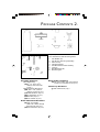
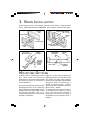
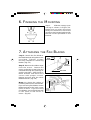
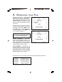
Please Read and Save Instructions
Modelo No. F547
Instruction Manual
Manual de Instrucciones
Model No. F547
Favor - Lea Y Guarde Instrucciones
Congratulations on your purchase of a
Minka-Aire™ ceiling fan! Your new fan will be
a beautiful addition to your home, and will keep
you comfortable throughout the year.
Minka-Aire™ offers a variety of ceiling fans: combinations of wood and brass
finishes, solid designer colors, and unique glass and crystal designs. A large
selection of light fixtures and light kits are also available. Ask your dealer about
accessories that will allow you to customize your fan.
We're certain that your Minka-Aire™ fan will
provide you with many years of comfort, energy savings and satisfaction.
To ensure your personal safety and to maximize the performance of your fan,
please read this manual thoroughly.
LIMITED LIFETIME WARRANTY
Minka-Aire™ warrants this fan to be free from defects in
material and workmanship for one year from the date of
purchase, except for the motor. Minka-Aire™ warrants to the
original owner that the motor in this fan shall be free from
defects in material and workmanship as long as the original
purchaser owns the fan. Minka-Aire's™ only obligation under
this limited warranty is to replace, repair or refund the purchase
price any fan confirmed by Minka-Aire™ to be defective in
material or workmanship after such fan is returned to
Minka-Aire™ by the original purchaser along with a proof of
purchase and with shipping charges prepaid. This warranty
shall not apply to fans which have been damaged as a result of
improper installation, removed from the original installation or
subjected to use for which the fan was not designed. The
customer shall be responsible for any cost of removing the old
fan, installing a new fan or any other costs. This limited lifetime
warranty is in lieu of all other expressed warranties.
Minka-Aire™ shall under no circumstances be liable for any
incidental or consequential damages.
Date Purchased
Store Purchased
Model No.
Serial No.
F547
CONTENTS
SAFETY FIRST ............................................................ 1
PACKAGE CONTENTS ................................................... 2
BEGIN INSTALLATION ................................................... 3
HANGING
THE
FAN ...................................................... 4
THE ELECTRICAL CONNECTIONS ..................................... 5
FINISHING THE MOUNTING ............................................ 7
ATTACHING THE FAN BLADES ........................................ 7
ATTACHING THE SWITCH CUP............................ ............ 8
OPERATING YOUR FAN ................................................ 9
MAINTENANCE ......................................................... 10
TROUBLESHOOTING ................................................... 11
SPECIFICATIONS ........................................................ 11
1151 W. Bradford Ct., Corona, CA 92882
All Rights Reserved
LISTED
E75795
1. SAFETY FIRST
1. Before you begin installing the fan,
disconnect the power by removing
fuses or turning off circuit breakers.
2. Be Cautious! Read all instructions
and safety information before
installing your new fan. Review the
accompanying assembly diagrams.
3. Make sure that all electrical
connections comply with local codes,
ordinances, or National Electrical
Codes. Hire a qualified electrician or
consult a do-it-yourself wiring
handbook if you are unfamiliar with
installing electrical wiring.
4. Make sure the installation site you
choose allows the fan blades to
rotate without any obstructions.
Allow a minimum clearance of 7
feet from the floor to the lowest edge
of the blades. Fan blades must have a
minimum clearance of 18" from
the wall.
5. If you are mounting the fan to a
ceiling outlet box, use a metal
octagonal outlet box. Secure the box
directly to the building structure. The
outlet box and its support must be
able to support the moving weight of
the fan (at least 50 lbs.). Do not use
a plastic outlet box.
6. Attach the hanger bracket using the
hardware supplied with the fan.
7. If you are mounting the fan to a
joist, make sure it is able to support
the moving weight of the fan (at least
50 lbs.).
8. After you install the fan, make sure
that all connections are secure to
prevent the fan from falling.
9. Do not insert anything into the fan
blades while fan is operating.
10. Turn the fan off and wait for it to
stop before reversing fan direction.
NOTE: The important safeguards and
instructions appearing in this manual
are not meant to cover all possible
conditions and situations that may
occur. It must be understood that
common sense, caution and care are
factors which can not be built into this
product. These factors must be supplied
by the person(s) installing, caring for
and operating the unit.
PACKAGE CONTENTS 2.
4
2
7
5
3
6
8
1
A
C
Unpack your fan and check the contents.
You should have the following items:
F
1.
2.
3.
4.
5.
6.
7.
8.
B
D
H
G
E
J
Fan Blades (5)
Fan Motor/Housing Assembly
Switch Cup
Hanger Bracket
Standard Downrod Assembly
Canopy
Blade Bracket (5)
Balancing Kit
K
Mounting Hardware:
J-Box Mounting:
(A)10# x 1- 1⁄2"L (10# x
38mm) wood screws
(2 pcs.)
Hanger Bracket Mounting:
(B)8-32x 1- 1⁄2" (8-32 x
36mm) screws (2 pcs.)
(C)Metal Washers (2 pcs.)
(D)Lockwashers (2 pcs.)
(E)Wire Nut (3 pcs.)
(K)Star washer (2 pcs.)
Blade Attachment Hardware:
(F)3⁄16"-24 x 5⁄16"L
(3⁄16"-24 x 8mm) flange
head screws (15 pcs.)
(G)Fiber Washers (15 pcs.)
Blade Holder Hardware:
(H)1⁄4"-20 x 7⁄16"L (1⁄4"-20 x 11mm)
screws w/lockwashers (10 pcs.)
Switch Cup Hardware:
(J) Pull Chain Fob (1 pc.)
3. BEGIN INSTALLATION
Tools Required: You will need a phillips screw driver, slotted screw
driver, adjustable wrench, stepladder, wire cutters, and electrical tape.
CEILING
JOIST
PARALLEL WOOD BRACE
(Min. 2" Thick)
CROSS BRACE
OUTLET
BOX
OUTLET BOX
CEILING JOIST OR
CROSS BRACE
CEILING
JOIST
FIG. 1
FIG. 2
Angled Ceiling
Maximum 29° angle
PROVIDE
STRONG
SUPPORT
HANGER BAR
(OPTIONAL)
HANGER
OPENING
MUST BE
FACING
UPSIDE
OUTLET BOX
RECESSED
OUTLET
BOX
FIG. 3
CEILING
JOIST
HANGER
BRACKET
FIG. 4
MOUNTING OPTIONS
If there isn't an existing mounting
box, then read the following
instructions. Disconnect the power
by removing fuses or turning off
circuit breakers.
Secure the outlet box directly to the
building structure. The outlet box
and its support must be able to fully
support the moving weight of the
fan (at least 50 lbs.). Use a U.L.
Listed metal outlet box. Do not use
a plastic outlet box.
Figures 1, 2 and 3 are examples of
different ways to mount the outlet
box. Note: You may need a longer
downrod to maintain proper blade
clearance when installing on a
steep, sloped ceiling. Longer
downrods are available from your
Minka-Aire™ dealer.
To hang your fan where there is
an existing fixture but no ceiling
joist, you may need to install a
hanger bar as shown in Figure 4
(available at your Minka-Aire™
dealer).
HANGING THE FAN 4.
REMEMBER to turn off the power.
Follow the steps below to hang
your fan properly:
Step 1. Secure the hanger bracket
to the ceiling outlet box using
screws, lock washers, and flat
washers included with the fan.
(Fig. 5)
OUTLET BOX
SET
SCREWS
HANGER BRACKET
FIG. 5
FIG. 6
Step 2. Loosen the two set screws
in the top coupling of the motor
assembly. (Fig. 6)
Step 3. Remove downrod hanger
ball by loosening set screw,
removing the cross pin, and
sliding ball off rod. Remove the
hitch pin and lock pin. (Fig. 7)
Step 4. Carefully feed fan wires up
through the downrod. (Fig. 8)
Thread the rod into the coupling,
next line up holes, then replace
lock pin and hitch pin. Tighten set
screws.
Step 5. Slip canopy onto downrod.
(Fig. 9). Carefully reinstall hanger
ball onto rod being sure that
crosspin is in correct position, set
screw is tight and wires are not
twisted.
Step 6. Now lift motor assembly
into position and place downrod
ball into hanger bracket. Rotate
until the check groove has dropped
into the registration slot and seats
firmly. (Fig. 10). Rod should not
rotate if this is done correctly.
DOWNROD
SET
SCREW
LOCK
PIN
HITCH
PIN
FIG. 7
SUPPLY
WIRES
FIG. 8
HANGER BALL
CANOPY
SET
SCREW
HITCH PIN
LOCK PIN
FAN HOUSING
FIG. 9
REGISTRATION
SLOT
FIG. 10
5. THE ELECTRICAL CONNECTIONS
REMEMBER to shut the power off
at the circuit breaker or fuse box.
Follow the steps below to
connect the fan to your house
supply wires. Use the wire nuts
supplied with your fan. Secure the
wire nuts by wrapping the
connection with electrical tape.
Step 1. Connect the black (hot)
wire from the ceiling to the black
and the blue wires from the fan.
Connect the white (Neutral) wire
from the ceiling to the white wire
from the fan. (Fig 11)
LOCK PIN
Step 2. If your outlet has a
ground wire (Green or Bare
Copper) connect the fan ground
wires (on hanger ball and hanger
bracket) to it; otherwise,
connect the fan ground wire on
hanger ball directly to hanger
bracket (Fig. 11)
Step 3. Figure 12 & 13 Illustrate
the wiring connections using
optional wall unit. (Available at
your Minka-Aire™ Retailer.)
NOTE: If a light kit is not included
with your fan, one can be
purchased at you Minka-Aire™
Retailer.
NECTIONS
f your outlet has a
re (Green or Bare
nnect the fan ground
anger ball and hanger
to it; otherwise,
e fan ground wire on
l directly to hanger
. 11)
gure 12 & 13 Illustrate
connections using
all unit. (Available at
-Aire™ Retailer.)
ight kit is not included
fan, one can be
at you Minka-Aire™
6. FINISHING THE MOUNTING
Step 1.
Slide the canopy up to
ceiling as shown in Figure 14.
Make sure you place the wires
safely into outlet box. Secure the
canopy to the hanger bracket with
the two screws provided on the
bracket.
FIG. 14
7. ATTACHING THE FAN BLADES
Step 1. Attach the fan blade to
the blade bracket using the screws
p r ov i d e d . Ti g h t e n s c r e w s
securely. Repeat for remaining
blades. (Fig. 15)
Step 2. Remove the rubber stops
from the motor. Rotate the
motor so that the screw holes are
revealed through the opening on
switch cup plate. Align holes in
blade bracket and motor and
secure with proper screws.
Repeat process with the other
blade brackets. (Fig. 16)
Note: You have the option of
installing either five or four blades.
If you are using four blades, mount
blade bracket to the inner screw
holes of motor. If you are using
five blades, mount blade bracket
to the outer screw holes of
motor. (Fig.16)
SCREWS
FIBER
WASHER
BLADE
BRACKET
FAN BLADE
FIG. 15
INNER
SCREW
HOLES
OUTER
SCREW
HOLES
FIG. 16
TEL INNER HOLES ON MOTOR ARE FOR
4 BLADES AND THE OUTER FOR 5BLADES.
Through the bigger hole to attach 4 blades assembly
to motor using the motor screws and washers
provided.
8. ATTACHING THE SWITCH CUP
Step 1. Remove screws in switch
cup ring. While holding the switch
cup under your fan, snap the wire
connector plugs together.
(Figure 17). Then push the switch
cup up to switch ring and position
so holes line up. Reinstall screws
and tighten.
Step 2. Attach the pull chain fob
to the chain on the switch cup.
SWITCH
CUP RING
WIRE
CONNECTOR
PLUGS
Optional
Light
Kit
Wiring
(See
instructions
included
with the
light kit.)
FIG. 17
SWITCH
CUP
9. OPERATING YOUR FAN
Restore power to ceiling fan
and test for proper operation.
Speed settings for warm or cool
weather depend on factors such as
the room size, ceiling height, number
of fans, etc.
The slide switch, on the switch cup,
controls the forward or reverse
direction of the fan. Down or to
the left is for warm weather
operation. Up or to the right is for
cool weather operation.
SWITCH
CUP
SUMMER OPERATION
FIG. 18
NOTE
Wait for fan to stop before changing the
setting of the SLIDE SWITCH.
Wa r m we a t h e r – (Counter
Clockwise) A downward air flow creates a cooling effect as shown in
Figure 18. This allows you to set your
air conditioner on a warmer setting
without affecting your comfort.
WINTER OPERATION
FIG. 19
Cool weather – (Clockwise) An
upward airflow moves warm air off
the ceiling area as shown in Figure
19. This allows you to set your
heating unit on a cooler setting
without affecting your comfort.
The pull chain on your fan controls the speed settings as follows:
1st pull
2nd pull
3rd pull
4th pull
– Highest Speed
– Medium Speed
– Lowest Speed
– Turns Fan Off
MAINTENANCE 10.
Here are some suggestions to help
you maintain your fan.
1. Because of the fan's natural
movement, some connections
may become loose. Check the
support connections, brackets,
and blade attachments twice a
year. Make sure they are secure.
(It is not necessary to remove
fan from ceiling.)
2. Clean your fan periodically to
help maintain its new appearance
over the years. Do not use water
when cleaning. This could damage
the motor, or the wood, or
possibly cause an electrical shock.
3. Use only a soft brush or lint-free
cloth to avoid scratching the
finish. The plating is sealed with a
lacquer to minimize discoloration
or tarnishing.
4. You can apply a light coat of
furniture polish to the wood for
additional protection and
enhanced beauty. Cover small
scratches with a light application
of shoe polish.
5. There is no need to oil your
fan. The motor has permanently
lubricated bearings.
6. All glass should be cleaned
using lukewarm soapy water and
a soft cloth or sponge. DO NOT
IMMERSE GLASS IN HOT WATER.
DO NOT PUT GLASS INTO AN
AUTOMATIC DISHWASHER.
WARNING
Make sure the power is off at the electrical panel box
before you attempt any repairs. Refer to the
section,
"Making Electrical Connections".
11. TROUBLESHOOTING
Problem
Solution
Fan will not start.
1.
Check fuses or circuit breakers.
2.
Check line wire connections to fan and switch wire
connections in switch housing.
CAUTION: Make sure main power is off.
1.
Allow a 24-hour "break-in" period. Most noises
associated with a new fan go away during this time.
2.
Make sure all motor housing screws are snug.
3.
Make sure the screws that attach the fan blade
bracket to the motor hub are tight.
4.
Some fan motors are sensitive to signals from
solid-state variable speed controls. If you have
installed this type of control, choose and install
another type of control.
1.
Check that all blade and blade holder screws are
secured.
2.
Use the enclosed blade balancing kit if blade wobble
is still excessive. (See instructions included with the
balancing kit.)
Fan sounds noisy.
Fan Wobbles
NOTE: All blade sets are grouped by weight. Because
natural woods vary in density, the fan may wobble even
though blades are weight matched.
12. SPECIFICATIONS
Fan Size Speed
Volts
Amps
Watts
RPM
CFM
Low
Med
High
120
120
120
0.21
0.32
0.47
10.9
25
56
62
105
158
2,500
5,100
8,200
52"
N.W.
G.W.
C.F
6.0KGS 6.8KGS
1.33
These are typical readings. Your actual fan may vary. They do not
include Amps and Wattage used by the light kit.
For any additional information about your Minka-Aire™ Ceiling
Fan, please write to:
1151 W. Bradford Ct.
Corona, CA 92882
For customer assistance call: 1-800-307-3267