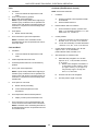
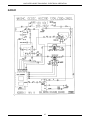
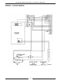
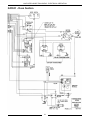
1
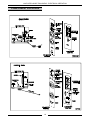
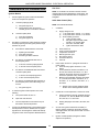
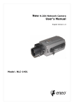
SERVICE MANUAL
HALF-SIZE
CONVECTION OVENS
ELECTRIC AND GAS
MODEL
ML
ELECTRIC
ECO2D
114570
ECO2C
114572
GAS
GCO2D
114569
GCO2C
114571
GCO2D Shown
- NOTICE This Manual is prepared for the use of trained Vulcan Service
Technicians and should not be used by those not properly
qualified. If you have attended a Vulcan Service School for this
product, you may be qualified to perform all the procedures
described in this manual.
This manual is not intended to be all encompassing. If you have
not attended a Vulcan Service School for this product, you should
read, in its entirety, the repair procedure you wish to perform to
determine if you have the necessary tools, instruments and skills
required to perform the procedure. Procedures for which you do
not have the necessary tools, instruments and skills should be
performed by a trained Vulcan Service Technician.
Reproduction or other use of this Manual, without the express
written consent of Vulcan-Hart, is prohibited.
A product of VULCAN-HART
Form 24575 (12/96)
LOUISVILLE, KY 40201-0696
HALF-SIZE CONVECTION OVENS
TABLE OF CONTENTS
GENERAL . . . . . . . . . . . . . . . . . . . . . . . . . . . . . . . . . . . . . . . . . . . . . . . . . . . . . . . . . . . . . . . . . . . . . . . . . . . . .
Introduction . . . . . . . . . . . . . . . . . . . . . . . . . . . . . . . . . . . . . . . . . . . . . . . . . . . . . . . . . . . . . . . . . . . . . . .
Specifications . . . . . . . . . . . . . . . . . . . . . . . . . . . . . . . . . . . . . . . . . . . . . . . . . . . . . . . . . . . . . . . . . . . . .
Gas Ovens . . . . . . . . . . . . . . . . . . . . . . . . . . . . . . . . . . . . . . . . . . . . . . . . . . . . . . . . . . . . . . . .
Electric Ovens . . . . . . . . . . . . . . . . . . . . . . . . . . . . . . . . . . . . . . . . . . . . . . . . . . . . . . . . . . . . .
Tools . . . . . . . . . . . . . . . . . . . . . . . . . . . . . . . . . . . . . . . . . . . . . . . . . . . . . . . . . . . . . . . . . . . . . . . . . . . .
3
3
3
3
3
3
REMOVAL AND REPLACEMENT OF PARTS . . . . . . . . . . . . . . . . . . . . . . . . . . . . . . . . . . . . . . . . . . . . . . . . . 4
Covers and Panels . . . . . . . . . . . . . . . . . . . . . . . . . . . . . . . . . . . . . . . . . . . . . . . . . . . . . . . . . . . . . . . . . 4
Control Panel Components . . . . . . . . . . . . . . . . . . . . . . . . . . . . . . . . . . . . . . . . . . . . . . . . . . . . . . . . . . . 5
Blower And/or Blower Motor . . . . . . . . . . . . . . . . . . . . . . . . . . . . . . . . . . . . . . . . . . . . . . . . . . . . . . . . . . . 6
Oven Door . . . . . . . . . . . . . . . . . . . . . . . . . . . . . . . . . . . . . . . . . . . . . . . . . . . . . . . . . . . . . . . . . . . . . . . . 7
Door Switch . . . . . . . . . . . . . . . . . . . . . . . . . . . . . . . . . . . . . . . . . . . . . . . . . . . . . . . . . . . . . . . . . . . . . . . 8
Heat Exchanger (Gas Ovens) . . . . . . . . . . . . . . . . . . . . . . . . . . . . . . . . . . . . . . . . . . . . . . . . . . . . . . . . . 8
Burner (Gas Ovens) . . . . . . . . . . . . . . . . . . . . . . . . . . . . . . . . . . . . . . . . . . . . . . . . . . . . . . . . . . . . . . . . . 9
Gas Valve (Gas Ovens) . . . . . . . . . . . . . . . . . . . . . . . . . . . . . . . . . . . . . . . . . . . . . . . . . . . . . . . . . . . . . . 9
Heating Elements (Electric Ovens) . . . . . . . . . . . . . . . . . . . . . . . . . . . . . . . . . . . . . . . . . . . . . . . . . . . . 10
SERVICE PROCEDURES AND ADJUSTMENTS . . . . . . . . . . . . . . . . . . . . . . . . . . . . . . . . . . . . . . . . . . . . . .
Temperature Probe Test (All Models) . . . . . . . . . . . . . . . . . . . . . . . . . . . . . . . . . . . . . . . . . . . . . . . . . .
Verification of Spark at Spark Probe . . . . . . . . . . . . . . . . . . . . . . . . . . . . . . . . . . . . . . . . . . . . . . . . . . .
Gas Pressure Adjustment . . . . . . . . . . . . . . . . . . . . . . . . . . . . . . . . . . . . . . . . . . . . . . . . . . . . . . . . . . .
Spark Ignition Control Test . . . . . . . . . . . . . . . . . . . . . . . . . . . . . . . . . . . . . . . . . . . . . . . . . . . . . . . . . .
Electronic Control . . . . . . . . . . . . . . . . . . . . . . . . . . . . . . . . . . . . . . . . . . . . . . . . . . . . . . . . . . . . . . . . .
Solid State Control Test . . . . . . . . . . . . . . . . . . . . . . . . . . . . . . . . . . . . . . . . . . . . . . . . . . . . . . . . . . . . .
Solid State Control Calibration . . . . . . . . . . . . . . . . . . . . . . . . . . . . . . . . . . . . . . . . . . . . . . . . . . . . . . . .
Door Switch Adjustment . . . . . . . . . . . . . . . . . . . . . . . . . . . . . . . . . . . . . . . . . . . . . . . . . . . . . . . . . . . . .
Door Reversal . . . . . . . . . . . . . . . . . . . . . . . . . . . . . . . . . . . . . . . . . . . . . . . . . . . . . . . . . . . . . . . . . . . .
Door Adjustment . . . . . . . . . . . . . . . . . . . . . . . . . . . . . . . . . . . . . . . . . . . . . . . . . . . . . . . . . . . . . . . . . .
Blower Adjustment . . . . . . . . . . . . . . . . . . . . . . . . . . . . . . . . . . . . . . . . . . . . . . . . . . . . . . . . . . . . . . . . .
Element Test . . . . . . . . . . . . . . . . . . . . . . . . . . . . . . . . . . . . . . . . . . . . . . . . . . . . . . . . . . . . . . . . . . . . .
11
11
11
12
12
13
14
14
15
16
17
17
17
ELECTRICAL OPERATION . . . . . . . . . . . . . . . . . . . . . . . . . . . . . . . . . . . . . . . . . . . . . . . . . . . . . . . . . . . . . .
Component Function . . . . . . . . . . . . . . . . . . . . . . . . . . . . . . . . . . . . . . . . . . . . . . . . . . . . . . . . . . . . . . .
Component Location . . . . . . . . . . . . . . . . . . . . . . . . . . . . . . . . . . . . . . . . . . . . . . . . . . . . . . . . . . . . . . .
Sequence of Operation . . . . . . . . . . . . . . . . . . . . . . . . . . . . . . . . . . . . . . . . . . . . . . . . . . . . . . . . . . . . .
Ignition Module . . . . . . . . . . . . . . . . . . . . . . . . . . . . . . . . . . . . . . . . . . . . . . . . . . . . . . . . . . . .
Gas Oven . . . . . . . . . . . . . . . . . . . . . . . . . . . . . . . . . . . . . . . . . . . . . . . . . . . . . . . . . . . . . . . .
Electric Oven . . . . . . . . . . . . . . . . . . . . . . . . . . . . . . . . . . . . . . . . . . . . . . . . . . . . . . . . . . . . .
Schematics Gas Ovens . . . . . . . . . . . . . . . . . . . . . . . . . . . . . . . . . . . . . . . . . . . . . . . . . . . . . . . . . . . . .
GCO2D . . . . . . . . . . . . . . . . . . . . . . . . . . . . . . . . . . . . . . . . . . . . . . . . . . . . . . . . . . . . . . . . .
GCO2C . . . . . . . . . . . . . . . . . . . . . . . . . . . . . . . . . . . . . . . . . . . . . . . . . . . . . . . . . . . . . . . . .
Wiring Diagram - Gas Ovens . . . . . . . . . . . . . . . . . . . . . . . . . . . . . . . . . . . . . . . . . . . . . . . . . . . . . . . . .
GCO2D . . . . . . . . . . . . . . . . . . . . . . . . . . . . . . . . . . . . . . . . . . . . . . . . . . . . . . . . . . . . . . . . .
GCO2C . . . . . . . . . . . . . . . . . . . . . . . . . . . . . . . . . . . . . . . . . . . . . . . . . . . . . . . . . . . . . . . . .
Schematic-Electric Ovens . . . . . . . . . . . . . . . . . . . . . . . . . . . . . . . . . . . . . . . . . . . . . . . . . . . . . . . . . . .
ECO2D . . . . . . . . . . . . . . . . . . . . . . . . . . . . . . . . . . . . . . . . . . . . . . . . . . . . . . . . . . . . . . . . .
ECO2C . . . . . . . . . . . . . . . . . . . . . . . . . . . . . . . . . . . . . . . . . . . . . . . . . . . . . . . . . . . . . . . . .
Wiring Diagram Electric Ovens . . . . . . . . . . . . . . . . . . . . . . . . . . . . . . . . . . . . . . . . . . . . . . . . . . . . . . .
ECO2D . . . . . . . . . . . . . . . . . . . . . . . . . . . . . . . . . . . . . . . . . . . . . . . . . . . . . . . . . . . . . . . . .
ECO2C . . . . . . . . . . . . . . . . . . . . . . . . . . . . . . . . . . . . . . . . . . . . . . . . . . . . . . . . . . . . . . . . .
18
18
19
20
20
20
23
26
26
27
28
28
30
32
32
33
34
34
36
TROUBLESHOOTING . . . . . . . . . . . . . . . . . . . . . . . . . . . . . . . . . . . . . . . . . . . . . . . . . . . . . . . . . . . . . . . . . . 38
Electric Ovens . . . . . . . . . . . . . . . . . . . . . . . . . . . . . . . . . . . . . . . . . . . . . . . . . . . . . . . . . . . . . . . . . . . . 38
Gas Ovens . . . . . . . . . . . . . . . . . . . . . . . . . . . . . . . . . . . . . . . . . . . . . . . . . . . . . . . . . . . . . . . . . . . . . . 39
© VULCAN 1996
2
HALF-SIZE CONVECTION OVENS - GENERAL
GENERAL
INTRODUCTION
General
This manual will cover half-size electric and gas convection ovens that use either a solid state control or an electronic
control.
Procedures in this manual are applicable to both gas and electric ovens unless specified.
SPECIFICATIONS
GAS OVENS
GAS DATA
INPUT BTU/HR
ELECTRICAL DATA
MANIFOLD PRESSURE
LOAD
(Watts)
AMP/LINE
Natural
Propane
Natural
Propane
120V
Single Oven
2500
2500
3.5" W.C.
10"W.C.
950
8
Stacked Oven
5000
5000
3.5" W.C
10"W.C.
1900
16
ELECTRIC OVENS
NOMINAL AMPS PER LINE WIRE
TOTAL
KW
3-PHASE LOADING
(KW PER PHASE)
3 PHASE
208V
1 PHASE
240V
L1-L2
L2-L3
L1-L3
L1
L2
L3
L1
L2
L3
208V
240V
Single Oven
5.5
2.5
0
3.0
22.9
10.4
12.5
19.9
9.0
10.9
26.5
23.0
Stacked
Ovens
11.0
5.0
0
6.0
45.8
20.8
25.0
39.7
18.0
21.7
52.9
45.9
TOOLS
•
•
•
•
Standard set of hand tools
VOM with AC current tester (Any VOM with a sensitivity of at least 20,000 ohms per volt can be used.)
Temperature tester
Manometer (Gas Ovens)
3
HALF-SIZE CONVECTION OVENS - REMOVAL AND REPLACEMENT OF PARTS
REMOVAL AND REPLACEMENT OF PARTS
COVERS AND PANELS
Right Side Panel
WARNING: DISCONNECT THE ELECTRICAL
POWER TO THE MACHINE AT THE MAIN CIRCUIT
BOX. PLACE A TAG ON THE CIRCUIT BOX
INDICATING THE CIRCUIT IS BEING SERVICED.
WARNING: SHUT OFF THE GAS BEFORE
SERVICING THE UNIT. (When applicable)
1.
Remove the three screws which secure the right
side of the control panel.
2.
Loosen the two screws on the right side of the top
front cover.
3.
Remove the remaining eight screws securing the
right side panel.
4.
Pull the right side panel out at the bottom then
down to remove.
5.
Reverse the procedure to install.
Top Front Cover
1.
2.
The top front cover is secured with four screws,
two on each side of cover. Remove these screws
then pull cover off unit.
Reverse the procedure to install.
Control Panel
1.
On gas models, remove the handle from the
manual gas valve.
2.
Remove the three screws from the left front and
loosen the three screws on the right side of the
control panel.
3.
Pull the panel away from the oven.
4.
Unplug the lead wires to the control panel
components and disconnect the temperature
probe leads.
5.
Reverse the procedure to install.
4
HALF-SIZE CONVECTION OVENS - REMOVAL AND REPLACEMENT OF PARTS
CONTROL PANEL
COMPONENTS
Removable Components
Listed on the illustration.
Procedure
WARNING: UNPLUG UNIT BEFORE SERVICING.
1.
Remove the control panel as outlined under
"COVERS AND PANELS".
5
2.
Disconnect the wire leads at the component to be
replaced.
3.
Remove the component.
4.
Reverse the procedure to install the new
component, then check oven for proper
operation.
HALF-SIZE CONVECTION OVENS - REMOVAL AND REPLACEMENT OF PARTS
BLOWER AND/OR BLOWER
MOTOR
8.
A.
B.
C.
D.
WARNING: UNPLUG UNIT BEFORE SERVICING.
1.
Remove racks and the right rack support.
2.
Remove baffle panel by lifting up and out.
3.
For gas ovens only, remove the heat exchanger
as outlined under “HEAT EXCHANGER”.
4.
Loosen set screws on blower hub.
Disconnect the wire leads to the motor.
9.
P1 (purple) to wire# 11
Orange (Low speed) to wire# 12
Blue (high speed) to wire# 13
Red wires connected together.
Remove the bolts that secure the motor to the
motor mounting plate and remove the motor from
the oven.
10. Place new motor in position on the motor
mounting plate and route the wiring through the
grommet in the component panel.
11. Install mounting pads and bolts. DO NOT tighten
mounting bolts.
12. Slide the blower onto motor shaft until hub is
flush with end of shaft and tighten set screws.
13. Adjust motor position until blower is parallel to
oven cavity wall with a spacing of ¼" as outlined
under "BLOWER ADJUSTMENT" in "SERVICE
PROCEDURES AND ADJUSTMENTS".
5.
Remove blower from motor shaft. You may have
to use a bearing puller.
6.
If the blower only is to be replaced, reverse
procedure to install and check blower to be
parallel with the motor mounting plate as outlined
under "BLOWER ADJUSTMENT" in "SERVICE
PROCEDURES AND ADJUSTMENTS”. If the
motor is to be replaced, continue to step 7.
7.
Remove the right side panel.
14. Install baffle panel, rack guides and racks.
6
HALF-SIZE CONVECTION OVENS - REMOVAL AND REPLACEMENT OF PARTS
OVEN DOOR
Disassembly
Removal
1.
Open the door.
WARNING: UNPLUG UNIT BEFORE SERVICING.
2.
Remove the door handle and latch plate.
1.
Remove the top front cover as outlined under
"COVERS AND PANELS".
3.
Remove the screws which secure the inner and
outer door panels to the door frame.
2.
Remove the door switch lever from the door
shaft.
3.
Remove the door switch bracket.
4.
While supporting the door, remove the bearing,
door plate and spacer.
4.
Remove the inner and outer door panel.
5.
Remove the four screws and lift the window
assembly out.
NOTE: Use high temperature silicone between
the window and the door panel.
5.
Lift the door from the lower bearing.
6.
Reverse procedure to install door assembly and
check for proper adjustment as outlined under
"DOOR ADJUSTMENT" and "DOOR SWITCH
ADJUSTMENT" in "SERVICE PROCEDURES
AND ADJUSTMENTS".
6.
7
Reverse the procedure to install the new window
and adjust the door as outlined under “DOOR
ADJUSTMENT”.
HALF-SIZE CONVECTION OVENS - REMOVAL AND REPLACEMENT OF PARTS
DOOR SWITCH
HEAT EXCHANGER (GAS
OVENS)
WARNING: UNPLUG UNIT BEFORE SERVICING.
1.
Remove the top front cover as outlined under
"COVERS AND PANELS".
WARNING: UNPLUG UNIT BEFORE SERVICING.
2.
Disconnect the leads to the door switch.
WARNING: SHUT OFF THE GAS BEFORE
SERVICING THE UNIT.
3.
Remove the switch which is secured by two
screws.
1.
Remove racks and the right rack support.
2.
Remove baffle panel by lifting up and out.
3.
Remove the screws that secure the heat
exchanger and remove it from the oven.
4.
Reverse procedure to install.
4.
Reverse the procedure to install the new
switch.
5.
Adjust the door switch as outlined under
"DOOR SWITCH ADJUSTMENT" in
"SERVICE PROCEDURES AND
ADJUSTMENTS".
8
HALF-SIZE CONVECTION OVENS - REMOVAL AND REPLACEMENT OF PARTS
BURNER (GAS OVENS)
GAS VALVE (GAS OVENS)
WARNING: UNPLUG UNIT BEFORE SERVICING.
WARNING: UNPLUG UNIT BEFORE SERVICING.
WARNING: SHUT OFF THE GAS BEFORE
SERVICING THE UNIT.
WARNING: SHUT OFF THE GAS BEFORE
SERVICING THE UNIT.
WARNING: ALL GAS JOINTS DISTURBED
DURING SERVICING MUST BE CHECKED FOR
LEAKS. CHECK WITH A SOAP AND WATER
SOLUTION (BUBBLES). DO NOT USE AN OPEN
FLAME.
1.
Remove racks and the right rack support.
2.
Remove baffle panel by lifting up and out.
3.
Remove the right side panel as outlined under
“COVERS AND PANELS”.
A.
CHECK ALL JOINTS PRIOR TO THE
GAS VALVE BEFORE LIGHTING UNIT.
Disconnect the lead wires to the electrode
assembly.
B.
CHECK ALL JOINTS BEYOND GAS
VALVE AFTER UNIT IS LIT.
4.
5.
6.
Remove the heat exchanger as outlined under
“HEAT EXCHANGER”.
1.
Remove the right side panel and control panel
as outlined under “COVERS AND PANELS”.
Remove the screws from the burner bracket
and pull the burner into the oven cavity.
2.
Disconnect the lead wires at the gas valve.
7.
Remove the screws that secure the electrodes
to the burner bracket.
3.
Disconnect the gas line fitting going to the
burner at the top of the gas valve.
8.
Reverse procedure to install.
4.
Remove the gas valve from the nipple between
the it and the manual gas valve.
5.
Reverse procedure to install.
6.
Adjust the gas valve as outlined under “GAS
PRESSURE ADJUSTMENT”.
NOTE: When installed, the electrodes are
positioned toward the front of the oven.
9
HALF-SIZE CONVECTION OVENS - REMOVAL AND REPLACEMENT OF PARTS
HEATING ELEMENTS
(ELECTRIC OVENS)
TEMPERATURE PROBE
Procedure
WARNING: DISCONNECT THE ELECTRICAL
POWER TO THE MACHINE AT THE MAIN
CIRCUIT BOX. PLACE A TAG ON THE CIRCUIT
BOX INDICATING THE CIRCUIT IS BEING
SERVICED.
1.
Remove racks and the right rack support.
2.
Remove baffle panel by lifting up and out.
3.
Remove the right side panel as outlined under
“COVERS AND PANELS”.
4.
Disconnect the lead wires to the heating
elements.
5.
Remove the screws from the clamps that
secure the heating element assembly.
WARNING: UNPLUG UNIT BEFORE SERVICING.
1.
Remove the control panel as outlined under
"COVERS AND PANELS".
2.
Disconnect the probe leads at the temperature
control.
3.
Remove probe from the probe guard and push
it thru the oven wall into the control panel area.
NOTE: When installing, only the metal surface of
the probe should be inserted into the probe guard.
NOTE: The probe may have to be inserted at an
angle. The hole in the inside oven cavity wall may
not line up straight with the oven cavity outer shell.
6.
Pull the top of the heating element assembly
into the oven cavity until the ends of the
elements are inside the oven cavity. Lift up and
remove the lower clamp from between the side
wall and the bottom of the oven cavity.
7.
Remove the clamps from the heating element
assembly and replace the element(s).
8.
Reverse procedure to install.
10
4.
Reverse the procedure to install the new probe.
5.
Adjust the temperature control as outlined
under "TEMPERATURE CONTROL
CALIBRATION" in "SERVICE PROCEDURES
AND ADJUSTMENTS".
HALF-SIZE GAS CONVECTION OVENS - SERVICE PROCEDURES AND ADJUSTMENTS
SERVICE PROCEDURES AND ADJUSTMENTS
WARNING: CERTAIN PROCEDURES IN THIS SECTION REQUIRE ELECTRICAL TEST OR
MEASUREMENTS WHILE POWER IS APPLIED TO THE MACHINE. EXERCISE EXTREME CAUTION AT ALL
TIMES. IF TEST POINTS ARE NOT EASILY ACCESSIBLE, DISCONNECT POWER, ATTACH TEST
EQUIPMENT AND REAPPLY POWER TO TEST.
TEMPERATURE PROBE
TEST (ALL MODELS)
VERIFICATION OF SPARK
AT SPARK PROBE
WARNING: UNPLUG UNIT BEFORE SERVICING.
WARNING: UNPLUG UNIT BEFORE SERVICING.
1.
Remove the right side panel as outlined under
"COVERS AND PANELS".
WARNING: SHUT OFF THE GAS BEFORE
SERVICING THE UNIT.
2.
Remove the probe lead wires from the
electronic control.
1.
3.
Test the probe with an ohmmeter.
TEMPERATURE
in (F
Remove the right side panel and control panel
as outlined under “COVERS AND PANELS”.
2. Disconnect the high voltage lead from the
electrode.
WARNING: DO NOT HOLD THE WIRE WITH
YOUR HANDS FOR THIS TEST. THE MANUAL
GAS VALVE MUST BE CLOSED.
RESISTANCE
in ±10%
3.
77
90000
240
4077
260
3016
280
2266
300
1726
320
1332
340
1041
360
822
380
656
400
529
425
424
450
334
475
266
Clamp the wire in such a manner that the end
of the wire is 3/16" from the frame of the oven.
NOTE: It is critical that the wire be held 3/16" away
from the oven or sparking may not occur even
though the probe circuits are functioning properly.
WARNING: THE FOLLOWING STEPS REQUIRE
POWER TO BE APPLIED TO THE UNIT DURING
THE TEST. USE EXTREME CAUTION AT ALL
TIMES.
4.
5.
6.
11
Plug the unit in and set the temperature
controller to the maximum setting.
Turn the power switch on.
Sparking should occur after a 15 second purge
time. Arcing from the lead wire to the oven
frame should be observed at this time.
HALF-SIZE GAS CONVECTION OVENS - SERVICE PROCEDURES AND ADJUSTMENTS
GAS PRESSURE
ADJUSTMENT
WARNING: UNPLUG UNIT BEFORE SERVICING.
WARNING: SHUT OFF THE GAS BEFORE
SERVICING THE UNIT.
1.
Remove the right side panel and control panel
as outlined under “COVERS AND PANELS”.
2.
Remove the plug from the test port and install
the manometer.
GAS TYPE
SETTING AT OUTPUT
OF GAS VALVE
Natural
3.5 inches W.C.
Propane
10 inches W.C.
NOTE: If input pressure is below 4.0 (Natural) or
10.5 (Propane) inches W.C., the desired output
cannot be obtained and the oven will overate at a
lower BTU.
SPARK IGNITION CONTROL
TEST
WARNING: THE FOLLOWING STEPS REQUIRE
POWER TO BE APPLIED TO THE UNIT DURING
THE TEST. USE EXTREME CAUTION AT ALL
TIMES.
WARNING: UNPLUG UNIT BEFORE SERVICING.
3.
Plug in the unit and turn on the gas.
No Gas Ignition & No Sparking
4.
Set the temperature control to the highest
setting and turn the power switch on. The
burner must be lit while adjusting the pressure.
1.
Remove the right side panel as outlined under
“COVERS AND PANELS”.
5.
Turn the adjustment screw to obtain the proper
gas pressure.
2.
Plug in the unit and set the temperature
controller to 350°.
3.
Turn the power switch on.
4.
Check for 24 VAC between the power terminal
and ground terminal.
NOTE: Verify that the ground terminal is connected
to the oven ground.
A.
B.
If 24 VAC is present, replace the spark
ignition control.
If 24 VAC is not present, check the
transformer, temperature controller, and
switches.
No gas ignition - sparking occurs
1.
2.
•
•
Turn screw clockwise to increase pressure.
Turn screw counterclockwise to decrease
pressure.
Remove the right side panel as outlined under
“COVERS AND PANELS”.
Plug in the unit and set the temperature
controller to 350°.
3.
Turn the power switch on.
4.
Check for 24 VAC between the gas valve
terminal and the ground terminal. The voltage
should be present after the 15 second purge
and during the 10 second ignition period.
A.
B.
12
If 24 VAC is present, check the gas valve
and gas supply.
If 24 VAC is not present, replace the spark
ignition control.
HALF-SIZE GAS CONVECTION OVENS - SERVICE PROCEDURES AND ADJUSTMENTS
ELECTRONIC CONTROL
SPECIAL KEY FUNCTIONS - To activate these
functions press the specified keys while turning the
oven on. You can not toggle between functions.
Each function has to be entered from the off
position.
NOTE: There are four hidden keys on the control.
See diagram following the table.
HOLD KEYS
1&3
FUNCTION
Calibration Mode
4&9
Change between (C & (F
6&8
Display test
CALIBRATE OVEN - Perform Calibration at 350(F
1.
Place a thermocouple near the geometric
center of the oven cavity.
2.
Cycle oven until the cavity temperature stabilizes. (usually 3 cycles)
3.
Turn the oven off.
4.
Enter the calibration mode.
5.
Compare the set temperature to the measured
temperature.
6.
Adjust the temperature on the display to match
the measured temperature.
7.
Press key 3 to store the calibration information.
DISPLAY TEST - The control will cycle through a
continuous test until the oven is turned off. Each
segment of the displays will be lit in sequence, each
LED in order and then each digit will light.
ERROR CODES
CODES
CONDITIONS
E-01
High Limit Error - Check open probe.
E-02
Low Limit Error - check for 6 VAC from transformer.
Check control pins 1-2 for 12 VAC & pins 2-3.
E-03
Control compartment ambient temperature is above 215(F
E-04
Control compartment ambient temperature is below 32(F
13
HALF-SIZE GAS CONVECTION OVENS - SERVICE PROCEDURES AND ADJUSTMENTS
SOLID STATE CONTROL
CALIBRATION
SOLID STATE CONTROL
TEST
NOTE: Oven temperature must be below 450(F.
1.
Place a thermocouple in the geometric center
of the oven cavity.
1.
Remove the screws from the control panel and
pull the control panel away from the oven to
access the control wiring.
2.
Set the On-Off-Cool Down switch to ON.
3.
Set the temperature control to 350 degrees F.
2.
Place a thermocouple in the geometric center
of the oven cavity.
4.
3.
Set the temperature to the maximum setting.
Allow the oven to cycle until the oven
temperature stabilizes. (cycle at least three
times)
4.
Turn the power switch to ON.
5.
Record the temperature at which the HEAT
LIGHT goes off and on.
A.
6.
Check for at least two complete heating
cycles.
Calculate the differential by subtracting the
temperature indicated when the heat light
comes on from the temperature indicated when
the heat light goes out.
Differential = Heat light OFF - Heat light ON.
5.
Check for supply voltage across:
200-240 volts - pin 10 to pin 6
120 volts - pin 9 to pin 6
A.
B.
6.
A.
If correct, proceed to step 7.
If incorrect, go to step 6.
If correct, proceed to step 7.
If incorrect, problem is not with the
temperature control. Return to Troubleshooting Guide.
7.
Turn the temperature control to the minimum
setting.
NOTE: Oven temperature must be above 300(F.
8.
Calculate the average temperature by adding
the temperature indicated when the heat light
goes out to the temperature indicated when the
heat light comes on and dividing this answer by
2.
[Temp.(light off)+ Temp.(light on)] ÷ 2 = Average
Temperature
Check for zero (O) Volts across:
200-240 volts - pin 6 to pin 10
120 volt - pin 6 to pin 9
A. If correct the problem is not with the
temperature control. Return to Troubleshooting Guide.
B.
The differential calculated should be
less than 20 degrees F.
(1) If the differential is more than 20
degrees F, check temperature
probe and temperature control
board as outlined under
"TEMPERATURE PROBE
TEST" and "SOLID STATE
CONTROL TEST".
Check for supply voltage across:
200-240 volts - pin 7 to pin 10 and pin 8 to pin
10
120 volt - pin 7 to pin 9 and pin 8 to pin 9
A.
B.
7.
Example: 360 (light out) - 340 (light on) = 20( F
differential.
Example: (360 + 340) ÷ 2 = 700 ÷ 2 = 350( F
average temperature
If incorrect, replace the temperature
control.
14
HALF-SIZE GAS CONVECTION OVENS - SERVICE PROCEDURES AND ADJUSTMENTS
8.
If the average temperature differs more than 10
degrees F from the dial settings:
A.
Pencil mark the knob pointer position as a
reference point on the control panel next
to the dial plate.
B.
Remove the temperature control knob.
C.
DOOR SWITCH
ADJUSTMENT
WARNING: DISCONNECT THE ELECTRICAL
POWER TO THE MACHINE AT THE MAIN
CIRCUIT BOX. PLACE A TAG ON THE CIRCUIT
BOX INDICATING THE CIRCUIT IS BEING
SERVICED.
1.
Remove the upper front cover as outlined
under "COVERS AND PANELS".
2.
The door switch actuator should be operated by
the switch lever when the door is about ½" from
being closed.
3.
If adjustment is necessary, use the following
procedures.
Loosen the two dial plate mounting screws
and the temperature control mounting nut.
Loosen only enough to turn the dial plate.
D.
Rotate the dial plate until the temperature
calculated in step 7 is in line with the
pencil mark.
E.
If the above adjustment cannot be
obtained, check temperature probe and
temperature control board as outlined
under "TESTING TEMPERATURE
CONTROL BOARD".
4.
15
A.
Loosen the two switch mounting screws.
B.
Adjust the switch bracket to obtain the
correct setting as outlined in step 2.
C.
Tighten the two switch bracket mounting
screws.
D.
If the adjustment can not be obtained by
moving the switch, you can bend the tab
of the actuator lever.
Install the upper front cover.
HALF-SIZE GAS CONVECTION OVENS - SERVICE PROCEDURES AND ADJUSTMENTS
DOOR REVERSAL
7.
WARNING: DISCONNECT THE ELECTRICAL
POWER TO THE MACHINE AT THE MAIN
CIRCUIT BOX. PLACE A TAG ON THE CIRCUIT
BOX INDICATING THE CIRCUIT IS BEING
SERVICED.
1.
Remove the door switch from the switch
mounting bracket.
A.
Use the other set of holes in the mounting
bracket to mount the switch.
B.
Place the switch insulation pad on the
mounting bracket.
C.
Install the switch onto the mounting
bracket.
Remove the door as outlined under “OVEN
DOOR”.
A.
Remove the door strike plate from the top
of the door.
B.
Rotate the door 180°. The top of the door
is now the bottom.
C.
Install the door strike on the new top of the
door. Use the screws removed to install
the strike plate to fill the holes on the
bottom of the door.
2.
Remove the bottom door bushing and antirotation plate.
3.
Remove the knockout from the lower sill cover.
4.
Install the plug button in the old door bushing
hole in the lower sill cover.
5.
Install the bottom door bushing and antirotation plate.
6.
Remove the catch assembly from the oven.
A.
B.
Move the door catch to the opposite side
of the door catch channel.
Install the door catch assembly to the
opposite side of the top sill.
8.
Install the door in the lower door bushing.
9.
Install the top door bushing and door switch
mounting plate to the new position on the upper
sill.
10. Adjust the door as outlined under “DOOR
ADJUSTMENT”.
11. Adjust the door switch as outlined under
“DOOR SWITCH ADJUSTMENT”.
12. Replace the top front cover and check the oven
for proper operation.
16
HALF-SIZE GAS CONVECTION OVENS - SERVICE PROCEDURES AND ADJUSTMENTS
DOOR ADJUSTMENT
BLOWER ADJUSTMENT
WARNING: UNPLUG UNIT BEFORE SERVICING.
1.
2.
WARNING: DISCONNECT THE ELECTRICAL
POWER TO THE MACHINE AT THE MAIN
CIRCUIT BOX. PLACE A TAG ON THE CIRCUIT
BOX INDICATING THE CIRCUIT IS BEING
SERVICED.
The door should be parallel with the face of the
oven cavity.
If adjustment is needed:
A.
B.
Remove the top front cover as outlined
under “COVERS AND PANELS” in
“REMOVAL AND REPLACEMENT OF
PARTS”.
Loosen the screws that secure the door
support and move the door in the slot until
it is parallel with the face of the oven
cavity.
1.
Remove rack and rack supports.
2.
Remove baffle panel by lifting up and out.
3.
Check the blower. It should be ¼" away from
and parallel to the oven wall. If not, proceed to
step 4.
4.
Remove the right side panel as outlined under
“COVERS AND PANELS”.
5.
To adjust the blower at the sides (front and rear
of oven cavity), loosen the motor mounting
bolts and move the motor until the ¼" gap is
obtained.
6.
To adjust the blower at the top and bottom,
place shims between the motor mounting
bracket and the mounting base.
7.
Reverse the procedure to install.
HEATING ELEMENT TEST
C.
Tighten the screws and install the top front
cover.
Test each rod in the element assembly.
Values in the table are nominal (± 10%).
17
VOLTAGE
WATTS
AMPS
RESISTANCE
208
2500
12
17.33
240
2500
10.4
23.1
HALF-SIZE CONVECTION OVENS - ELECTRICAL OPERATION
ELECTRICAL OPERATION
COMPONENT FUNCTION
POWER SWITCH . . . . . . . . . . . . . Controls power to oven.
COOLDOWN SWITCH . . . . . . . . . Prevents heaters from operating and allows fan to run. (On some solid state
control models, this switch is combined with the power switch)
FAN SPEED SWITCH . . . . . . . . . . Controls speed of oven cavity blower motor. (Electric ovens)
SOLID STATE CONTROL . . . . . . . Controls oven temperature.
TIMER . . . . . . . . . . . . . . . . . . . . . Signals end of timed baking. Does not shut heater or burner off. (Solid state
control)
ELECTRONIC CONTROL . . . . . . . Controls oven temperature, cook and hold mode, pulse mode and time.
BLOWER MOTOR . . . . . . . . . . . . Circulates air inside oven cavity. (Contains centrifugal switch for gas ovens)
(2 speed electric ovens)
DOOR SWITCH . . . . . . . . . . . . . . Allows heating of oven, only when the doors are closed.
TEMPERATURE PROBE . . . . . . . Senses temperature of oven cavity for the solid state control and electronic
control.
SOLID STATE RELAY . . . . . . . . . Controls power to blower motor. (Electronic Control)
TRANSFORMER . . . . . . . . . . . . . . Provides 12 and 6 VAC power. (Electronic Control)
TRANSFORMER . . . . . . . . . . . . . . Provides 24 VAC power to the spark ignition control if the centrifugal switch
(part of blower motor) is closed. (Gas Ovens)
GAS VALVE . . . . . . . . . . . . . . . . . Allows gas to flow to burner. (Gas ovens)
SPARK MODULE . . . . . . . . . . . . . Generates spark for burner ignition, monitors flame, controls 15 second
purge
time and 10 second ignition time and power to gas valve. (Gas ovens)
POWER LIGHT . . . . . . . . . . . . . . . Lit whenever the power switch is ON. (Solid state control)
HEAT LIGHT . . . . . . . . . . . . . . . . . Lit whenever burner or heaters are operating. (Solid state control)
NO IGNITION LIGHT . . . . . . . . . . Lit when sensor fails to detect flame. (Solid state control - Gas oven)
CONTACTOR . . . . . . . . . . . . . . . . Powers heater elements. (Electric ovens)
FUSE
. . . . . . . . . . . . . . . . . . . . . Protects control circuit. (Electric ovens)
18
HALF-SIZE CONVECTION OVENS - ELECTRICAL OPERATION
COMPONENT LOCATION
19
HALF-SIZE CONVECTION OVENS - ELECTRICAL OPERATION
Gas Oven
SEQUENCE OF OPERATION
NOTE: A combination of terminal numbers and wire
numbers will be used to describe the circuit paths. The
complete path will be described when a component is
energized.
Ignition Module
1.
24VAC supplied to ignition module as described
under oven sequence of operation
Solid State Control (Gas)
A.
15 second prepurge period
NOTE: Use GCO2D Schematic
1)
2)
B.
1.
Conditions
A.
Supply voltage to unit
1) L1 to power switch: wire #1; J1-1; wire #1
2) L2 to power switch: wire #2; J1-2; wire #2
3) Good chassis ground for:
a.
Ignition module: GND
b.
No ignition light: wire #48; GND;
wire #6; J1-6; wire #6; GND
c.
Gas valve: wire #48; GND;
d.
Ignition transformer: GND
B.
C.
D.
E.
F.
G.
H.
Power switch off
Oven at room temperature
Temperature control off
Manual gas valve open
Door switch closed
Cooldown switch off
Timer off
10 second spark period
1)
2)
2.
No-ignition light is on
Cavity blower motor removes any
residual gas from combustion chamber
Gas valve energized
No-ignition light is off
The flame is monitored by a DC voltage of at least 5
microamps passing from the ignitor probe through
the flame to ground.
A.
If the flame is detected before 10 seconds:
1)
2)
3)
B.
Sparking is terminated
Gas valve held open
Monitoring of flame continues
If a flame is not established after the 10
second spark period
2.
1)
2)
C.
If a flame is not established after the second
10 second spark period
1)
2)
D.
a second 15 second prepurge period
A second 10 second spark period
a third 15 second prepurge period
A third 10 second spark period
If a flame is not established after the third 10
second spark period, the module will go into
lock out
Power switch turned "on" (voltage at terminals of
power switch)
A. Power On lamp lights: wire #34/J1; wire
#41/37
B. Control powered: wire #34; wire #33/3; J1-3;
wire #3; door switch; wire #27/4; J1-4; wire
#4/36/35; terminal 8; terminal 9 (120 VAC) or
terminal 10 (200-240 VAC); wire #39/37
C. Blower motor energized: wire #34; wire #33/3;
J1-3; wire #3; door switch; wire #27/4; J1-4;
wire #4/11; J1-11; wire #11; wire #13/7; J1-7;
wire #7/37
1)
1)
3.
4.
No ignition light on
To reset the ignition module perform one of the
following
A. Turn power switch off; then on
B.
Open and close the door
C.
Turn the temperature control all the way off
then back to the set temperature
3.
If a flame is established then is extinguished before
the temperature control is satisfied, the no ignition
light will be on and the ignition module will attempt
to light the burner in the sequence described above.
20
Blower motor reaches operating speed,
blower motor centrifugal switch closes
Control set to cook temperature, contacts 6/7 close
A.
Ignition transformer primary powered: terminal
6; wire #9; J1-9; wire #9; BK/BL wire; WH/BK
wire; wire #7; J1-7; wire #7/37
B.
Heating lamp lights: terminal 6; wire #43; wire
#42/37
4.
24 VAC from ignition transformer secondary to
ignition module: transformer secondary wire #52;
centrifugal switch; wire #54; terminal 24V of control
module; GND
5.
Ignition module operates (see ignition module
sequence of operation)
HALF-SIZE CONVECTION OVENS - ELECTRICAL OPERATION
6.
Temperature is satisfied and control contacts 6/7
open
A. Heat light goes out.
B. Power removed from ignition transformer.
7.
Ignition module de-energized
A. Gas valve de-energized, gas supply to burner
off.
8.
Oven cycles on solid state control until power switch
is moved from the "on" position or the door is
opened.
Electronic Control (Gas)
NOTE: Use GCO2C Schematic
NOTE: A combination of terminal numbers and wire
numbers will be used to describe the circuit paths. The
complete path will be described when a component is
energized.
Heat
1.
NOTE: The blower motor, heat lamp and gas valve
are de-energized when the door is opened during
the heat mode.
Conditions.
A.
Supply voltage to unit.
1) L1 to power/cooldown switch: wire #1;
J1-1; wire #1
2) L2 to:
a.
Motor: wire #2; J1-2; wire #2; J1-7;
wire #7/13
b.
Primary of ignition transformer: wire
#2; J1-2; wire #2; J1-7; wire #7
c.
Primary of control transformer: wire
#2; J1-2; wire #2; J1-7; wire #7/97
3) Good chassis ground: ignition module
transformer
a.
Ignition module: GND
b.
Electronic control: terminal 8 of
control; J2-8; J1-6; wire #6; GND
c.
Gas valve: wire #48; GND
d.
Ignition transformer: GND
B.
C.
D.
E.
Power/cooldown “off".
Oven at room temperature.
Door switch closed.
Manual gas valve open.
Solid State Timer (Gas)
NOTE: Use GCO2D Schematic
NOTE: The timer is not connected to the heating circuit
and will not prevent the oven from heating when time
expires.
1.
Power switch on
2.
Time dialed into timer, contacts 1/3 close.
A.
3.
Timer motor energized: wire #34/64; timer
contacts 1/3; wht wire; wire #37
Time expires.
A.
Contacts 1/3 open
1) Timer motor de-energized
B.
Contacts 1/4 close
2.
Power/cooldown switch turned "on"
A.
4.
Buzzer sounds: wire #34/64; timer contacts 1/4; wire
#66; wire #65/37
5.
Timer turned to off.
A.
3.
Contacts 1/4 open
1) buzzer de-energized
Control powered from secondary of control
transformer:
A.
Cooldown (Gas/Solid State Control)
Control transformer primary powered: wire
#26/4; J1-4; wire #4/94; wire #97/7; J1-7; wire
#2; J1-2; wire #2; L2
B.
6 VAC - wire #16; J1-16; J2-3; J2-2; J1-15;
wire #15
12 VAC - wire #14; J1-14; J2-1; J2-2; J1-15;
wire #15
NOTE: Use GCO2D Schematic
4.
1.
2.
Conditions
A. Oven temperature needs to be lowered.
B. Power switch on
Control set to desired temperature
A.
Control verifies heat mode: 16 to 18 VDC
output on J2-11; J1-20; wire #20/21;
power/cooldown switch; contacts of switch are
open and no return voltage to J2-5
B.
Control verifies that door is closed: 16 to 18
VDC output on J2-11; J1-20; wire #20/27; door
switch; wire #3; J1-3; J2-4
Cooldown switch on
A.
Blower motor energized: power switch; wire
#34/33/36/11; J1-11; wire #11; wire #13/7; J17; wire #7/37; power switch
21
HALF-SIZE CONVECTION OVENS - ELECTRICAL OPERATION
5.
After verification of heat mode and door closed:
Cook and Hold
A.
Ignition transformer primary powered: wire
#26/43; J2-13; J2-15; J1-5; wire #5; BK/BL
wire; WH/BK wire; wire #7; J1-7; wire #2; J12; Wire #2; L2
1) 24 VAC from secondary of ignition
transformer to ignition module: wire #52;
centrifugal switch; wire #54; terminal 24V
of control module; GND
1.
Solid state relay energized: 16 to 18 VDC
output on J2-11; J1-20; wire #20; wire #19;
J1-19; J2-10
B.
1)
6.
7.
A.
Oven in preheat.
2.
A bake temperature and time is set.
3.
A hold temperature and time is set and start key
pressed.
4.
Oven cycles at set temperature.
NOTE: In pulse mode (initiated at the beginning of the
bake cycle), the blower motor is operated in 45 second
cycles, with the first cycle being off then 45 seconds on.
The pulse time cannot be longer than the bake time.
Blower motor energized: wire #26/4; J1-4;
wire #4/34; ss relay contacts; wire #9; J19; wire #11; J1-11; wire #11; wire #13/7;
J1-7; wire #2; J1-2; Wire #2; L2
a.
Conditions
5.
Blower motor reaches operating
speed, blower motor centrifugal
switch closes
Ignition module operates (see ignition module
sequence of operation)
6.
Oven cycles on electronic control until
power/cooldown switch is moved from the "on"
position, a different mode is selected or the door is
opened.
NOTE: The blower motor is de-energized and gas
valve closed when the door is opened while the oven
is in the heat mode.
Time expires in cook mode.
A.
Buzzer sounds (short beep).
B.
Control lowers temperature to hold
temperature.
Oven temperature reaches hold temperature.
A.
7.
Display counts up time and flashes "hold"
Oven continues to cycle at hold temperature until
oven is turned off or the hold function is turned off.
NOTE: The blower motor and gas valve are deenergized when the door is opened while the oven is
in the hold mode.
Cook
Cooldown (Gas/Electronic Control)
1.
Conditions
NOTE: Use GCO2C Schematic
A.
1.
Oven in preheat.
Conditions
2.
Temperature is set.
A.
3.
Time is set and start key pressed.
B.
4.
Oven cycles at set temperature.
2.
NOTE: In pulse mode (initiated at the beginning of
the bake cycle), the blower motor is operated in 45
second cycles, with the first cycle being off then 45
seconds on. The pulse time cannot be longer than
the bake time.
5.
Power/cooldown switch to cooldown
A.
3.
Control transformer primary powered: wire
#26/4; J1-4; wire #4/94; wire #97/7; J1-7; wire
#2; J1-2; wire #2; L2
Control powered from secondary of control
transformer:
Time expires.
A.
A.
Buzzer sounds continually until turned off.
B.
6.
Cooking completed, oven temperature needs
to be lowered.
Power/cooldown switch on
Oven continues to cycle at set temperature.
NOTE: The blower motor and gas valve are deenergized when the door is opened while the oven is
in the cook mode.
4.
22
6 VAC - wire #16; J1-16; J2-3; J2-2; J1-15;
wire #15
12 VAC - wire #14; J1-14; J2-1; J2-2; J1-15;
wire #15
Control verifies cooldown mode: 16 to 18 VDC
output on J2-11; J1-20; wire #20/21;
power/cooldown switch; wire #29; J2-5
HALF-SIZE CONVECTION OVENS - ELECTRICAL OPERATION
5.
After verification of cooldown mode:
A.
B.
C.
Solid state relay energized: 16 to 18 VDC
output on J2-11; J1-20; wire #20; wire #19;
J1-19; J2-10
1) Blower motor energized: wire #26/4; J14; wire #4/34; ss relay contacts;; wire # 9;
J1-9; wire #11; J1-11; wire #11; wire
#13/7; J1-7; wire #2; J1-2; wire #2; L2
B.
Control powered: wire #34; wire #33/3; J1-3;
wire #3; door switch; wire #27/4; J1-4; wire
#4/36/35; terminal 8 and 7; terminal 9 (120
VAC) or terminal 10 (200-240 VAC); wire
#39/37
C.
Blower motor energized: wire #34; wire #33/3;
J1-3; wire #3; door switch; wire #27/4; J1-4;
wire #4; motor speed switch; wire #11 high or
12 low ); J1-(11 high or 12 low); wire #(11 high
or 12 low); wire #13/7; J1-7; wire #7/37
Contactor coil will not be energized.
The door position signal is not read.
3.
Electric Oven
Control set to cook temperature contacts 6/7 close
A.
NOTE: A combination of terminal numbers and wire
numbers will be used to describe the circuit paths. The
complete path will be described when a component is
energized.
B.
Solid State Control (Elec)
4.
Heating elements energized
NOTE: Use ECO2D Schematic
A.
1.
B.
2.
Conditions.
A.
Fuses are good.
B.
Supply voltage to unit (three phase)
1)
L1 to power switch: wire #1; J1-1; fuse;
wire #1A and one side of heater contacts
C1: wire #61
2)
L2 to one side of heater contacts C2: wire
#62
3)
L3 to power switch: wire #2; J1-2; fuse;
wire #2A and one side of heater contacts
C31: wire #64
4)
Good chassis ground
5.
6.
Contactor coil energized: terminal 6; wire
#9; J1-9; wire #9/50; wire #52/7; J1-7;
wire #7/37
Heating lamp lights: terminal 6; wire #43;
wire #42/37
L1; wire #61; C1; Wire #70; wire #75; C3; Wire
#64; L3
L1; wire #61; C1; Wire #74; wire #71; C2; Wire
#62; L2
Oven reaches set temperature and control contacts
6/7 open
A.
Power removed from contactor coil
1) Heating elements de-energized
B.
Heating lamp goes out.
Oven cycles on solid state control until power switch
is moved from the "on" position or the door is
opened.
NOTE: The blower motor and heating elements are
de-energized when the door is opened and the oven
is in the heat mode.
C.
Power switch "off"
Solid State Timer (Elec)
D.
Oven at room temperature
NOTE: Use ECO2D Schematic
E.
Solid state control off
F.
Door switch closed
NOTE: The timer is not connected to the heating circuit
and will not prevent the oven from heating when time
expires.
G.
Fan speed switch in either position
1.
Power switch on
H.
Cooldown switch off
2.
Time dialed into timer, contacts 1/3 close.
J.
Timer off
A.
Power switch turned "on" (voltage at terminals of
power switch)
A.
3.
Power On lamp lights: wire #34/J1; wire
#41/37
23
Timer motor energized: wire #34/64; timer
contacts 1/3; wht wire; wire #37
Time expires.
A.
Contacts 1/3 open
1) Timer motor de-energized
B.
Contacts 1/4 close
HALF-SIZE CONVECTION OVENS - ELECTRICAL OPERATION
4.
Buzzer sounds: wire #34/64; timer contacts 1/4; wire
#66; wire #65/37
5.
Timer turned to off.
A.
C.
D.
E.
F.
Contacts 1/4 open
1) buzzer de-energized
2.
Power/cooldown switch turned "on"
A.
Cooldown (Elec/Solid State Control)
NOTE: Use ECO2D Schematic
1.
2.
Conditions
A.
A.
Cooking completed, oven temperature needs
to be lowered.
B.
Power switch on
4.
Cooldown switch on
A.
Blower motor energized: power switch; wire
#34/33/36/ motor speed switch; wire #11 high
or 12 low ); J1-(11 high or 12 low); wire #(11
high or 12 low); wire #13/7; J1-7; wire #7/37;
power switch
NOTE: Use ECO2C Schematic
5.
NOTE: A combination of terminal numbers and wire
numbers will be used to describe the circuit paths. The
complete path will be described when a component is
energized.
A.
Control verifies heat mode: 16 to 18 VDC
output on J2-11; J1-20; wire #20/21; J1-21;
power/cooldown switch; contacts of switch are
open and no return voltage to J2-5
B.
Control verifies that door is closed: 16 to 18
VDC output on J2-11; J1-20; wire #20/27; door
switch; wire #3; J1-3; J2-4
After verification of heat mode and door closed,
A.
Heat
Conditions
B.
A.
Fuses are good.
B.
Supply voltage to unit (three phase)
1)
2)
3)
4)
L1 to power/cooldown switch: wire #1;
J1-1; fuse; wire #1A/1 and one side of
heater contacts C1: wire #61
L2 to one side of heater contacts C2: wire
#62
L3 to:
a.
Motor: wire #2; J1-2; fuse; wire
#2A/7; J1-7; wire #7/13
6.
b.
7.
24
Solid state relay energized: 16 to 18 VDC
output on J2-11; J1-20; wire #20; wire #19;
J1-19; J2-10
1) Blower motor energized: wire #26/4; J14; wire #4/34; ss relay contacts;; wire #
(11 high or 12 low ); J1-(11 high or 12
low); wire #(11 high or 12 low); wire
#13/7; J1-7; wire #7/37
Contactor coil energized: wire #43; J2-13; J215; J1-5; wire #5; wire #50/7; J1-7; wire
#7/2A; fuse; J1-2; Wire #2; L3
1) Heating elements energized
a.
L1; wire #61; C1; Wire #70; wire
#75; C3; Wire #64; L3
b.
L1; wire #61; C1; Wire #74; wire
#71; C2; Wire #62; L2
Oven reaches set temperature
A.
Contactor coil: wire #2; J1-2; fuse;
wire #2A/7; J1-7; wire #7/50
c.
Primary of control transformer: wire
#2; J1-2; fuse; wire #2A/7; J1-7;
wire #7/97
d.
one side of heater contacts C3: wire
#64
Good chassis ground electronic control:
terminal 8 of control; J2-8; J1-6; wire #6;
GND
6 VAC - wire #16; J1-16; J2-3; J2-2; J1-15;
wire #15
12 VAC - wire #14; J1-14; J2-1; J2-2; J1-15;
wire #15
Control set to desired temperature
Electronic Control (Elec)
1.
Control transformer primary powered: wire
#26/4; J1-4; wire #4/94; wire #97/7; J1-7; wire
#7/2A; fuse; J1-2; wire #2; L3
Control powered from secondary of control
transformer:
B.
3.
Power/cooldown switch "off"
Oven at room temperature
Door switch closed
Fan speed switch in either position
Power removed from contactor coil
1) Heating elements de-energized
Oven cycles on electronic control until
power/cooldown switch is moved from the "on"
position or the door is opened.
NOTE: The blower motor and heating elements are
de-energized when the door is opened and the oven
is in the heat mode.
HALF-SIZE CONVECTION OVENS - ELECTRICAL OPERATION
Cook
Cooldown (Elec/Electronic Control)
1.
NOTE: Use ECO2C Schematic
2.
3.
Conditions
A. Oven has reached set temperature in heat
mode
Time is set and start key pressed.
Oven cycles at set temperature.
NOTE: In pulse mode (initiated at the beginning of
the bake cycle), the blower motor is operated in 45
second cycles, with the first cycle being off then 45
seconds on. The pulse time cannot be longer than
the bake time.
1.
Conditions
A.
B.
2.
Power/cooldown switch to cooldown
A.
4.
Time expires.
A. Buzzer sounds continually.
5.
Oven continues to cycle at set temperature.
3.
B.
Cook and Hold
1.
Oven has reached set temperature in heat
mode
2.
A bake temperature and time is set.
3.
A hold temperature and time is set and start key
pressed.
4.
Oven cycles at set temperature.
NOTE: In pulse mode (initiated at the beginning of
the bake cycle), the blower motor is operated in 45
second cycles, with the first cycle being off then 45
seconds on. The pulse time cannot be longer than
the bake time.
5.
6.
Time expires in cook mode.
A.
Buzzer sounds (short beep).
B.
Control lowers temperature to hold
temperature.
Oven temperature reaches hold temperature.
A.
7.
Display counts up time and flashes "hold"
Oven continues to cycle at hold temperature until
oven is turned off or the hold function is turned off.
NOTE: The blower motor and heating elements are
de-energized when the door is opened and the oven
is in the hold mode.
25
6 VAC from secondary of control transformer wire #16; J1-16; J2-3; J2-2; J1-15; wire #15
12 VAC from secondary of control transformer
- wire #14; J1-14; J2-1; J2-2; J1-15; wire #15
4.
Control verifies cooldown mode: 16 to 18 VDC
output on J2-11; J1-20; wire #20/21;
power/cooldown switch; wire #29; J2-5
5.
After verification of cooldown mode:
Conditions
A.
Control transformer primary powered: wire
#26/4; J1-4; wire #4/94; wire #97/7; J1-7; wire
#7/2A; fuse; J1-2; wire #2; L3
Control powered
A.
NOTE: The blower motor and heaters are deenergized when the door is opened and the oven is
in the cook mode.
Cooking completed, oven temperature needs
to be lowered.
Power/cooldown switch on
A.
Solid state relay energized: 16 to 18 VDC
output on J2-11; J1-20; wire #20; wire #19;
J1-19; J2-10
1) Blower motor energized: wire #26/4; J14; wire #4/34; ss relay contacts;; wire #
(11 high or 12 low ); J1-(11 high or 12
low); wire #(11 high or 12 low); wire
#13/7; J1-7; wire #7/37
B.
Contactor coil will not be energized.
C.
The door position signal is not read.
HALF-SIZE CONVECTION OVENS - ELECTRICAL OPERATION
SCHEMATICS GAS OVENS
GCO2D
26
HALF-SIZE CONVECTION OVENS - ELECTRICAL OPERATION
GCO2C
27
HALF-SIZE CONVECTION OVENS - ELECTRICAL OPERATION
WIRING DIAGRAM - GAS
OVENS
GCO2D - Control Section
28
HALF-SIZE CONVECTION OVENS - ELECTRICAL OPERATION
GCO2D - Oven Section
29
HALF-SIZE CONVECTION OVENS - ELECTRICAL OPERATION
GCO2C - Control Section
30
HALF-SIZE CONVECTION OVENS - ELECTRICAL OPERATION
GCO2C - Oven Section
31
HALF-SIZE CONVECTION OVENS - ELECTRICAL OPERATION
SCHEMATIC-ELECTRIC OVENS
ECO2D
32
HALF-SIZE CONVECTION OVENS - ELECTRICAL OPERATION
ECO2C
33
HALF-SIZE CONVECTION OVENS - ELECTRICAL OPERATION
WIRING DIAGRAM ELECTRIC OVENS
ECO2D - Control Section
34
HALF-SIZE CONVECTION OVENS - ELECTRICAL OPERATION
ECO2D - Oven Section
35
HALF-SIZE CONVECTION OVENS - ELECTRICAL OPERATION
ECO2C - Control Section
36
HALF-SIZE CONVECTION OVENS - ELECTRICAL OPERATION
ECO2C - Oven Section
37
HALF-SIZE CONVECTION OVENS - ELECTRICAL OPERATION
TROUBLESHOOTING
ELECTRIC OVENS
SYMPTOM
POSSIBLE CAUSES
No power to oven controls.
1.
2.
3.
Main breaker open.
Control circuit fuses open.
12/6 volt transformer inoperative. (Electronic
control)
No oven operation; power to controls.
1.
2.
Door switch open.
Temp. control malfunction.
Blower motor operates when oven is heating, but not
in cooldown.
1.
Cooldown switch inoperative (solid state
control).
Blower motor does not operate, oven heats.
1.
2.
3.
4.
Door switch open or inoperative.
Speed selection switch malfunction.
Blower motor inoperative.
Solid state relay malfunction. (Electronic
Control)
Electronic control inoperative. (Electronic
Control)
5.
Oven is slow to heat or not hot enough.
1.
2.
3.
4.
5.
6.
Incorrect line voltage.
One phase of 3 phase out.
Thermostat or control malfunction.
Blower motor inoperative.
Contactor malfunction.
Temperature probe malfunction.
Oven temperature is too hot.
1.
2.
3.
Thermostat or control not calibrated.
Thermostat or control malfunction.
Contactor inoperative.
No heat; blower motor operates.
1.
2.
3.
Thermostat or control inoperative.
Contactor malfunction.
Heaters open.
Electronic control does not function.
1.
See "ELECTRONIC CONTROL" in "SERVICE
PROCEDURES AND ADJUSTMENTS".
Door does not seal or will not shut properly.
1.
2.
3.
Doors out of adjustment.
Door seals inoperative.
Door catch malfunction.
38
HALF-SIZE CONVECTION OVENS - TROUBLESHOOTING
GAS OVENS
SYMPTOM
POSSIBLE CAUSES
No power to oven controls.
1.
2.
3.
Unit unplugged
Power switch inoperative.
12/6 volt transformer inoperative. (Electronic
control)
No oven operation; power to controls.
1.
2.
Door switch open or inoperative.
Solid state relay malfunction. (Electronic
control)
Blower motor malfunction.
Electronic control malfunction.
3.
4.
Gas does not ignite; no spark.
1.
2.
3.
4.
5.
24 volt transformer not functioning.
Spark ignition control inoperative or not
grounded.
Solid state control or probe malfunction.
Electronic control or probe inoperative.
Centrifugal switch in blower motor inoperative.
Oven is slow to heat or not hot enough.
1.
2.
4.
5.
6.
Gas pressure not correct.
Control malfunction.(solid state or electronic)
Probe inoperative.
Blower motor malfunction.
Check orifice.
Gas ignites, but will not maintain flame.
1.
2.
3.
4.
Insufficient gas pressure.
Flame sensor not positioned in flame.
Spark ignition control malfunction.
Check orifice.
Sparks but does not ignite.
1.
2.
3.
Manual gas valve off.
Gas valve malfunction.
Spark ignition control inoperative.
Electronic control does not function.
1.
See "ELECTRONIC CONTROL" in "SERVICE
PROCEDURES AND ADJUSTMENTS".
Door does not seal or will not shut properly.
1.
2.
3.
Doors out of adjustment.
Door seals inoperative.
Door latch malfunction.
39
Form 24575 (12/96)
Printed in U.S.A.