1
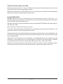
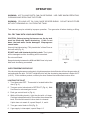
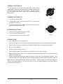
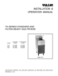
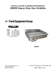
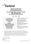
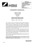
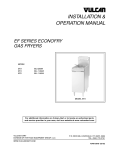
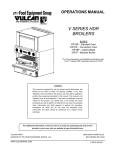
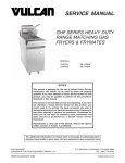
INSTALLATION &
OPERATION MANUAL
VGF-18 HEAVY DUTY
GAS FRYERS
MODEL
VGF-18
ML-136401
MODEL VGF-18
For additional information on Vulcan-Hart or to locate an authorized parts
and service provider in your area, visit our website at www.vulcanhart.com
VULCAN-HART
DIVISION OF ITW FOOD EQUIPMENT GROUP, LLC
P.O. BOX 696, LOUISVILLE, KY 40201-0696
TEL. (502) 778-2791
WWW.VULCANHART.COM
FORM 35638 (05-05)
IMPORTANT FOR YOUR SAFETY
THIS MANUAL HAS BEEN PREPARED FOR PERSONNEL QUALIFIED TO INSTALL
GAS EQUIPMENT, WHO SHOULD PERFORM THE INITIAL FIELD START-UP AND
ADJUSTMENTS OF THE EQUIPMENT COVERED BY THIS MANUAL.
POST IN A PROMINENT LOCATION THE INSTRUCTIONS TO BE FOLLOWED IN THE
EVENT THE SMELL OF GAS IS DETECTED. THIS INFORMATION CAN BE OBTAINED
FROM THE LOCAL GAS SUPPLIER.
IMPORTANT
IN THE EVENT A GAS ODOR IS DETECTED,
SHUT DOWN UNITS AT MAIN SHUTOFF VALVE
AND CONTACT THE LOCAL GAS COMPANY
OR GAS SUPPLIER FOR SERVICE.
FOR YOUR SAFETY
DO NOT STORE OR USE GASOLINE OR OTHER
FLAMMABLE VAPORS OR LIQUIDS IN THE
VICINITY OF THIS OR ANY OTHER APPLIANCE.
WARNING
IMPROPER INSTALLATION, ADJUSTMENT,
ALTERATION, SERVICE OR MAINTENANCE CAN
CAUSE PROPERTY DAMAGE, INJURY OR
DEATH. READ THE INSTALLATION, OPERATING
AND MAINTENANCE INSTRUCTIONS THOROUGHLY
BEFORE INSTALLING OR SERVICING THIS
EQUIPMENT.
IN THE EVENT OF A POWER FAILURE, DO NOT
ATTEMPT TO OPERATE THIS DEVICE.
© VULCAN-HART, 2005
—2—
INSTALLATION, OPERATION AND CARE OF
MODELS VGF-18 HEAVY DUTY GAS FRYERS
PLEASE KEEP THIS MANUAL FOR FUTURE USE
GENERAL
Your Vulcan-Hart Gas Fryer is produced with quality workmanship and material. Proper installation,
usage and maintenance will result in many years of satisfactory performance.
It is suggested that you thoroughly read this entire manual and carefully follow all of the instructions
provided.
OPTIONAL FIELD INSTALLABLE ACCESSORIES
Tank Brush
Grease Strip
4' (1.21 m) Quick Disconnect Hose
Tank Cover
(2) Twin Fry Baskets
(4) Casters
Single Basket
INSTALLATION
Before installing the fryer, verify that the type of gas (natural or propane) agrees with the
specifications on the fryer data plate which is located on the inside of the door. Also be sure the
fryer is built for the installation elevation.
The fryer must be restrained with adequate ties to prevent tipping when installed in order to avoid
the splashing of hot liquid.
UNPACKING
This fryer was carefully inspected before leaving the factory. The transportation company assumes
full responsibility for safe delivery upon acceptance of the shipment. Immediately after unpacking
the fryer, check for possible shipping damage. If the fryer is found to be damaged, save the
packaging material and contact the carrier within 15 days of delivery.
Do not use the door or its handle to lift or move the fryer.
ITEMS PACKAGED WITH FRYER
Crumb Screen
Basket Hanger
Warranty and Service Pack
Drain Pipe
(2) Twin Fry Baskets
(4) Legs
Manual
—3—
LOCATION
CAUTION: The equipment area must be kept free and clear of combustible substances.
Installation clearances:
Back:
Right Side:
Left Side:
COMBUSTIBLE
CONSTRUCTION
6" (152)
6" (152)
6" (152)
NONCOMBUSTIBLE
CONSTRUCTION
0"
0"
0"
The installation location must allow adequate clearances for servicing and proper operation. A
minimum front clearance of 35" (889 mm) is required.
There must be at least 16" (406.4 mm) clearance between the fryer and any open top flame units.
Adequate clearances for servicing and proper operation must be allowed.
Install the fryer in an area with sufficient air supply for combustion of the gas at the fryer burners.
Provide adequate clearance for air openings into the combustion chamber. Do not obstruct the flow
of combustion and ventilation air.
Do not permit fans to blow directly at the fryer. Wherever possible, avoid open windows next to the
sides or back of the fryer. Avoid wall-type fans which create air cross currents within the room.
INSTALLATION CODES AND STANDARDS
Your Vulcan Fryer must be installed in accordance with:
In the United States of America:
1. State and local codes.
2. National Fuel Gas Code, ANSI-Z223.1 (latest edition). Copies may be obtained from The
American Gas Association, Inc., 1515 Wilson Blvd., Arlington, VA 22209.
3. ANSI-NFPA Standard #96, Vapor Removal from Cooking Equipment, (latest edition), available
from the National Fire Protection Association, Batterymarch Park, Quincy, MA 02269.
In Canada:
1. Local codes.
2. CSA B149.1 Natural Gas and Propane Installation Code.
3. CSA C22.1 Canadian Electrical Code.
The above are available from the Canadian Standard Association, 5060 Spectrum Way, Suite 100,
Mississauga, Ontario, Canada L4W 5N6.
ASSEMBLY
Legs
Position fryer in an open space near the final installation area. Tilt fryer back, being careful to avoid
scratching the finish. Thread front legs clockwise into mounting plates provided on the bottom of
the fryer until seated. Tilt to front and thread back legs similarly. Carefully raise fryer to its normal
position and place it in the installing location.
—4—
Fryers Mounted on Optional Casters
Fryers mounted on casters must use a flexible
connector (NOT SUPPLIED BY VULCAN) that
complies with the Standard for Connectors of
Movable Gas Appliances, ANSI-Z21.69 • CSA6.16
and a quick-disconnect device that complies with
the Standard for Quick-Disconnect Devices for Use
With Gas Fuel, ANSI-Z21 • CSA 6.9.
In addition, adequate means must be provided to
limit the movement of the appliance without
depending on the connector and the quickdisconnect device or its associated piping to limit
the appliance movement. Attach the restraining
device to the rear of the fryer as shown in Fig. 1.
Fig. 1
If it is necessary to disconnect the restraint, turn off the gas supply before disconnection. Reconnect
the restraint before turning the gas supply on and returning the fryer to its installation position.
Instructions for installing casters to the fryer are included with the casters.
LEVELING THE FRYER
Stand Alone Installations
Once gas connections have been made, place a spirit level on top of the fryer. Adjust the legs to
ensure that the fryer is level front-to-back and side-to-side in the final installed position.
Battery Installations
When the fryer is part of a battery lineup, line the fryer up front-to-back and side-to-side with
adjacent battery equipment. Equipment front tops and manifold pipes must be aligned with adjacent
equipment. Once the fryer is in its exact location in the battery lineup, place a spirit level on top of
the fryer. Adjust the legs to ensure that the fryer is level front-to-back and side-to-side in the final
installed position.
—5—
GAS CONNECTIONS
CAUTION: All gas supply connections and any pipe joint compound used must be
resistant to the action of propane gases.
WARNING: PRIOR TO LIGHTING, CHECK ALL JOINTS IN THE GAS SUPPLY LINE FOR
LEAKS. USE SOAP AND WATER SOLUTION. DO NOT USE AN OPEN FLAME.
Rear Gas Connection for Stand Alone Installations
The gas inlet is located at the lower left rear.
Codes require that a gas shutoff valve be installed in the gas line ahead of the fryer.
The gas supply line must be at least the equivalent of 1/2" (12.7 mm) iron pipe. If using the optional
quick-disconnect flex hose, 3/4" (19 mm) iron pipe must be used unless 3/4" (19 mm) to 1/2" (12.7 mm)
reducing fittings are used. Make sure the pipes are clean and free of obstructions, dirt, and piping
compound.
After piping has been checked for leaks, all piping receiving gas should be fully purged to remove
air.
Front Gas Connection for Battery Installations
Codes require that a gas shutoff valve be installed in the gas line ahead of the fryer and battery of
equipment.
The gas manifold of a battery lineup of which the fryer is a part, must be installed using a regulator
design-certified by a nationally recognized testing lab to the applicable ANSI standard (regulators
available from Vulcan-Hart). The pressure regulator must have a maximum regulation capacity to
handle the total connected load and must have an adjustment range for manifold pressure marked
on the equipment rating plate(s). If the manifold pressure of the connected equipment is not the
same, a separate regulator must be supplied for all devices operating under different manifold
pressure ratings.
CONNECTION OF MANIFOLDS IN BATTERY
1. If the fryer requires alignment to match the battery lineup, loosen 2 bolts on each U bracket
securing the 11/4" (31.8 mm) manifold pipe to the fryer.
2. Shift the 11/4" (31.8 mm) manifold pipe left or right, in or out, until alignment with the equipment
battery manifold pipe is achieved. While holding the fryer manifold in place, tighten the holding
screws on the U bracket back in place.
3. Apply pipe sealer resistant to the action of propane gases around the threaded edge(s) of the
fryers 11/4" (31.8 mm) manifold pipe.
4. Engage the union nut on the fryer manifold pipe with the male fitting on the batteried unit
adjacent to the fryer. Draw up the union hand tight. Continue connecting the manifolds, following
these steps 1 - 4, until all units in the battery lineup are installed.
5. Using channel locks, tighten all connection points along the manifold of the entire equipment
battery.
6. Install manifold end cap if applicable.
7. Check all connection points along the manifold for gas leaks.
—6—
TESTING THE GAS SUPPLY SYSTEM
When test pressures exceed 1/2 psig (3.45 kPa), the fryer and its individual shutoff valve must be
disconnected from the gas supply piping system.
When test pressures are 1/2 psig (3.45 kPa) or less, the fryer must be isolated from the gas supply
system by closing its individual manual shutoff valve.
FLUE CONNECTIONS
DO NOT obstruct the flow of flue gases from the flue located at the rear of the fryer. It is
recommended that the flue gases be ventilated to the outside of the building through a ventilation
system installed by qualified personnel.
Adequate ventilation must be provided and must comply with NFPA Standard #96 (latest edition),
and with local codes.
Never make flue connections directly to the fryer.
The fryer must be located under a hood which has an adequate connection to an exhaust duct. The
hood must extend 6" (152.4 mm) beyond fryer sides.
Clearance above fryer should be adequate for products of combustion to be removed efficiently. An
18" (457 mm) minimum clearance should be maintained between the flue vent and the filters of the
hood venting system.
Information on the construction and installation of ventilating hoods may be obtained from the
standard for "Vapor Removal from Cooking Equipment," NFPA No. 96 (latest edition), available
from the National Fire Protection Association, Batterymarch Park, Quincy, MA 02269.
Adequate air should be provided in the kitchen to replace air taken out by the ventilating system.
This will prevent fryer function from being affected by a reduced atmospheric pressure.
—7—
OPERATION
WARNING: HOT OIL AND PARTS CAN CAUSE BURNS. USE CARE WHEN OPERATING,
CLEANING AND SERVICING THE FRYER.
WARNING: SPILLING HOT OIL CAN CAUSE SEVERE BURNS. DO NOT MOVE FRYER
WITHOUT DRAINING ALL OIL FROM THE TANK.
Tank warranty may be voided by improper operation. Turn gas valve off when draining or filling.
FILL FRY TANK WITH LIQUID SHORTENING
CAUTION: Before turning the burners on, the fry tank
must be filled with liquid shortening. If this is not
done, the tank walls can be damaged. Warpage can
cause leaks.
Use only liquid shortening. Fill fry tank to the "oil level" line on
the back wall (Fig. 2).
DO NOT melt solid shortening in the fry tank. The fry tank
will be damaged and the shortening will be scorched.
Do not overfill tank.
Keep shortening between the MIN and MAX lines in fry tank.
Add fresh shortening as needed.
Fig. 2
OVER TEMPERATURE DEVICE
If the shortening becomes overheated, a high temperature shutoff device will turn the gas valve off
and extinguish the pilot. DO NOT relight the pilot until the shortening temperature is below 300°F
(149°C). If this situation persists, contact your local Vulcan-Hart authorized service office.
LIGHTING THE PILOT
1. Turn thermostat OFF. Thermostat is located behind the
door (Fig. 3).
2. Turn gas control valve knob to OFF/PILOT (Fig. 4). Wait
5 minutes for unburned gas to vent.
3. Push gas control knob in (Fig. 4).
4. While still holding knob in, light the pilot with a lit taper.
Continue to depress knob for 30 seconds, then release the
knob. Pilot should remain lit when knob is released.
If pilot does not remain lit, repeat Steps 2, 3, and 4.
5. Turn gas control knob to ON (Fig. 5).
6. If gas supply is interrupted, repeat Steps 1-5.
—8—
Fig. 3
TURNING THE FRYER ON
To turn the fryer on, set the thermostat knob to the desired
temperature. After the set temperature has been reached, the
gas control shuts off gas flow to the burners. The pilot remains
lit. The burners will cycle on and off, maintaining the set
temperature.
TURNING THE FRYER OFF
1. Turn the thermostat OFF.
Fig. 4
2. Turn the gas control valve knob to PILOT. In this position
the pilot will remain lit.
3. To shut off all gas to the system, including the pilot, turn the
gas control valve knob to OFF.
EXTENDED SHUTDOWN
1. Turn the manual gas shutoff valve OFF.
2. Turn the thermostat knob OFF.
3. Turn the gas control valve knob to OFF.
Fig. 5
FRYING FOODS
• Heat shortening to set temperature.
•
Pieces of product to be fried should be about the same size to ensure the same doneness.
•
Drain or wipe dry raw or wet foods to minimize spatter when lowering into the hot oil.
•
Do not overfill baskets.
•
Carefully lower baskets into oil.
•
When frying doughnuts and fritters, turn product only once during frying.
•
When cooking French fries or onion rings, shake basket several times in a way that does not
spatter the shortening.
•
Batter-covered foods should be dropped carefully, one by one, into shortening or basket. If you
use the basket, first dip basket into the shortening to reduce batter build-up on basket surfaces.
When frying is completed, remove baskets or product. Hang baskets on rear basket hangers.
Remove food and season it. Do not salt food over the shortening because salt could cause a
chemical change in the oil.
—9—
SHORTENING LIFE
Shortening life may be extended by following these guidelines:
•
Do not salt foods over the fryer.
•
Use good quality shortening.
•
Filter shortening at least daily.
•
Replace shortening if it becomes poorly flavored.
•
Keep equipment and surroundings clean.
•
Set thermostats correctly.
•
Remove excess moisture and particles from food products before placing in fryer.
Add approximately 15% new oil daily. Keep level of shortening between the MIN and MAX level
on the fryer tank back wall. Add fresh shortening as needed.
DAILY FILTERING
Turn gas valve OFF when draining or filling.
The shortening should always be filtered while liquefied. A cold fryer will not drain properly because
the shortening under the cold zone tube area will remain hard, even if the heat is on for a few
minutes. If necessary, the clean-out rod may be used to carefully stir up hard fat to an area above
the cold zone where it will melt. After the cold zone is liquefied, turn the fryer thermostat and gas
valve OFF.
Shortening life will be extended by filtering at least once a day or more often if conditions warrant.
A commercial power filter (available from other manufacturers) may be used. Follow the
manufacturer's operating instructions for draining, straining, and replacing shortening in the fry
tank.
Another way to filter is to drain the shortening from the drain pipe through a filter bag, or cover the
receiving container with cheesecloth or other filtering material.
Filtering Procedure
1. Turn the fryer OFF.
2. Slowly remove the baskets, especially if shortening is hot, to prevent splashing.
3. Open the fryer door and attach the drain pipe to the drain valve.
4. Select a container of sufficient capacity and place it below the drain pipe.
5. If you are using a filter bag, tie it securely to the drain pipe. If other filter medium is used, place
it in the container.
6. Open the drain valve carefully so the oil stream is directed through the filter.
7. With a small amount of warm shortening, flush out scraps and sediment in the fry tank. Drain
the tank thoroughly and wipe clean.
8. If it is necessary to clean the tank more thoroughly follow the procedure shown in CLEANING
— WEEKLY OR AS REQUIRED.
9. Close the drain valve.
10. Pour the strained shortening back into the vat.
11. Add shortening to the "oil level" line.
— 10 —
CLEANING
Daily
Clean your fryer regularly. Keeping the fryer clean and free of accumulated grease will prevent
stubborn stains from forming. Wash all exterior surfaces at least once daily. Use a cloth with warm
water and a mild soap or detergent. Follow with a clear rinse, then dry.
If regular cleaning is neglected, grease will be burned on and discolorations may form. These may
be removed by washing with any detergent or soap and water. A self-soaping scouring pad may
be used for particularly stubborn discolorations.
Always rub with the "GRAIN" in a horizontal direction. Do not use stainless steel wool pads on
stainless steel finishes. Pieces of the steel wool will adhere to the stainless steel surface and cause
rusting.
Weekly or as Required
1. Once the shortening has been drained, flush out scraps and sediment with a small amount of
warm shortening. Allow the tank to drain thoroughly.
2. Close the drain valve and fill the tank with a non-corrosive, grease-dissolving commercial
cleaner, following the manufacturer's instructions.
3. Set the thermostat at a temperature recommended by the manufacturer of the commercial
cleaner and boil the solution for 15 to 20 minutes. Monitor boiling to prevent overflow.
4. Drain the cleaning solution from the tank.
5. Close the drain valve and refill the tank with water. Add 1 cup (237 ml) of vinegar to neutralize
alkaline left by the cleaner. Bring the solution to a boil and allow it to stand for a few minutes.
6. Drain the tank and rinse thoroughly with clear, hot water. All traces of cleaner must be removed.
Dry the tank thoroughly.
7. Close the drain valve.
8. Add shortening between the MIN and MAX level lines.
Cleaning Stainless Steel
Stainless steel may be cleaned with ordinary soap or detergent and water. To prevent water spots
and streaks, rinse equipment thoroughly with warm water and wipe dry with a soft clean cloth. The
addition of a rinsing agent will also help prevent spotting.
Fingerprints
Fingerprints are sometimes a problem on highly polished surfaces of stainless steel. They can be
minimized by applying a cleaner that will leave a thin, oily or waxy film. Wipe cleaner on and remove
excess with a soft dry cloth.
— 11 —
MAINTENANCE
WARNING: HOT OIL AND PARTS CAN CAUSE BURNS. USE CARE WHEN OPERATING,
CLEANING AND SERVICING THE FRYER.
WARNING: SPILLING HOT OIL CAN CAUSE SEVERE BURNS. DO NOT MOVE FRYER
WITHOUT DRAINING ALL OIL FROM THE TANK.
FLUE
Annually check the flue when it is cool to be sure it is free of obstructions.
SERVICE AND PARTS INFORMATION
To obtain service and parts information, contact the Vulcan-Hart Service Agency in your area (refer to
our website, www.vulcanhart.com for a complete listing of Authorized Service and Parts depots.
When calling for service, the following information must be available: Model number, serial number,
manufacture date (MD), gas type and voltage.
FORM 35638 (05-05)
— 12 —
PRINTED IN U.S.A.