1
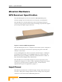
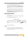
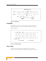
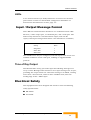
GPS Timing Receiver for eMGW/MGW System Installation and Operation Manual February 2005 Alvarion P/N 214028 Symmetricom P/N 197-03850-02, Issue 1 Error! No text of specified style in document. GPS Timing Receiver Installation and Operation Manual ii About this Guide Chapter 1 – System Description. This chapter gives an introduction to the GPS Receiver and describes the command channel and control-display-unit ports and the Alvarion hardware. Chapter 2 – Installation. This chapter describes how to install the GPS Receiver and position location. Chapter 3 – Operations. This chapter describes the system indicators and command channel operation. Appendix A –Technical Data. Appendix B – EMC Emissions and Immunity. Appendix C – Maintenance. Appendix D – The Global Positioning System (GPS). Appendix E – Glossary. Contents Chapter 1 - System Description...............................................................1-1 Introduction ........................................................................................... 1-2 Command Channel and Control-Display-Unit (CDU) Ports ........................ 1-3 Alvarion Hardware .................................................................................. 1-4 GPS Receiver : Specification ......................................................................... 1-4 Input Power.................................................................................................. 1-4 Output Specification .................................................................................... 1-5 1PPS ......................................................................................................... 1-5 2.048 MHz................................................................................................. 1-6 Time of Day ............................................................................................... 1-6 LEDs ......................................................................................................... 1-7 Input / Output Message Format................................................................... 1-7 Time of Day Output ................................................................................... 1-7 Electrical Safety ........................................................................................... 1-7 Chapter 2 - Installation .............................................................................2-1 Installation............................................................................................. 2-2 Antenna Mounting ....................................................................................... 2-2 Lightning Protection Considerations ............................................................. 2-4 Protection Against Lightning......................................................................... 2-6 At the Antenna .......................................................................................... 2-6 At the GPS Receiver Unit ........................................................................... 2-8 The Lightning Arrestor ............................................................................... 2-10 Detailed Installation procedure................................................................... 2-11 Installing the Surge Protection................................................................. 2-11 Connecting the N-type to TNC adaptor .................................................... 2-11 Connecting the Grounding Cable............................................................. 2-12 Connecting the “Equipment” side ............................................................ 2-12 Connecting the Surge side ....................................................................... 2-14 Connection Diagram................................................................................ 2-15 Mounting the GPS Receiver ........................................................................ 2-16 Mounting in Equipment Cabinets ............................................................ 2-16 Contents Cable and Power Connections.....................................................................2-17 Casing Ground Connection ......................................................................2-17 Antenna Connection ................................................................................2-18 Output (Timing/Frequency) Connection ...................................................2-18 Command Channel to Alvarion eMGW/MGW System...............................2-18 CDU-PC Connection.................................................................................2-19 Time of Day Connection ...........................................................................2-20 Ground Topography .................................................................................2-20 Power Connection ....................................................................................2-20 Position Location.................................................................................. 2-22 Automatic Position Location........................................................................2-22 User Entered Position .................................................................................2-23 Chapter 3 - Operations ............................................................................ 3-1 Operation ............................................................................................... 3-2 Indicators .....................................................................................................3-2 Command Channel Operation.......................................................................3-3 Appendix A - Technical Data Symmetricom™GPS Receiver................A-1 Performance Characteristics .........................................................................A-1 1PPS Output:.............................................................................................A-2 2.048 MHz Output: ....................................................................................A-2 Timing Receiver Connectors: .........................................................................A-2 Indicators: ....................................................................................................A-3 Environmental Conditions: ...........................................................................A-3 GPS Receiver..............................................................................................A-3 Antenna.....................................................................................................A-3 Electromagnetic Compatibility ...................................................................A-3 Safety ........................................................................................................A-4 Appendix B - EMC Emissions and Immunity.........................................B-1 FCC Class B Notice...................................................................................... B-1 Appendix C - Maintenance ......................................................................C-1 Appendix D - The Global Positioning System (GPS) ............................D-1 Precise Timing ............................................................................................. D-2 GPS Receiver Positioning and Navigation ..................................................... D-2 Standard Positioning Service (SPS) .............................................................. D-3 Precise Positioning Service (PPS) .................................................................. D-5 Geodetic Datums ......................................................................................... D-5 Appendix E - Glossary............................................................................. E-1 GPS Timing Receiver Installation and Operation Manual ii Figures Figure 1-1: Alvarion GPS Timing Receiver ........................................................ 1-4 Figure 1-2: Output Connections ...................................................................... 1-5 Figure 1-3: 1PPS Pulse .................................................................................... 1-6 Figure 1-4: 2.048 MHz Signal .......................................................................... 1-6 Figure 2-1: Alvarion GPS Timing Receiver - Back ............................................. 2-2 Figure 2-2: Typical Antenna Mounting............................................................. 2-3 Figure 2-3: Typical Antenna Lightning Arrestor ............................................... 2-7 Figure 2-4: Example of Connections ................................................................ 2-9 Figure 2-5: Lightening Arrestor...................................................................... 2-10 Figure 2-6: Installation of Lightening Arrestor on Mast .................................. 2-11 Figure 2-7: Connecting the TNC to N-type Adaptor ........................................ 2-12 Figure 2-8: Connecting the RF TNC-type side to the “Equipment” side........... 2-13 Figure 2-9: Connecting the Coax Cable to the Surge Side .............................. 2-14 Figure 2-10: Lightening Protector Connection Diagram.................................. 2-15 Figure 2-11: Typical Mounting in Cabinet...................................................... 2-16 Figure 2-12: Cable Connections..................................................................... 2-17 Figure 2-13: Female Power Connector (cable end view) ................................. 2-21 Tables Table 2-1: J7 Pin Connection......................................................................... 2-19 Table 2-2: J8 Pin Connections ....................................................................... 2-20 Table 2-3: J21 Pin Connections ..................................................................... 2-21 Table 3-1: LED Display.................................................................................... 3-3 1 Chapter 1 - System Description In this Chapter Introduction, page 1-2 Command Channel and Control-Display-Unit (CDU) Ports, page 1-3 Alvarion Hardware, page 1-4 Chapter 1 - System Description Introduction Optimized for the Alvarion eMGW/MGW System, the GPS Receiver is a complete, stand-alone, Global Positioning System (GPS) Time and Frequency generator. It has been designed to provide a stable signal source which possesses the long-term stability of a cesium clock, but at a fraction of the cost. This equipment provides an accurate Primary Reference Source (PRS) for applications requiring absolute timing/frequency accuracy. Developed with flexibility in mind, the GPS Receiver delivers precise measurement and control of both Time and Frequency for synchronizing the Alvarion eMGW/MGW System anywhere in the world, without the need for calibration. The GPS Receiver comprises a GPS receiver integrated with a stable OCXO oscillator, within a unit designed for mounting in a standard 19 inch telecommunications rack system. A 50 meter coaxial cable connects an active antenna to the GPS receiver. The GPS Receiver Timing Receiver contains a GPS receiver, power supply module, oscillator, and the basic output connections. LEDs on the front panel display status information. If the satellite signal is interrupted, the GPS Receiver enters a holdover mode which typically maintains frequency to better than ±5x10⁻¹⁰ per day. When the GPS signal is restored, the GPS Receiver automatically reverts to normal operation mode. The GPS Receiver is designed for automatic operation without the need for user intervention. It can however, be accessed via a serial port for configuration and debug purposes. NOTE It is essential to adhere to the specified power supply rating if serious damage to the GPS Receiver is to be avoided. GPS Timing Receiver Installation and Operation Manual 1-2 Command Channel and Control-Display-Unit (CDU) Ports Command Channel and ControlDisplay-Unit (CDU) Ports The Command Channel rear panel port enables any commercially available PC (running Windows 95/98/NT/2000/XP and a terminal display program) to initialize, customize, and control the unit. In addition, the Control-Display-Unit (CDU) port connected to a PC and using commercially available software allows the operator to interrogate and display the many available parameters for tracking, and timing applications. It should be noted that it is not always necessary to have a PC connected and running the software since the unit will retain all settings, output selections, and almanacs in its internal memory. These are ready to function at the next switch on, without further operator intervention. GPS Timing Receiver Installation and Operation Manual 1-3 Chapter 1 - System Description Alvarion Hardware GPS Receiver: Specification The GPS Timing Receiver for the Alvarion eMGW/MGW System, includes fittings and attachments for the majority of installations. The GPS Receiver includes Motorola™ M12 technology forming its receiver section, plus the latest in PLD technology to provide the signal processing and digital support features. Figure 1-1: Alvarion GPS Timing Receiver The GPS Timing Receiver is a complete stand-alone system, designed to operate in an internal environment requiring only power and GPS antenna connections. On the Timing Receiver, there is one R.F. antenna input, a 1PPS port providing precise timing, one 2.048MHz frequency output, plus two RS232 serial ports providing command/control functions. A Time of Day channel also supplies time information. The GPS Receiver is thermally designed to ensure operation in the temperature range 0°C to +60°C, with a maximum temperature shock rate of 10°C per hour when in holdover mode. A full technical specification is given in Appendix A, page A-1. Input Power The GPS is operated from a nominal supply voltage of 48 volts DC (3672 volts). This power rating is printed on the casing, above the power connector on the back of the GPS Timing Receiver. GPS Timing Receiver Installation and Operation Manual 1-4 Alvarion Hardware The positive and negative supply leads may be left floating or either one may be connected to Ground (encompassing the -48V telecommunications standard). We do not recommend connecting the positive or the negative supply leads to ground. A safety ground must be connected to the external case using the terminal provided (see Figure 1-2). An externally accessible fuse is provided on the rear panel. Normally, field replacement of the fuse is neither required nor recommended. Replace only with same type and rating, 250V, 2A, Time Lag. The integrity of the GPS Receiver cannot be guaranteed if operated outside design specification limits. The rise and fall times of the power supply should be less than 1 second. Output Specification The following sections describe the individual outputs with illustrations of the pulse shapes. For a description of the individual PIN connections, see the.Cable and Power Connections section from page 2-17. Command Unit: rear panel POWER ANTENNA GPS TIME & FREQUENCY RECEIVER 1PPS 2.048MHz COMMAND CHANNEL TIME OF DAY CHANNEL FUSE 2A -48V POWER LED Figure 1-2: Output Connections 1PPS This output (locked in phase with the 2.048MHz frequency output) represents the 1 second pulse transmitted from the GPS satellites, aligned to GPS time. All signals are square waves with TTL compatible levels when driving a 50Ω load. GPS Timing Receiver Installation and Operation Manual 1-5 2A Chapter 1 - System Description 1PPS Pulse Format 2.048 MHz 1PPS Pulse 488ns 1 second New second mark New second mark Figure 1-3: 1PPS Pulse 2.048 MHz This signal may be used as a synchronization interface. The pulse is a continuous DC biased square wave with TTL compatible levels when driving a 50Ω load. V OH V OL 488ns V OH ≥ 2.4 Volts V OL ≤ 0.8 Volts Figure 1-4: 2.048 MHz Signal Time of Day This communication port utilizes an RS232 9-pin ‘D’ type female connector. A full description of the output message is given on page 1-7. GPS Timing Receiver Installation and Operation Manual 1-6 Alvarion Hardware LEDs A set of three function (or mode) indicators are located on the front panel. These consist of colored LEDs configured to illuminate as described in the Indicators section, page 3-2. Input / Output Message Format Three RS-232 communication interfaces are available from the GPS Receiver, a time output port, a Command port, and a CDU port. The Time of Day channel is a uni-directional output, with the PC report/control port being bi-directional. The defaults are as follows; Baud Rate Parity Stop Bits Start bits Data bits 9600 None 1 1 8 The GPS Receiver may be configured, and will report both status and satellite conditions via the CDU port, utilizing an upgraded TSIP protocol. Time of Day Output The RS-232 Time of Day port will output the following message once every second. Messages will continue to be output during a loss of sync, providing the output clocks are valid. The message is in ASCII, starting more than 1 microsecond, and less than 5 milliseconds, from the leading edge of the 1 PPS output. Electrical Safety This equipment has been designed and tested to meet the following safety specifications: EN 60950 UL 60950 GPS Timing Receiver Installation and Operation Manual 1-7 2 Chapter 2 - Installation In this Chapter: Installation, page 2-2 Position Location, page 2-22 Chapter 2 - Installation Installation Installing a basic system will require the following: Mounting of the antenna and the 2 lightning arrestors Connecting a power supply to the GPS Receiver Interconnecting the antenna, the 2 lightning arrestors, the GPS Receiver, and a PC. Connecting the Command Channel and CDU ports to a PC. Installing the TSIP compatible Software to the PC. Figure 2-1: Alvarion GPS Timing Receiver - Back Antenna Mounting The antenna supplied is of the active type, and is suitable for almost all applications. It is supplied with a pre-attached, 1-meter RG58 cable, terminated with a male TNC connector. Before commencing installation, check that all the items detailed in the contents list have been supplied. The antenna is supplied with two O-type mounting clamps for attachment to a mounting pole. Figure 2-2 shows an example of how this might be achieved. When mounting the antenna, ensure the antenna has a clear view of the horizon and is at least 2 meters away from transmission sources which may interfere with reception. Avoid the direct path of any microwave links. Using the C-MAP software and the GTU check that the S/N ratio is at least 33.dB and that at least 4 satellites are in view with this minimum S/N signal. If you do not get these results check another antenna position. GPS Timing Receiver Installation and Operation Manual 2-2 Installation Figure 2-2: Typical Antenna Mounting CAUTION DO NOT allow the pole or other surfaces to extend higher than the underside of the antenna. Such a condition would impair signal reception. The most important consideration in selecting a position for the antenna is the presence of objects which obscure the sky or horizon. Where possible, there should be no obstruction to a full view of the sky. Overhead wires and other very narrow obstructions may be considered as invisible to the signals, provided that they are a few meters away. Large flat surfaces can decrease performance of the receiver. GPS Timing Receiver Installation and Operation Manual 2-3 Chapter 2 - Installation Be especially wary about mounting the antenna directly onto the fascia of a flat roof. To overcome this situation, elevate the pole about 1 meter above the flat surface. A satellite prediction program may usefully be employed to check a potential installation, and also to identify directions in which obstructions may be a particular source of problems. The antenna is connected to the GPS Receiver by a coaxial cable fitted with TNC connectors at each end. Where possible, avoid exposing the cable and connectors to weather and other environmental conditions. To install the antenna: 1. Insert the antenna cable through the bracket and the tightening pipe. 2. Fasten the tightening pipe to antenna. 3. Insert 2 U bolts through the mounting pole and connect to the bracket. 4. Insert flat Washers & Spring Washers & Nuts and close. NOTE Except for very temporary periods, it is desirable that the antenna TNC connector should be protected from the effects of weather. When connecting the cable to the antenna, a smear of silicone grease (not supplied) will provide added protection. The connector supplied is designed to be weather proof. It should not be altered or refitted to another cable. Otherwise, the connection may not be fully protected from a hostile environment, leading to operational problems. When the GPS Receiver is operational, the antenna assembly may be disconnected for short periods (e.g. maintenance or repair) without interruption to the unit outputs. Lightning Protection Considerations As the antenna is roof mounted (to have a clear view of the sky) it is likely to be exposed to lightning strikes. Protection against this is afforded by ensuring adequate grounding of the mountings as described below. GPS Timing Receiver Installation and Operation Manual 2-4 Installation There is no way to provide 100% protection for electronic equipment from direct strike damage. It is possible however, to reduce the likelihood of damage from near strike induced fields by ensuring the installation obeys some fundamental rules. Lightning arrestors are not 100% efficient, a residual attenuated electrical pulse being transmitted down the antenna cable, may still contain sufficient energy to damage equipment within the building. Therefore, a second lightning arrestor is required at the equipment end of the cable, preferably where the antenna cable enters the building. Basic Considerations:ENSURING THE MOUNTING BRACKET IS PROPERLY GROUNDED. This must be achieved by employing a certified, low impedance connection (a broad, flat lightning conductor strap of sufficient thickness to provide adequate mechanical durability) able to carry the thousands of amperes which may flow. Attaching the antenna mounting clamp onto a pole which is correctly grounded is the recommended method. The second lightning arrestor should be mounted where the antenna cable enters the building and properly grounded to earth termination. Implementation In order to divert the lightening currents induced in the coax cable, from entering the facilities, we recommend the use of Andrew grounding kit (not supplied), to connect the shield of the coax to earth termination. The recommended Andrew grounding kit (not supplied) definition is: Type 223158 or equivalent. Installation instructions are included in the grounding kit. GPS Antenna - Installation Restriction Case 1 In case that the GPS antenna is installed on location that can expose it to direct lightning hit. The installer should use a special accessories set (see Andrew grounding kit) to ground the coax shield to the "Grounding Plate" which should be located near the Cables Entrance of the shelter (this instruction is additional to the regular protection that is recommended to be used) GPS Timing Receiver Installation and Operation Manual 2-5 Chapter 2 - Installation Case 2 In case that the GPS antenna is not exposed to direct lightning hit it is recommended to use the regular protection set on the antenna side and at the indoor side. Minimize the exposure of the antenna cable to electrically induced fields. This is easily achieved by feeding the cable down the center of the pole used to mount the bracket. Ensure all conduits exposed to induced fields are of heavy gauge, welded seam construction, and are properly grounded. NEVER work on any part of the installation or cabling when there are weather conditions that may result in lightning strikes or corona discharge. Protection against Lightning During installation, it is essential to include a method of affording protection from the effects of a lightning strike. The example described in the following text enables a reasonable amount of predictability to the outcome of a strike. Without such provision, the discharge current will flow directly through the GPS Receiver installation, usually destructively. CAUTION This provision of a low impedance path is mandatory. In addition, it is imperative that the building is fitted with a suitable lightning conductor & lightning rod. At the Antenna A proprietary Lightning Arrestor should be installed, of a type which does not reduce GPS signal transfer. Install the lightning arrestor near to the antenna (e.g. on the mounting pole), ensuring all connections maintain electrical and environmental protection. The GPS Receiver and other equipment in the receiver rack should be protected from lightning using two co-axial gas discharge tube protectors which should be connected close to the top of the antenna tower and at the input bulkhead respectively. It is also desirable to route the coaxial cable inside the pole if possible, or alternatively, secure the coaxial cable securely to the pole. Avoid sharp bends or angles in the routing of both the cable and the main grounding connection. GPS Timing Receiver Installation and Operation Manual 2-6 Installation Having thereby passed a large proportion of the lightning discharge current to earth, it is then necessary to make provision to deal with the lesser current flows. Figure 2-3: Typical Antenna Lightning Arrestor GPS Timing Receiver Installation and Operation Manual 2-7 Chapter 2 - Installation At the GPS Receiver Unit After taking the precautions described previously in the antenna installation, it should be understood that a destructive residual current may still be present in the cable coming down from the antenna to the GPS Receiver unit. A second lightning arrestor must be installed near to the GPS Receiver to further dissipate any remaining lightning energy. Where there is no access to the metal framework of the building, it is absolutely imperative to erect a suitable lightning conductor. Failure to do so is almost certain to result in destruction of the GPS Receiver in the event of the antenna receiving a near lightning strike. There are additional benefits when the GPS Receiver is mounted in a telecommunications equipment cabinet. Such cabinets provide an environment which affords additional protection when correctly connected to the central earthing system of the building (main bus). This earthing system may thereby prevent current flow between equipment and cabinets. When making the connection of the cabinet to the central earthing system, ordinary round cable (of any diameter) is not an acceptable choice and should be avoided. The preferred choice is a flat metallic tape or ribbon of substantial width, but with a small thickness. A width of 8cm (3 inch) is suggested, with a thickness of 1.5mm (1/16 inch). Any compromise upon these recommended dimensions may diminish the lightning protection. Avoid sharp changes in direction when placing the conductor. At the earth end use multiple connection points if at all possible. All connections should incorporate as large an area of contact as possible. This may be achieved by using large bolts, and washers of substantial diameter. A single earth stake of only about 0.7meters (2 feet) length is insufficient, offering no real protection at all. The rod should penetrate deep enough to reach permanently dampened earth or rock. Even then, two such rods would offer significantly greater protection. All connections should incorporate as large an area of contact as possible, which is made more probable by the use of large bolts, and substantial washers. GPS Timing Receiver Installation and Operation Manual 2-8 Installation Figure 2-4: Example of Connections GPS Timing Receiver Installation and Operation Manual 2-9 Chapter 2 - Installation The Lightning Arrestor The lightening arrestor kit contains 5 parts: 1. The Lightning Arrestor quantity 2. 2. Grounding cable. 3. 1 meter coax cable. 4. Bracket for mounting the lightning arrestor on the mast - see Figure 2-3. 5. N type to TNC Adaptor. – optional depending on lightning arrestor connector type. The lightning arrestor will be delivered in one of the following options with TNC connectors or with N-Type connectors (as given in the picture below). Figure 2-5: Lightening Arrestor CAUTION DO NOT USE THE GPS RECEIVER WITHOUT LIGHTNING PROTECTION INSTALLED GPS Timing Receiver Installation and Operation Manual 2-10 Installation Detailed Installation procedure Installing the Surge Protection Install the lightning arrestor on the mast as shown in Figure 2-3. Install the Surge Protector device and the grounding cable on the backside of the rack – as shown below. Tighten well using M8 screw. Figure 2-6: Installation of Lightening Arrestor on Mast Connecting the N-type to TNC adaptor Connect the TNC to N-type adaptor (part of the kit) on the “surge” side – if the lightning arrestor has N-type connectors. If not the cable should be connected directly without any adaptor. GPS Timing Receiver Installation and Operation Manual 2-11 Chapter 2 - Installation Figure 2-7: Connecting the TNC to N-type Adaptor Connecting the Grounding Cable Connect the other side of the grounding cable to a grounding source of the rack. NOTE A good ground system is required for proper installation and operation. The lightning arrestor is only as good at suppressing impulses as the electrical ground system that is connected to the unit. Connecting the “Equipment” side Connect the 1 meter RF TNC-type side (cable from the kit) to the Protector device – to the “Equipment” side (if the lightning arrestor has N-type connectors use the N-type to TNC adaptor). GPS Timing Receiver Installation and Operation Manual 2-12 Installation Figure 2-8: Connecting the RF TNC-type side to the “Equipment” side GPS Timing Receiver Installation and Operation Manual 2-13 Chapter 2 - Installation Connecting the Surge side Connect the 50m coax cable from antenna to the Lightning Arrestor device – to the Surge side (if the lightning arrestor has N-type connectors use the TNC to N-type adaptor as described in Figure 2-9). Figure 2-9: Connecting the Coax Cable to the Surge Side GPS Timing Receiver Installation and Operation Manual 2-14 Installation Connection Diagram 19 inch Rack RF cable L=1m To TNC RF connector (rear) GPS Receiver Ring lug Mounting screw PROTECTOR DGXZ+15TFTF-A RF cable To GPS antenna Ground cable AWG8 L=3m Ground Bus Figure 2-10: Lightening Protector Connection Diagram GPS Timing Receiver Installation and Operation Manual 2-15 Chapter 2 - Installation Mounting the GPS Receiver The GPS Timing Receiver is designed for integral mounting within a standard 19 inch telecommunications equipment cabinet. Mounting in Equipment Cabinets Two integral mounting flanges are provided on the ends of the front panel of the unit. All cable connections are made at the rear of the Timing Receiver. Refer to Figure 2-11. Figure 2-11: Typical Mounting in Cabinet It will not normally be necessary to install any cooling fans into the cabinet containing the GPS Receiver. However, refer to the Technical Specifications where installations are to be subjected to high ambient temperatures. GPS Timing Receiver Installation and Operation Manual 2-16 Installation Cable and Power Connections Electrical installation must only be carried out by suitably qualified personnel. Particular attention should be given to protecting the site from the damaging effects of lightning strikes (refer to the section on Protection against Lightning on page 2-6). The GPS Receiver requires a minimum of four connections to be made: Chassis Earth Antenna Output (Timing/Frequency) Power Power supply voltage is to be a nominal 48Volts DC. Before commencing electrical connection, reference should also be made to the technical data (see Appendix 1). Power supplies and returns cables should be secured to avoid accidental damage, and isolated from the chassis at all times. Ensure compatibility of power supply with the GPS Receiver being installed. The integrity of the GPS Receiver cannot be guaranteed if operated outside specified design limits. Command Unit: rear panel POWER ANTENNA GPS TIME & FREQUENCY RECEIVER 1PPS 2.048MHz COMMAND CHANNEL TIME OF DAY CHANNEL FUSE 2A -48V POWER LED Figure 2-12: Cable Connections Casing Ground Connection The GPS Receiver is grounded (earthed) through a threaded stud which is provided on the rear of the casing. Alternatively, this may be repositioned to utilize one of the unused threaded insets (on the side of the GPS Receiver casing), intended for the fitting of alternative mounting flanges. GPS Timing Receiver Installation and Operation Manual 2-17 2A Chapter 2 - Installation CAUTION Ensure the casing ground connection is the FIRST connection made to the unit, and the LAST to be disconnected. Interference problems will be minimized by effective and direct ground connections. A screened data cable should be used and grounded at the GPS Receiver connector end. When fitting the host connector, it is desirable to connect both the screen and drain wires to a connector having 360° connectivity (no tails). Any other solution degrades the EMC performance. For details of power supply grounding, see Power Connection, page 2-20. Antenna Connection After mounting the antenna (page 2-2), route the cable to the connection on the GPS Receiver marked ‘ANTENNA’. Use the cable as supplied by Alvarion , do not lengthen the antenna cable as this may have an adverse effect on signal attenuation and overall system performance. The cable as supplied also provides correct RF screening, and protection from pulses inducted on the antenna cable by lightning strikes. Output (Timing/Frequency) Connection The GPS Receiver makes a number of different outputs available for user selection. Referring to Figure 2-12, these connectors are as follows:J3 1PPS = 1 pulse per second 488ns wide pulse – active low J4 2.048MHz = square wave Command Channel to Alvarion eMGW/MGW System The Command Channel Port is of a bi-directional RS232D type for control and data interchange. Use the cable provided with the Alvarion eMGW/MGW System to connect this port. The cable has one 9-pin male connector to mate with the Command port of the GPS Receiver, the other end has a 9-pin male connectors to mate with the CMD port of the Alvarion eMGW/MGW System. GPS Timing Receiver Installation and Operation Manual 2-18 Installation Table 2-1: J7 Pin Connection J 7 Connector PIN Connection, Function = Command Channel (as viewed at the GPS Receiver connector) Pin 1 not connected Pin 2 TX - CMD Pin 3 RX - CMD Pin 4 DTR - CMD Pin 5 Ground Pin 6 DSR - CMD Pin 7 TX - CDU Pin 8 RX - CDU Pin 9 Ground CDU-PC Connection These messages are of binary format. Users are unable to use a terminal emulator program to control the GPS Receiver unit through the CDU port. Special software supporting the TSIP protocol must be used for this purpose. When operating the GPS Receiver from a PC based Control-Display-Unit using TSIP software, the cable link should be made with the RS232 ports, i.e. PC COM port to the GPS Receiver Command Channel port. A special ’Y’ cable is required (NOT SUPPLIED) to connect both the Command Channel and CDU ports simultaneously. GPS Timing Receiver Installation and Operation Manual 2-19 Chapter 2 - Installation Time of Day Connection The Time of Day port outputs a message once every second. This output is NOT user configurable. Table 2-2: J8 Pin Connections J 8 Connector PIN Connection, Function = Time of Day (as viewed at the GPS connector) Pin 1 Not used Pin 2 TX data Pin 3 RX data Pin 4 DTR Pin 5 Ground Pin 6 DSR Pin 7 not used Pin 8 not used Pin 9 not used Use the cable provided with the Alvarion eMGW/MGW System for connection to the ‘TOD’ port. The port configuration is described in the Input / Output Message Format section, page 1-7. Ground Topography The power supply input is floating. Voltage inputs should be left floating with reference to ground Earth ground MUST be connected to the external case with a screw fitting (refer to Casing Ground Connection, page 2-17). Power Connection The appropriate power cable for the 3.4.8 Power Connection unit is supplied with the system. During manufacture, this cable is fitted with a Binder connector (4-pin female) matching the ‘POWER’ connection of the GPS Receiver. Details of the input voltage and relevant connections are given below: 48Volt nominal (36 to 72V) DC = 4-pin Binder input connector GPS Timing Receiver Installation and Operation Manual 2-20 Installation Table 2-3: J21 Pin Connections J 21 Connector 4-PIN Connector, Function = Power Cable Core color (viewed at the GPS Receiver connector) Pin 1 Not Connected N/A Pin 2 GND White Pin 3 Supply + Red Pin 4 Supply - Black For use on a negative supply connect ‘supply +’ to ground. For use on a positive supply connect ‘supply -‘ to ground. Figure 2-13: Female Power Connector (cable end view) The maximum power dissipated, at warm-up, does not exceed 20Watts. Power connection wiring should be as short as is practicable, and not shared with heavy current or intermittent devices such as motors, starters, etc. GPS Timing Receiver Installation and Operation Manual 2-21 Chapter 2 - Installation Position Location When extracting data from the Global Positioning System, there are four unknown variables which the GPS receiver must resolve: X position, Y position, Z position, and time. Each of these variables has an effect on the other. Therefore, before the GPS Receiver can produce an accurate time output, it must first obtain valid data for the other three values. Automatic Position Location When the system is installed and powered for the first time, the GPS Receiver will automatically proceed to obtain an accurate position fix (unless it receives instructions to the contrary). The position fix is performed with the knowledge that there is no user motion. When the position is established, the solution is frozen in positional terms and all measurements are diverted to time and frequency states. Automatic sequence:Search the sky to lock-on to satellites, and download almanac data for all other remaining satellites. Calculate a position, and perform checks to ensure the solution is accurate. Change the frequency of the oscillator so that it matches the timing information received from the GPS satellites. If position matches, enter time transfer mode with stored position. If position does not match, enter averaging mode. When the timing and frequency outputs are within specification, enable the outputs, illuminate the Green LED. Average the position data when an accurate position is determined, Store this surveyed position in memory for future use. This automatically derived position will be of sufficient accuracy to enable output of a timing solution. Calculated position being within the specifications of the GPS Receiver system, and of an accuracy superior to most maps. NOTE Should the installation subsequently suffer an interruption to the power supply, the Alvarion-GPS Receiver re-initializes itself utilizing the Surveyed Position . GPS Timing Receiver Installation and Operation Manual 2-22 Position Location User Entered Position In an attempt to expedite the surveying process, the GPS Receiver may be given a position (e.g. entered manually). This user entered position is used to determine which satellites are currently in view. This can only occur when the GPS Receiver has acquired its first satellite, the date and time can then be determined. Utilizing a user entered position (and stored almanacs of the satellites), the satellites in view can be calculated. CAUTION The accuracy of this user entered position must be to within 50m (or better) otherwise, the GPS Receiver will reject the value and use its Computed Average Position value. When in doubt, use the Survey Average. GPS Timing Receiver Installation and Operation Manual 2-23 3 Chapter 3 - Operations In this Chapter Operation, page 3-2 Indicators, page 3-2 Command Channel Operation, page 3-3 Appendix A - Technical Data Symmetricom(PPGPS Receiver Operation The installation of the system is described in detail in Chapter 2 - of this manual. A minimum requirement for operation of the GPS Receiver being the connection of the antenna, the lightning arrestors plus the grounding and power cables. Once powered, the GPS Receiver will automatically start to work and commence the Position Location sequence described on page 2-22. Due to the need to warm up the oscillator, the equipment will need a warm-up period of approximately 6 minutes (Red flashing). When the oscillator has warmed up, the green LED starts to flash. Once frequency is within specification, the Green LED will be permanently illuminated. LED Indication Mode Red (flashing) Warm-up Green (flashing) GPS but no-sync Green (steady) Normal Operation The GPS Receiver will retain its configuration and last position fix in memory when powered down, so that when switched on again, it will recommence working without further intervention. Indicators A set of three function (or mode) indicators is located on the front panel. These consist of colored LEDs configured to illuminate as follows: RED (flashing) RED Warm-up mode. Alarm indicates failed self-test, or timing out of specification. YELLOW No GPS - Holdover Mode indicates that the oscillator is not synchronized to the GPS satellites. GREEN (flashing) GPS - no sync. frequency outputs NOT synchronized. GREEN Oscillator lock indicates that the oscillator is locked to the GPS satellites frequency. GPS Timing Receiver Installation and Operation Manual 3-2 Operation Table 3-1: LED Display Conditions Yellow (no GPS) Green (Osc. On) Red Alarm Warm-up mode (~ 6 minutes from switch-on) Off Off Flash After warm up – outputs but not valid (Stabilization) Off Flash Off Normal operating mode Off On Off On Off Off Recovery from Flywheeling (stabilization) Off Flash Off GPS Receiver failed self test Off Off On Firmware Update Download Process Flash Flash Off No power Off Off Off Flywheeling (in spec. or timed out) NOTE On switch-on, the front panel LEDs will flash in order, (i.e. RED followed by YELLOW followed by GREEN). Command Channel Operation Control of the GPS Receiver is accomplished through the Command Channel port, J7, on the rear panel. The Command Channel port should be connected to the serial port of a PC running terminal software. GPS Timing Receiver Installation and Operation Manual 3-3 A Appendix A - Technical Data Symmetricom™ GPS Receiver GPS Timing Receiver: 12 channel C/A code, L1 frequency. Dimensions: 308mm W (12.14 inches) x 44.5 mm H (1.75 inches) x 213mm D (8.4 inches). Weight: 3 lb (1.4kg) approx. Power Requirements: Single power input. Voltage: 48V nominal (36 to 72V). Power Consumption: 12W @25°C (20W @ warm-up/cold environments). Antenna: 12VDC, Active type. (complies with ETS 300 019, Class 4.1 - non-weather protected locations). Performance Characteristics Frequency Accuracy: Stratum 1 / Level 1 -12 <1 x 10 when locked to GPS. Appendix A - Technical Data Symmetricom(PPGPS Receiver 1PPS Output: Locked Time error < 100ns when locked to GPS signals. Unlocked Accumulated time error: <100µs accumulated in 24 hours of unlocked operation. (Max 10°C / hour rate of change, between 0-60°C) Pulse Width 488ns negative Amplitude TTL compatible into a 50Ω load. Holdover Stability 3µs/3 hours from loss of satellites. 10µs/5 hours from loss of satellites. 15µs/8 hours from loss of satellites. 100µs/24 hours from loss of satellites. Holdover Return <10µs error = no jump in 1pps. >10µs error = jump in 1pps The unit must be powered up for 3 days at least and locked to GPS for 12 hours prior to the holdover period. 2.048 MHz Output: Output 2.048 MHz Wave Shape Square Wave. Amplitude TTL compatible into a 50Ω load. Timing Receiver Connectors: 1PPS GPS Antenna Power Input Time of Day CMD/CDU 2.048 MHz Output BNC - female, 50Ω nominal. TNC - female. 4-way Binder - male. RS-232 DB9S - female (DCE) RS-232 DB9S - female (DCE) BNC - female 50Ω GPS Timing Receiver Installation and Operation Manual A-2 Operation Indicators: LEDs 3 system status LEDs. Environmental Conditions: GPS Receiver Complies with ETSI 300 019-2-3, Class 3.1 (partly temperature-controlled locations). Operating temperature: 0°C to +60°C Storage temperature: -25°C to +85°C Humidity: 95% (Non-condensing) Antenna Complies with ETS 300 019-1-4, Class 4.1 (non-weather protected locations). Operating temperature: -40°C to +70°C Storage temperature: -55°C to +85°C Humidity: 100% (Non-condensing) Electromagnetic Compatibility For maximum protection and flexibility of use, GPS Receiver complies with the severest requirements of both ETS 300 386-1 (table 5) and ETS 300 386-2-2 (section 6.2). This includes: Emissions standard EN 55022 (Class B limits) Immunity standard EN 61000-6-1. CE marked to these standards. FCC Part 15, sub-part B (Class B limits) GPS Timing Receiver Installation and Operation Manual A-3 Appendix A - Technical Data Symmetricom(PPGPS Receiver Safety GPS Receiver complies with the following specifications when powered from a supply meeting SELV limits: EN 60950 UL 60950 GPS Timing Receiver Installation and Operation Manual A-4 B Appendix B - EMC Emissions and Immunity The GPS Receiver system has been tested to the following standards and specifications: EN 61000-6-3 - CE marked to this standard EN 55022 Class B - CE marked to this standard EN 61000-6-1 - CE marked to this standard IEC 61000-4-2 IEC 61000-4-3 IEC 61000-4-4 The receiver is designed to have sufficiently low conducted interference that the frame into which it is fitted will meet FCC Part 15, Sub-part B, Class B (conducted emissions). FCC Class B Notice. This equipment has been tested and found to comply with the limits for Class B digital device, pursuant to Part 15 of the FCC Rules. These limits are designed to provide reasonable protection against harmful interference when the equipment is operated in a residential environment. This equipment generates, uses, and can radiate radio frequency energy, and if not installed and used in accordance with the instruction manual, may cause harmful interference to radio communications. Appendix B - EMC Emissions and Immunity However, there is no guarantee that interference will not occur in a particular installation. If this equipment does cause harmful interference to radio or television reception, which can be determined by turning the equipment off and on, the user is encouraged to try to correct the interference by one or more of the following measures: Reorient or relocate the receiving antenna. Increase the separation between the equipment and receiver. Connect equipment into an outlet on a different circuit from that to which the receiver is connected. Consult the dealer or an experienced radio/TV technician for help. GPS Timing Receiver Installation and Operation Manual B-2 C Appendix C - Maintenance Clean the instrument, use only mild soap solution. Do not use high-pressure washing equipment D Appendix D - The Global Positioning System (GPS) The Global Positioning System (GPS) is a military satellite based system developed by the U.S. Department of Defence (DoD) to provide global, all-weather, precise navigation and timing capability to users 24 hours a day. Civilian use of GPS is made freely available at the users own risk, but is subject to the prevailing DoD policy or limitations, and to an individuals understanding of how to use the GPS. However, current practice of the U.S. Department of Defence (DoD) is to deliberately degrade signals from the constellation of GPS satellites. In practice, this is achieved by applying errors in the form of Selective Availability (SA). This intervention reduces the accuracy obtainable by civilian users of the Standard Positioning Service (SPS). 1.5. DoD policy is to set the level of SA degradation to give a horizontal accuracy of 100 meters (95% of the time). The DoD has discontinued the application of SA. In today’s satellite constellation there are a minimum of 24 operational satellites (plus several operational spares) in 6 orbital planes, at an altitude of about 22,000 km. Each satellite has an orbital period of approximately 12 hours, with the position of the constellation repeating every 24 hours. This geometry is such that it furnishes direct line-ofsight timing signals from at least four satellites (usually more). Accordingly, the GPS system can deliver to a receiver station, accurate 3-D position, velocity, and time, anywhere on or near the earth’s surface. Tables It is a combination of the Universal Co-ordinated Time (UTC) traceable signal transmitted by the GPS satellites, used in conjunction with the Symmetricom™ GPS Timing Receiver, which has enabled an extremely accurate timing system to be developed. GPS satellites transmit a code for timing purposes, in addition to a ‘Navigation message’ which includes their exact orbital location and system integrity data. Receivers use this information, together with data from their internal almanacs, to precisely establish the satellite location. A receiver determines position by measuring the time taken for these signals to arrive. Signals from at least four satellites are required to resolve the calculations for latitude, longitude, altitude, and time (GPS-3D). Subsequent operation of the GPS Receiver in Time Transfer Mode (GPSTT) requires only the continued reception of signals from one satellite. Precise Timing In precise timing applications, the Symmetricom™ GPS timing receiver system mediates the multiple GPS satellites available by using its own GPS Timing Receiver, together with an ovenized oscillator. GPS Receiver manages the received signal from each satellite in view and qualifies their performance using the Receiver Autonomous Integrity Monitoring (RAIM) algorithm. Accurate timing information is thereby provided, and also UTC information for output via the Time Port. The individual performance of each satellite being tracked is observed and compared to all the others. Unacceptable performance data is discarded and replaced by the ‘next best’, if one exists. Up to twelve satellites can be tracked at any one time. GPS Receiver Positioning and Navigation The Symmetricom™ GPS Receiver needs to be able to see at least 4 satellite vehicles (SV’s) to obtain an accurate 3-D position fix. The receivers antenna must have a clear view of the sky to acquire satellite lock. Remember always, it is the location of the antenna which will be given as the position fix. If the antenna is mounted on the roof of a building, pole, or other structure, allowance for this must be made for the antenna height above ground when using the solution. GPS Timing Receiver Installation and Operation Manual D-2 Tables To measure the range from the satellite to the receiver, two criteria are required: signal transmission time, and signal reception time. All GPS satellites have several atomic clocks which keep precise time and these are used to time-tag the message (i.e. code the transmission time onto the signal) and to control the transmission sequence of the coded signal. The receiver has an internal clock to precisely identify the arrival time of the signal. Transit speed of the signal is a known constant (the speed of light), therefore: time x speed of light = distance. Once the receiver calculates the range to a satellite, it knows that it lies somewhere on an imaginary sphere whose radius is equal to this range. If a second satellite is then found, a second sphere can again be calculated from this range information. The receiver will now know that it lies somewhere on the circle of points produced where these two spheres intersect. When a third satellite is detected and a range determined, a third sphere would intersect the area formed by the other two. This intersection occurs at just two points. The correct point is apparent to the user, who will at least have a very rough idea of position. A fourth satellite is then used to synchronise the receiver clock to the satellite clocks. When the Symmetricom™ GPS Receiver has calculated a position solution, the timing element (of this solution) is used to control the ovenized crystal oscillator. The oscillator’s frequency is automatically controlled to ensure synchronisation with GPS time. When this synchronisation has been achieved, time and frequency outputs from GPS Receiver are enabled. Utilizing its considerable processing power, the Symmetricom™ GPS Receiver rapidly updates these calculations from satellite data to provide Timing and Frequency outputs. Standard Positioning Service (SPS) Civil users world-wide are able to use the SPS without restriction or charge. Accuracy of the system is intentionally degraded by the DoD through the application of Selective Availability (SA). This degradation is achieved by the system deliberately broadcasting extra errors into the satellite orbit information, and by ‘dithering’ the satellite clocks. A predicted accuracy for the SPS has been published in the 1994 Federal Radionavigation Plan as:100 meter horizontal accuracy 156 meter vertical accuracy 340 nanosecond time accuracy GPS Timing Receiver Installation and Operation Manual D-3 Tables The figures refer to 95% position fix accuracies, expressing the value of two standard deviations of radial error from the actual antenna position, this position being an estimate made under specified satellite elevation angle and PDOP conditions. Dilution Of Precision (DOP) is a measure of the satellite geometry, and is an indicator of the potential quality of the solutions. The lower the numerical value, the better the potential accuracy (for example, a PDOP below 3 indicates good satellite geometry). For 3-D positioning, fluctuations in DOP can be harmful to the solution, especially in Kinematic/Dynamic modes. The following DOP terms are computed by GPS receivers: HDOP Horizontal Dilution of Precision (Latitude, Longitude) VDOP Vertical Dilution of Precision (Height) TDOP Time Dilution of Precision (Timing errors) PDOP Position Dilution of Precision (3-D positioning) GDOP Geometric Dilution of Precision (3-D position & Time) Estimated accuracy = DOP x measurement accuracy While each of these terms can be individually computed, they are formed from co-variances, and are not independent of each other. For example, a Horizontal accuracy figure of 95% is the equivalent to 2RMS (twice root-mean-square), or twice the standard deviation radial error. Similarly, for vertical and time errors, a figure of 95% is the value of 2 standard-deviations of vertical or time error. Root-mean-square (RMS) error is the value of one standard deviation (67%) of error. Circular Error Probability (CEP) is the value of the radius of a circle, centred at a position containing 50% of the position estimates. Spherical Error Probability (SEP) is the spherical equivalent of CEP, which is centred at a position containing 50% of the position estimates. CEP and SEP are not affected by large errors which could make the values an overly optimistic measurement. These probability statistics are not suitable for use in a high accuracy positioning system. The GPS Receiver reports all accuracies in the form of a standard deviation (RMS) value GPS Timing Receiver Installation and Operation Manual D-4 Tables Precise Positioning Service (PPS) This service is only available to authorised users with cryptographic equipment and special receivers. Access is limited to the U.S. and Allied military, U.S. Government agencies, and selected civil users specifically approved by the U.S. Government Geodetic Datums Geodetic datums, and the co-ordinate reference systems based upon them, were developed to describe exact geographic positions for surveying, mapping, and navigation. Over a period of time, the "shape of the earth" was refined from flatearth models, to spherical models of sufficient accuracy to allow global exploration, navigation, and mapping. True geodetic datums were employed only after the late 1700s, when accurate measurement then determined that the Earth was in reality, ellipsoidal in shape. The default geodetic datum of the Global Positioning System is WGS 84 (World Geodetic System 1984). Many countries have developed their own geodetic datums, which may not match directly with other datums. NOTE It is vitally important to understand the danger of discrepancies between geodetic datums. There may be differences of several hundreds of meters between different datums. This is probably the largest cause of error and problems to users of precise GPS equipment. GPS Timing Receiver Installation and Operation Manual D-5 E Appendix E - Glossary 2D Two-dimensional 3D Three dimensional (i.e. including altitude) AGC Automatic Gain Control Almanac Data transmitted by each satellite, and which provides the approximate orbital information of all the GPS satellites constellation (i.e. a ‘timetable’). Antenna Also called ‘Aerial’, the device for receiving the radio signals. ASCII A standard digital format for alpha-numeric characters (American Standard Code for Information Interchange). Baud Serial digital communication speed units (bits per second). BIT Built in Test CDU Control-Display Unit CEP Circular Error Probability Channel The satellite tracking unit of a GPS receiver. One may track more than one satellite, by multiplexing, but for best performance each satellite should be continuously tracked by a dedicated channel so more than one channel is often integrated into a receiver. Tables CMD The Alvarion GPS unit’s Command Port. CMOS A type of semiconductor fabrication process (Complementary Metal Oxide Semiconductor), resulting in low power. CMOS devices require static protection during handling. CNO Carrier to Noise ratio (dBHz), a measure of signal quality. COM Port Communication port, e.g. PC serial communication ports COM1 etc. CONUS Continental United States CPU Central Processing Unit (usually the microprocessor) CTS Clear to Send (serial communication handshaking) Datum The reference shape of the Earth’s surface used in the construction of a map or chart. Usually chosen for a ‘best fit’ over the area of interest and thus the Datum for various parts of the world may differ. Alvarion GPS supports WGS84. Delta Range Small changes in range between a satellite and the receiving antenna. DoD American Department of Defence. DOS Disk Operating System. DOP A DOP (Dilution of Position) is a figure which represents the purely geometrical contribution of the satellites’ positions to the total position error budget. Low values of a DOP (1 - 5) mean that the calculated position should be good whilst higher DOP values indicate a greater uncertainty in the determined position. Good DOP values are obtained when satellites are well spaced geometrically, whilst poor values result from available satellites all being visible in similar directions. When the DOP value is excessive (e.g. > 100) then neither standalone nor differential positions should be used. DR Dead Reckoning - a means of estimating present position based on a known starting position updated by applying distance and direction of the user’s movements. GPS Timing Receiver Installation and Operation Manual E-2 Tables DSR Data Set Ready (serial communication handshaking) DTR Data Terminal Ready (serial communication handshaking) ECEF Earth Centred Earth Fixed. Ellipsoidal Height Height as defined from the Earth’s centre by a reference ellipsoid model (see Datum) EMI/EMS/EMC Electromagnetic Interference (emitted from equipment), Susceptibility (to interference from other equipment), and Compatibility (EMI + EMS) EPS Emergency Power Supply, only for maintaining the RTC data in the RAM when the equipment is powered down ENU East North Up (the order of listing co-ordinates) Ephemeris Similar to Almanac, but providing very accurate orbital data of each individual satellite and transmitted by the satellite concerned Firmware Term used for embedded software not easily upgraded by the user (e.g. in EPROM not on disk) GDOP Geometrical Dilution of Precision Geoid The Mean Sea Level surface of the Earth Geoid/ Difference between the Mean Sea Level and the mathematical model used to define a datum, at the point of interest Ellipsoid separation GMT Greenwich Mean Time (similar to UTC) GPS Global Positioning System GPS time Time standard for the GPS system (seconds are synchronous with UTC) Hex Denotes a number in hexadecimal format. GPS Timing Receiver Installation and Operation Manual E-3 Tables HDOP Horizontal Dilution of Precision. IC Integrated Circuit. ICD Interface Control Document I/O Input - Output IODE Issue of Data Ephemeris IRQ Interrupt Request Kalman Filter Mathematical process used to smooth out measurement errors of pseudo-ranges and carrier phases of tracked satellites. For example ‘8 states’ refers to filtering of position and time (i.e. x,y,z and t) and the rate of change of each. knot Nautical mile per hour L1 The 1575.42 MHz frequency radiated by GPS satellites. L-band The band of radio frequencies between 1 and 2 GHz Lithium A metallic element (used in batteries) LMT Local Mean Time mA Milliamp (of current) Macro Text containing frequently used operations which can be executed as a single command (DM only) MHz Megahertz, i.e. one million cycles per second mph Miles per Hour. MSL Mean Sea Level = geoidal height = 0 MIL-STD Military Standard Multiplexing A receiver channel can track multiple satellites by switching rapidly between them so as to gather all data transmissions GPS Timing Receiver Installation and Operation Manual E-4 Tables NMEA National Marine Electronics Association. NMEA 0183 A serial communication standard defining hardware compatibility, message formats, and a range of standard messages. OTF ability to resolve integer carrier phase ambiguities in real-time while moving. n.mile International Nautical Mile (1852 meters; 6076.1 feet, 1.15 statute miles). ns, nSec Nanosecond, one thousandth of a microsecond (i.e. 10second) 9 PC Personal Computer (IBM compatible) PCB Printed circuit Board P-code The Precise (or Protected) GPS code - not available to civil users. PDOP Position Dilution of Precision, including horizontal and vertical components. pps, PPS Pulse per Second, and Precise Positioning Service PRN Pseudo-Random Noise code unique to each satellite’s message and therefore used to identify each satellite. Pseudo Range The apparent measured ‘straight line’ distance from a satellite to the receiving antenna at any instant in time, including any errors caused by satellite clocks, receiver clocks, refraction of the radio waves, etc. PSU Power Supply Unit RAM Random Access Memory Real Numbers Numbers which may have decimal point and fractional component Resolution Smallest separation of two display elements GPS Timing Receiver Installation and Operation Manual E-5 Tables RF Radio frequency RFI Radio Frequency Interference RMS Root Mean Square RS232 Serial communication hardware standard (+/- 12v nom.) RS422 A serial communication hardware standard (differential) RTCM Radio Technical Committee for Maritime Services RTC Real-time Clock (maintaining approximate time when unit is off) RTS Request to Send (serial communication handshaking) RXD Receive Data (serial communication to Data Terminal or ‘DTE’ from Data Communication Equipment or DCE’) S/A Selective Availability -imposed by the DoD to limit the GPS performance available to civil users. SEP Spherical Error Probability SMA Miniature threaded coaxial connector. SPS Standard precision Service SSR Solid State Recorder SV Satellite Vehicle TNC A standard threaded coaxial connector TSPI Time Space Position Information TTL Transistor-transistor Logic (family of digital electronic components) TTFF Time to First Fix GPS Timing Receiver Installation and Operation Manual E-6 Tables TXD Transmit Data (serial communication from Data Terminal or ‘DTE’ to Data Communication Equipment or ‘DCE’) us, uSec Microsecond (u is frequently used for the Greek µ symbol denoting ‘micro’, one millionth part, 10-6) UTC Coordinated Universal Time UTM Universal Transverse Mercator UART Universal Asynchronous Receiver-transmitter (used in serial communications) VDOP Vertical Dilution of Precision WGS World Geodetic System (a world-wide Datum, GPS works in WGS84 which has superseded WGS72) GPS Timing Receiver Installation and Operation Manual E-7