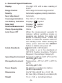
1
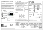
OPERATOR’S
INSTRUCTION MANUAL
ST-3030
3¾ AC/DC DIGITAL
CLAMP METER
Copyright © 2008 Elenco® Electronics, Inc.
Contents
1. Safety Information
3
2. Safety Symbols
4
3. General Specifications
5
4. Introduction
6
5. Features
6
6. Specifications
6,7
7. Display Details
8,9
8. Electrical Specifications
10-12
9. Operation
12-15
10. Battery Replacement
16
11. Maintenance
16
!
WARNING !
PLEASE READ THIS INSTRUCTION MANUAL
CAREFULLY
Misuse and/or abuse of this instruction manual cannot be prevented by
any printed word and may cause injury and/or equipment damage.
Please follow all these instructions and measurement procedures
carefully, and adhere to all standard industry safety rules and practices.
The multimeter shall be used in over voltage category II !
-2-
1. Safety Information
To ensure that the meter is used safely, follow all of the safety and
operation instructions in this manual. If the meter is not used as
described in the manual, the safety features of the meter might be
impaired.
• Do not use the meter if the meter or the test leads look damaged,
or if you suspect that the meter is not operating properly.
• Turn off the power to the circuit under test before cutting,
unsoldering, or breaking the circuit. Small amounts of current
can be dangerous.
• Use caution when working above 60VDC or 30VAC rms. Such
voltages pose a shock hazard.
• When using the test lead, keep your fingers behind the guards on
the test lead.
• Disconnect the live test lead before disconnecting the common
test lead.
• Check the main function dial and make sure it is at the correct
position before each measurement.
• Do not perform resistance, capacitance, temperature, diode and
continuity test on a live power system.
• Do not apply voltage between the test terminals and test terminal
to ground that exceed the maximum limit record in this manual.
• Keep the fingers after the protection ring when measuring
through the clamp.
• Change the battery when the “ +
incorrect data.
” symbol appears to avoid
• Use the DMM indoor, altitude up to 6,562 ft. (2,000m) and
temperatures between 41OF and 104OF (5OC - 40OC). Maximum
relative humidity 80% for temperatures up to 88OF (31OC),
decreasing linearly to 50% relative humidity at 104OF (40OC).
• In locations subject to radio frequency interface, the product may
malfunction. It will reset automatically when leaving that
environment.
-3-
2. Safety Symbols
!
This marking adjacent to another marking, terminal,
or operating device indicates that the operator must
refer to the explanation in the operating instructions
to avoid damage to the equipment and/or to avoid
personal injury.
WARNING
This WARNING sign denotes a hazard. It calls
attention to a procedure, practice or the like, which if
not correctly performed or adhered to, could result in
personal injury.
CAUTION
This CAUTION sign denotes a hazard. It calls
attention to a procedure, practice or the like, which, if
not correctly adhered to, could result in damage to or
destruction of part or all of the instrument.
500V max.
This marking advises the user that the terminal(s) so
marked must not be connected to a circuit point at
which the voltage, with respect to earth ground,
exceeds (in this case) 500 volts.
This symbol, adjacent to one or more terminals,
identifies them as being associated with ranges that
may in normal use be subjected to particularly
hazardous voltages.
For maximum safety, the instrument and its test leads
should not be handled when these terminals are
energized.
This marking indicates that equipment is protected
completely by the double insulation.
~
~
Alternating Current (AC)
Direct Current (DC)
Either DC or AC
This symbol indicates separate collection for
electrical and electronic equipment.
-4-
3. General Specifications
Display
3¾ digit LCD with a max. reading of
4,000
Range Control
Auto range & manual range control
Polarity
Automatic negative polarity indication
Zero Adjustment
Automatic
Overrange Indication
The “OL” or “–OL” display
Low Battery Indication
Displays “
Data Hold
Displays “ H ” symbol
+
” symbol
Relative Measurement
Displays “” symbol
Clamp Opening Size
32mm
Auto Power Off
When the measurement exceeds 10
minutes without switching modes or
pressing any buttons, the meter will
switch to standby mode. Press any
button or rotate the selector switch to
exit standby mode. When reseting the
meter, press and hold the SELECT
button to disable auto power off.
Safety Standards
EMC/LVD. CAT III 600V
The meter is up to the standards of
IEC1010 Double Insulation, Pollution
Degree 2, Overvoltage Category III.
Operating Environment Temperature 32OF to 104OF (0OC to 40OC)
Humidity ≤ 80% RH
Storage Environment
Temperature –4OF to 140OF (–20OC to
60OC)
Humidity ≤ 90% RH
Power Supply
9V alkaline or carbon zinc battery
(6F22 or equivalent)
Dimensions
3 5/16” (W) x 8 5/8” (L) x 1 3/4” (D)
84.1mm (W) x 219mm (L) x 44.5mm (D)
Weight
12 oz. / 340 g. (including battery)
-5-
4. Introduction
The Elenco® ST-3030 is a 3¾ (4,000 count) AC/DC digital clamp
ammeter and multitester. It performs the basic electrical
measurements required by service technicians. It measures
AC/DC voltages, AC/DC current and resistance. It also has a diode
test function and a continuity beeper. Other features include data
hold min/max memory and auto power off. It is overload protected.
5. Features
• 3¾ digit, 4,000 count display
• AC/DC clamp-on meter
• Auto/manual range
• Basic accuracy: 0.5%
• Diode check/continuity buzzer
• Relative measurement
• Data hold
• Back light
• Auto power off
• CE/LVD CAT III 600V
6. Specifications
DC Voltage
400mV/4/40/400V ±0.5%, 600V ±0.8%
AC Voltage
4/40/400V ±1.0%, 400mV/600V ±0.8%
DC Current
400A ±1.5%, 1,000A ±2.0%
AC Current
400A ±2.0%, 1,000A ±2.5%
Resistance
400Ω/4k/40k/400kΩ/4MΩ ±1.0%,
40MΩ ±2.0%
Capacitance
40nF ±3%, 400nF/4μF ±2.5%, 40/100μF ±5%
Frequency
10Hz - 10MHz ±1.0%
Duty Cycle
0.1% - 99.9% ±2.0%
Temperature
–4OF - 302OF ±(5OF +2)
302OF - 1,472OF ±(3% +2OF)
-6-
13
1
2
12
3
4
11
5
10
6
9
7
8
1. Transformer Jaws
2. Barrier - Hand guard holds meter
below this barrier. DO NOT touch any
bare wires that the jaws may be
clamped around.
3. Data Hold / Light Button - Holds
reading in display when the D-Hold
button is pressed and released. Also
turns on the back light.
4. Rotary Select Switch - Selects the
function and range to measure.
5. LCD Display - Provides the
measurement indications and other
instrument status.
6. Hz/Duty Button - When the selector
switch is set to Hz or V~, this button
allows the selection of Frequency
Measurement (Hz) mode or the duty
cycle measurement (duty) mode.
7. VΩHz Jack - The red test lead is
inserted into this jack for all
measurements except current (amps).
8. COM Jack - The black test lead is
plugged into this jack for all
measurements
except
current
(amps).
9. Range Button - Press this button to
obtain the desired measurement
range.
10. Select Button - Press this button to
access the alternate measurement
modes.
11. REL and DCA Zero Adjust Press this button to enter the
Relative mode, zero the display, and
store the displayed reading as a
reference value.
12. Trigger - Opens and closes the
clamp jaws.
13. Centering Marks - Locators for
positioning the conductor within the
jaws to obtain specified accuracy.
-7-
7. Display Details
Auto
The Auto (ranging) annunciator is on when the meter is set
to a function that has multiple ranges available. The meter is
completely automatic and does not require the user to select
a range.
~
The AC ~ annunciator is on when the meter is set to
measure AC voltage or current.
Negative Sign Annunciator - This annunciator is displayed
when DC voltage being measured by the VΩHz jack is
negative in respect to the COM jack. It can also be displayed
in the A
mode, when the measured current is in the
reverse direction of the polarity arrow. Note: Polarity arrow
indicates current flow from positive to negative.
+
Low Battery Annunciator - This annunciator is displayed
when the battery needs to be replaced.
H
Hold Annunciator - This annunciator is displayed any time
the hold mode is active.
REL Annunciator - This annunciator is displayed whenever
the REL mode or the DCA ZERO-ADJ mode is active.
Continuity Annunciator - This annunciator is displayed
whenever the Continuity (Beeper) mode is selected.
Diode Test Annunciator - This annunciator is displayed
whenever the Diode Test mode is selected.
%
Percent Annunciator - This annunciator is displayed
whenever the Duty Cycle mode is selected.
-8-
F
Fahrenheit Annunciator - This annunciator is displayed
whenever the Temperature measurement mode is selected
for Fahrenheit display.
C
Centrigrade Annunciator - This annunciator is displayed
whenever the Temperature measurement mode is selected
for Centrigrade display.
O
O
Ω
kΩ
MΩ
Resistance (Ohms) Annunciators - These annunciators
are displayed whenever Resistance is being measured. The
displayed annunciator indicates the range of resistance that
is being measured.
mV, V
Voltage Annunciators - These annunciators are displayed
whenever Voltage is being measured. The displayed annunciator
indicates the range of voltage that is being measured.
A
Current (Amperes) Annunciator - This annunciator is
displayed whenever the Current (Amps) measurement mode
is active.
nF
μF
mF
Hz
kHz
MHz
Capacitance (Farads) Annunciators - These annunciators
are displayed whenever Capacitance is being measured.
The displayed annunciator indicates the range of
capacitance that is being measured.
Frequency (Hertz) Annunciators - These annunciators are
displayed whenever Frequency is being measured. The
displayed annunciator indicates the range of frequency that
is being measured.
APO
Auto Power Annunciator - This annunciator is displayed when
the Auto Power Off mode is active. APO comes on
automatically when the meter is turned on. To defeat the APO,
hold the SELECT button down when turning on the power.
MAX
MIN
MAX and MIN Annunciators - These annunciators are
displayed when either MAX or MIN display has been selected
(by pressing the MAX/MIN button). To exit this mode, press
and hold the MAX/MIN button until the meter returns to the
normal operating mode (takes about two seconds.
Overload Indication - This is the display when the input
exceeds the display capability of the Meter. If measuring
voltage or current, remove the input immediately. Depending
on the meter setting, the decimal points may or may not be
present.
-9-
8. Electrical Specifications
Accuracies are ±(% of reading + number in last digit) at 29 ±5OC, <75% RH
DC Voltage
Range
400mV
4V
40V
400V
600V
Accuracy
±(0.5% + 2)
±(0.8% + 3)
Resolution
0.1mV
1mV
10mV
100mV
1V
Overload Protection: 600VDC or AC rms
Impedance: 10MΩ. More than 100MΩ on 400mV range
AC Voltage
Range
Accuracy
Resolution
400mV
4V
40V
400V
600V
±(1.5% + 3)
0.1mV
1mV
10mV
100mV
1V
±(1.0% + 2)
±(1.5% + 3)
The 400mV range can be selected by pressing the “RANGE” key only.
Average sensing, calibrated to rms of sine wave.
Frequency: 40~400Hz
Overload Protection: 600VDC or AC rms
Impedance: 10MΩ. More than 100MΩ on 400mV range
DC Current
Range
Accuracy
400A
±(1.5% + 5)
1,000A
±(2.0% + 10)
Overload Protection: 1,000A DC or AC rms
AC Current
Range
Accuracy
400A
±(2.0% + 5)
1,000A
±(2.5% + 10)
Average Sensing, calibrated to rms of sine wave
Frequency: 40~100Hz
Overload Protection: 1,000A DC or AC rms
-10-
Resolution
0.1A
1A
Resolution
0.1A
1A
Resistance
Range
400Ω
4kΩ
40kΩ
400kΩ
4MΩ
40MΩ
Accuracy
Resolution
0.1Ω
1Ω
10Ω
100Ω
1kΩ
10kΩ
±(1.0% + 2)
±(2.0% + 3)
Overload Protection: 250VDC or AC rms
Capacitance
Range
40nF
400nF
4μF
40μF
100μF
Accuracy
Resolution
10pF
100pF
1nF
10nF
100nF
±(3.0% + 10)
±(2.5% + 5)
±(5.0% + 10)
Overload Protection: 250VDC or AC rms
Diode and Audible Continuity Test
Range
Description
Display read approximately
forward voltage of diode
Test Condition
Forward DC current approx. 0.4mA
Reversed DC voltage approx. 1.5V
Built-in buzzer sounds if Open circuit voltage approx. 0.5V
resistance is less than 120Ω
Overload Protection: 250VDC or AC rms
Frequency
Range
10Hz
100Hz
1kHz
10kHz
100kHz
1MHz
10MHz
Accuracy
Resolution
±(0.1% + 5)
0.01Hz
0.1Hz
1Hz
10Hz
100Hz
1kHz
10kHz
Sensitivity: sine wave 0.6V rms (10MHz: 1.5V rms)
Overload Protection: 250VDC or AC rms
-11-
Duty Cycle
0.1%~99.9%: ±(2.0% +2) Frequency lower than 10kHz
Sensitivity: sine wave 0.6V rms
Overload Protection: 200VDC or AC rms
Temperature
Range
F
O
Accuracy
–4~302OF
302~1472OF
Resolution
±(5OF + 2)
±(3% + 2)
1OF
NiCr-NiSi sensor
Overload Protection: 250VDC or AC rms
9. Operation
DC and AC Voltage Measurement
1. Connect the black test lead to the “COM” socket and the red test
lead to the “VΩHz” socket.
2. Set the selector switch to the desired “V~” position.
3. Press the “SELECT” button to choose the “DC” or “AC”
measurement.
4. Measure the voltage by touching the test lead tips to the test
circuit where the value of voltage is needed.
5. Read the result on the LCD panel.
6. With the meter on the AC range, press the “Hz/DUTY” button to
measure the frequency or duty cycle.
DC Current Measurement
1. Set the selector switch to the desired “A
” position.
2. Zero the reading by pressing the “REL (DCA ZERO ADJ)
button.
3. Disconnect the test leads from the meter.
4. Clamp the jaws around the one conductor to be measured.
Center the conductor within the jaw useing the centering mark as
guides.
5. Read the result on the LCD panel. The arrow on the jaw
indicates the direction of positive current flow (positive to
negative).
-12-
AC Current Measurement
1. Set the selector switch to the desired “A~” position.
2. Disconnect the test leads from the meter.
3. Clamp the jaws around the one conductor to be measured.
Center the conductor within the jaw using the centering marks
as guides.
4. Read the result on the LCD panel.
Resistance Measurement
1. Connect the black test lead to the “COM” socket and the red test
lead to the “VΩHz” socket.
) ” position.
2. Set the selector switch to the desired “Ω 3. Press the “SELECT” button to choose the resistance measurement.
4. Connect the tips of the test leads to the points where the value
of the resistance is needed.
5. Read the result from the LCD panel.
Note: When taking the resistance value from a circuit system, make
sure the power is disconnected and all capacitors are discharged.
Capacitance Measurement
1. Connect the black test lead to the “COM” socket and the red test
lead to the “VΩHz” socket.
) ” position.
2. Set the selector switch to the desired “Ω 3. Press the “SELECT” button to choose the capacitance measurement.
4. Connect the tips of the test leads to the points where the value
of the capacitance is needed.
5. Read the result from the LCD panel.
Note:
a) Before testing, discharge the capacitors by shorting the leads together.
Use caution when handling capacitors because they may have a
considerable charge on them before discharging.
b) Before testing, pres the “REL (DCA ZERO ADJ)” button to eliminate the
zero error.
c) When testing 100μF capacitors, note that there will be a time lag of
approximately 15 seconds.
-13-
Diode and Audible Continuity Test
1. Connect the black test lead to “COM” socket and the red test lead
to the “VΩHz” socket.
) ” position.
2. Set the selector switch to desired “Ω 3. Press the “SELECT” button to choose either a diode or audible
continuity measurement.
4. Connect the test leads across the diode under measurement, the
display shows the approximate forward voltage of this diode.
5. Connect the test leads to two points of a circuit. If the resistance
is lower that approximately 120Ω, the buzzer will sound.
Note: Make sure the power is disconnected and all capacitors
discharged before taking this measurement.
Frequency and Duty Cycle Measurement
1. Connect the black test lead to “COM” socket and the red test lead
to the “VΩHz” socket.
2. Set the selector switch to desired “Hz” position.
3. Press the “Hz/DUTY” button to choose either a frequency or
duty cycle measurement.
4. Connect the probe across the source or load under
measurement.
5. Read the result on the LCD panel.
Temperature Measurement
1. Connect the black test lead to “COM” socket and the red test lead
to the “VΩHz” socket.
2. Set the selector switch to desired “F” position.
3. Put the sensor probe into the temperature field under
measurement.
4. Read the result on the LCD panel.
Data Hold
On any range, press the “D.HOLD” button to lock the display value,
and the “ H ” symbol will appear on the display. Press it again to
exit.
-14-
Back Light
On any range, press the “D.HOLD” button for over two seconds to
light the backlight. Press it again for more than two seconds to wink
the light.
Relative Measurement
Press the “REL” button. You can measure the relative value and
the “” symbol will appear on the display. The auto range mode will
be changed to manual mode. Press it again to exit the relative
measurement and the “” symbol will disappear, but you cannot
return to the auto range mode. This function can be used to zero
the reading on the DCA range. This function is non-effective on the
Hz/DUTY measurement.
Auto/Manual Range
The auto range mode is a convenient function, but it might be faster
to manually set the range when you measure values that you know
to be within a certain range.
To select the manual range, press the “RANGE” button repeatedly
until the display shows the desired range. The range steps upward
as you press the “RANGE” button.
The meter will go back to auto range mode when you press the
“RANGE” button for more than two seconds. It cannot select the
manual range mode on Hz/DUTY, capacitance, or temperature
ranges.
Caution: While using the manual range mode, if “OL” appears on
the display, immediately set the clamp meter to a higher range.
-15-
10. Battery Replacement
1. When the battery voltage drops below the proper operating
range, the “ + ” (low battery) symbol will appear on the LCD
display.
2. Before changing the battery, set the selector switch to the “OFF”
position. Open the battery compartment cover with a phillips
screwdriver.
3. Replace the old battery with a new one of the same type.
4. Close the battery cover and secure it with the screw.
Caution: Properly dispose of the batteries as stated in your local
rules and regulations.
Note: There are no fuses in this meter.
11. Maintenance
1. Before you open the battery cover, disconnect both test leads
and never use the meter while the battery cover is removed.
2. To avoid contamination or static damage, do not touch the circuit
board without proper static protection.
3. If the meter is not going to be used for a long time, take out the
battery and do not store the meter in high temperature or high
humidity environment.
4. While taking a current measurement, keep the cable at the center
of the clamp to achieve an accurate test result.
5. Repairs or servicing not covered in this manual should only be
performed by qualified personnel.
6. Periodically wipe the case with a dry cloth and detergent. Do not
use abrasives or solvents on the meter.
Elenco® Electronics, Inc.
150 Carpenter Avenue
Wheeling, IL 60090
(847) 541-3800
Website: www.elenco.com
e-mail: [email protected]