1
CÓPIA NÃO CONTROLADA
M047
SERVICE MANUAL
005630MIU
CÓPIA NÃO CONTROLADA
CÓPIA NÃO CONTROLADA
CÓPIA NÃO CONTROLADA
CÓPIA NÃO CONTROLADA
M047
SERVICE MANUAL
CÓPIA NÃO CONTROLADA
CÓPIA NÃO CONTROLADA
CÓPIA NÃO CONTROLADA
CÓPIA NÃO CONTROLADA
M047
SERVICE MANUAL
00M047MIU
CÓPIA NÃO CONTROLADA
CÓPIA NÃO CONTROLADA
CÓPIA NÃO CONTROLADA
CÓPIA NÃO CONTROLADA
It is the reader's responsibility when discussing the information contained
within this document to maintain a level of confidentiality that is in the best
interest of Ricoh Americas Corporation and its member companies.
NO PART OF THIS DOCUMENT MAY BE REPRODUCED IN ANY
FASHION AND DISTRIBUTED WITHOUT THE PRIOR
PERMISSION OF RICOH AMERICAS CORPORATION.
All product names, domain names or product illustrations, including
desktop images, used in this document are trademarks, registered
trademarks or the property of their respective companies.
They are used throughout this book in an informational or editorial fashion
only and for the benefit of such companies. No such use, or the use of
any trade name, or web site is intended to convey endorsement or other
affiliation with Ricoh products.
© 2010 RICOH Americas Corporation. All rights reserved.
CÓPIA NÃO CONTROLADA
CÓPIA NÃO CONTROLADA
CÓPIA NÃO CONTROLADA
CÓPIA NÃO CONTROLADA
WARNING
The Service Manual contains information
regarding service techniques, procedures,
processes and spare parts of office equipment
distributed by Ricoh Americas Corporation.
Users of this manual should be either service
trained or certified by successfully completing a
Ricoh Technical Training Program.
Untrained and uncertified users utilizing
information contained in this service manual to
repair or modify Ricoh equipment risk personal
injury, damage to property or loss of warranty
protection.
Ricoh Americas Corporation
CÓPIA NÃO CONTROLADA
CÓPIA NÃO CONTROLADA
CÓPIA NÃO CONTROLADA
CÓPIA NÃO CONTROLADA
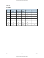
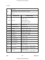
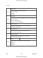
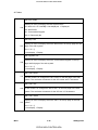
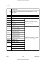
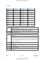
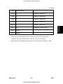
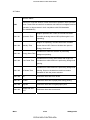
LEGEND
PRODUCT
CODE
M047
GESTETNER
SP 6330N
COMPANY
LANIER
RICOH
LP235N
SP 6330N
SAVIN
MLP235n
DOCUMENTATION HISTORY
REV. NO.
*
DATE
01/2010
COMMENTS
Original Printing
CÓPIA NÃO CONTROLADA
CÓPIA NÃO CONTROLADA
CÓPIA NÃO CONTROLADA
CÓPIA NÃO CONTROLADA
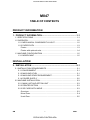
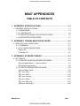
M047
TABLE OF CONTENTS
PRODUCT INFORMATION
1. PRODUCT INFORMATION...........................................................1-1 1.1 SPECIFICATIONS ..................................................................................... 1-1 1.2 OVERVIEW ................................................................................................ 1-2 1.2.1 MECHANICAL COMPONENT LAYOUT ........................................... 1-2 1.2.2 PAPER PATH ................................................................................... 1-3 Printer ................................................................................................... 1-3 Printer with optional units ..................................................................... 1-4 1.3 MACHINE CONFIGURATION ................................................................... 1-5 1.3.1 MODEL M047 ................................................................................... 1-5
INSTALLATION
2. INSTALLATION ............................................................................2-1 2.1 INSTALLATION REQUIREMENTS ............................................................ 2-1 2.1.1 ENVIRONMENT ............................................................................... 2-1 2.1.2 MACHINE LEVEL ............................................................................. 2-1 2.1.3 MACHINE SPACE REQUIREMENT ................................................. 2-2 2.1.4 POWER SUPPLY ............................................................................. 2-2 2.2 MACHINE INSTALLATION ........................................................................ 2-3 2.2.1 MAIN UNIT AND OPTION UNIT ....................................................... 2-3 2.2.2 PRINTER OPTION ........................................................................... 2-3 2.2.3 SD CARD APPLI MOVE ................................................................... 2-3 Overview .............................................................................................. 2-3 Move Exec............................................................................................ 2-4 Undo Exec ............................................................................................ 2-5
SM
i
CÓPIA NÃO CONTROLADA
M047
CÓPIA NÃO CONTROLADA
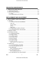
PREVENTIVE MAINTENANCE
3. PREVENTIVE MAINTENANCE ....................................................3-1 3.1 USER MAINTENANCE .............................................................................. 3-1 3.2 SERVICE MAINTENANCE ........................................................................ 3-2 3.2.1 MAIN ................................................................................................. 3-2 3.2.2 PAPER FEED UNIT (OPTION) ......................................................... 3-3
REPLACEMENT AND ADJUSTMENT
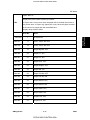
4. REPLACEMENT AND ADJUSTMENT .........................................4-1 4.1 GENERAL .................................................................................................. 4-1 4.1.1 PRECAUTIONS ON DISASSEMBLY ............................................... 4-1 Laser unit.............................................................................................. 4-1 Transfer Roller...................................................................................... 4-2 Fusing .................................................................................................. 4-2 Paper Feed........................................................................................... 4-2 4.1.2 RELEASING PLASTIC LATCHES .................................................... 4-2 4.1.3 AFTER SERVICING THE MACHINE ................................................ 4-3 4.2 SPECIAL TOOLS ....................................................................................... 4-4 4.3 EXTERIOR COVERS................................................................................. 4-5 4.3.1 OPERATION PANEL ........................................................................ 4-5 4.3.2 REAR COVER .................................................................................. 4-6 4.3.3 UPPER COVER ................................................................................ 4-6 4.3.4 BY-PASS TRAY ................................................................................ 4-7 4.3.5 LEFT COVER ................................................................................... 4-8 4.3.6 FRONT DOOR .................................................................................. 4-9 4.3.7 RIGHT COVER ............................................................................... 4-10 Tab Locations on the Right Cover ...................................................... 4-11 4.4 LASER UNIT ............................................................................................ 4-12 4.4.1 CAUTION DECAL LOCATION........................................................ 4-12 4.4.2 POLYGON MIRROR MOTOR ........................................................ 4-13 4.4.3 LASER UNIT ................................................................................... 4-14 When reinstalling the laser unit .......................................................... 4-15 4.4.4 LASER DIODE UNIT ...................................................................... 4-16 When installing the LD Unit: ............................................................... 4-16 4.4.5 LASER BEAM PITCH ADJUSTMENT ............................................ 4-17 M047
ii
CÓPIA NÃO CONTROLADA
SM
CÓPIA NÃO CONTROLADA
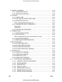
4.5 IMAGE TRANSFER ................................................................................. 4-18 4.5.1 TRANSFER ROLLER ..................................................................... 4-18 4.5.2 TONER END SENSOR ................................................................... 4-19 4.6 FUSING ................................................................................................... 4-20 4.6.1 FUSING UNIT ................................................................................. 4-20 4.6.2 HOT ROLLER AND FUSING LAMP ............................................... 4-21 4.6.3 PRESSURE ROLLER ..................................................................... 4-24 When reassembling the fusing unit .................................................... 4-25 4.6.4 THERMISTOR AND THERMOSTAT .............................................. 4-26 Thermostat ......................................................................................... 4-26 Thermistor .......................................................................................... 4-26 4.6.5 HOT ROLLER STRIPPERS ............................................................ 4-28 4.7 PAPER FEED .......................................................................................... 4-29 4.7.1 PAPER FEED ROLLER .................................................................. 4-29 4.7.2 FRICTION PAD ............................................................................... 4-30 When reinstalling the friction pad follow this order ............................. 4-30 4.7.3 PAPER END SENSOR ................................................................... 4-31 4.7.4 REMAINING PAPER SENSORS .................................................... 4-32 4.8 BY-PASS FEED ....................................................................................... 4-33 4.8.1 BY-PASS FEED UNIT .................................................................... 4-33 4.8.2 BY-PASS FEED ROLLER............................................................... 4-34 4.8.3 BY-PASS FRICTION PAD .............................................................. 4-35 4.8.4 BY-PASS PAPER SET SENSOR ................................................... 4-37 4.9 PAPER EXIT ............................................................................................ 4-38 4.9.1 PAPER EXIT SENSOR ................................................................... 4-38 4.9.2 OVERFLOW SENSOR ................................................................... 4-38 4.9.3 PAPER EXIT UNIT ......................................................................... 4-39 4.9.4 FUSING EXIT SENSOR ................................................................. 4-40 4.10 ELECTRICAL COMPONENTS........................................................... 4-41 4.10.1 PRINTER CONTROLLER BOARD ............................................. 4-41 4.10.2 ENGINE BOARD ........................................................................ 4-42 4.10.3 MAIN MOTOR............................................................................. 4-43 4.10.4 RELAY CLUTCH......................................................................... 4-43 4.10.5 PAPER FEED CLUTCH .............................................................. 4-44 4.10.6 REGISTRATION CLUTCH ......................................................... 4-46 4.10.7 REGISTRATION SENSOR ......................................................... 4-47 SM
iii
CÓPIA NÃO CONTROLADA
M047
CÓPIA NÃO CONTROLADA
4.10.8 POWER SUPPLY BOARD AND HIGH VOLTAGE SUPPLY
BOARD 4-48 4.10.9 FUSING PRESSURE SENSOR.................................................. 4-50 4.10.10 FUSING FAN ............................................................................ 4-51 4.10.11 PSU FAN .................................................................................. 4-51 4.11 IMAGE ADJUSTMENT ....................................................................... 4-52 4.11.1 REGISTRATION ADJUSTMENT ................................................ 4-52 4.11.2 PARALLELOGRAM IMAGE ADJUSTMENT ............................... 4-52
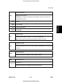
SYSTEM MAINTENANCE REFERENCE
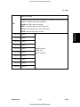
5. SYSTEM MAINTENANCE REFERENCE .....................................5-1 5.1 SERVICE PROGRAM MODE .................................................................... 5-1 5.1.1 SP TABLES ...................................................................................... 5-1 Before accessing the service menu, do the following: .......................... 5-1 5.1.2 INPUTTING A VALUE OR SETTING FOR A SERVICE PROGRAM
5-1 5.1.3 EXITING SERVICE MODE ............................................................... 5-2 5.2 UPDATING THE FIRMWARE .................................................................... 5-3 5.2.1 TYPE OF FIRMWARE ...................................................................... 5-3 5.2.2 PRECAUTIONS ................................................................................ 5-4 Handling SD Cards ............................................................................... 5-4 Upload/Download ................................................................................. 5-4 Network Connection ............................................................................. 5-4 5.2.3 MACHINE FIRMWARE UPDATE ..................................................... 5-5 5.2.4 ERROR RECOVERY ........................................................................ 5-7 Controller .............................................................................................. 5-7 Engine .................................................................................................. 5-8 5.3 POWER-ON SELF TESTS ........................................................................ 5-9 5.4 DIP SWITCHES ....................................................................................... 5-10 5.4.1 CONTROLLER BOARD .................................................................. 5-10
M047
iv
CÓPIA NÃO CONTROLADA
SM
CÓPIA NÃO CONTROLADA
TROUBLESHOOTING
6. TROUBLESHOOTING ..................................................................6-1 6.1 SERVICE CALL CONDITIONS .................................................................. 6-1 6.2 ELECTRICAL COMPONENT DEFECTS ................................................... 6-2 6.2.1 SENSORS ........................................................................................ 6-2 6.2.2 SWITCHES ....................................................................................... 6-4 6.2.3 BLOWN FUSE CONDITIONS ........................................................... 6-5 6.2.4 LEDS ................................................................................................ 6-5 7. ENERGY SAVING .........................................................................7-1 7.1 ENERGY SAVE ......................................................................................... 7-1 7.1.1 ENERGY SAVER MODES................................................................ 7-1 Energy Saver Mode Setting.................................................................. 7-1 Return to Standby Mode ...................................................................... 7-2 7.2 PAPER SAVE ............................................................................................ 7-3 7.2.1 EFFECTIVENESS OF DUPLEX/COMBINE FUNCTION .................. 7-3 1. Duplex: ............................................................................................. 7-3 2. Combine mode: ................................................................................ 7-3 3. Duplex + Combine: ........................................................................... 7-4 Recommendation ................................................................................. 7-4 Duplex Mode Tables ............................................................................ 7-5 G806(DUPLEX UNIT TYPE AD610)
SEE SECTION G806 FOR DETAILED TABLE OF CONTENTS
M374 (PAPER FEED UNIT PB3090)
SEE SECTION M374 FOR DETAILED TABLE OF CONTENTS
SM
v
CÓPIA NÃO CONTROLADA
M047
CÓPIA NÃO CONTROLADA
CÓPIA NÃO CONTROLADA
PREVENTIVE MAINTENANCE
APPENDIX: SP MODE TABLES
REPLACEMENT AND ADJUSTMENT
SYSTEM MAINTENANCE REFERENCE
G806 (Duplex Unit Type AD610)
TROUBLESHOOTING
TAB
POSITION 8
TAB
POSITION 7
ENERGY SAVING
TAB
POSITION 2
M374 (Paper Feed Unit PB3090)
TAB
POSITION 3
APPENDIX: TROUBLESHOOTING GUIDE
TAB
POSITION 4
INSTALLATION
TAB
POSITION 5
APPENDIX: SPECIFICATIONS
TAB
POSITION 6
PRODUCT INFORMATION
TAB
POSITION 1
CÓPIA NÃO CONTROLADA
CÓPIA NÃO CONTROLADA
CÓPIA NÃO CONTROLADA
CÓPIA NÃO CONTROLADA
CÓPIA NÃO CONTROLADA
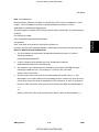
Read This First
Safety Notices
Important Safety Notices
Prevention of Physical Injury
1.
Before disassembling or assembling parts of the machine and peripherals, make sure
that the machine power cord is unplugged.
2.
The wall outlet should be near the machine and easily accessible.
3.
If any adjustment or operation check has to be made with exterior covers off or open
while the main switch is turned on, keep hands away from electrified or mechanically
driven components.
4.
The machine drives some of its components when it completes the warm-up period.
Be careful to keep hands away from the mechanical and electrical components as the
machine starts operation.
5.
The inside and the metal parts of the fusing unit become extremely hot while the
machine is operating. Be careful to avoid touching those components with your bare
hands.
Health Safety Conditions
Toner is non-toxic, but if you get either of them in your eyes by accident, it may cause
temporary eye discomfort. Try to remove with eye drops or flush with water as first aid. If
unsuccessful, get medical attention.
Observance of Electrical Safety Standards
The machine and its peripherals must be serviced by a customer service representative
who has completed the training course on those models.
The Controller board on this machine contains a lithium battery. The danger of
explosion exists if a battery of this type is incorrectly replaced. Replace only with
the same or an equivalent type recommended by the manufacturer. Discard
batteries in accordance with the manufacturer's instructions and local regulations.
CÓPIA NÃO CONTROLADA
CÓPIA NÃO CONTROLADA
Safety and Ecological Notes for Disposal
1.
Do not incinerate toner bottles or used toner. Toner dust may ignite suddenly when
exposed to an open flame.
2.
Dispose of used toner, the maintenance unit which includes developer or the organic
photoconductor in accordance with local regulations. (These are non-toxic supplies.)
3.
Dispose of replaced parts in accordance with local regulations.
To prevent a fire or explosion, keep the machine away from flammable liquids,
gases, and aerosols. A fire or an explosion might occur.
Handling Toner
Work carefully when removing paper jams or replacing toner bottles or cartridges to
avoid spilling toner on clothing or the hands.
If toner is inhaled, immediately gargle with large amounts of cold water and move to a
well ventilated location. If there are signs of irritation or other problems, seek medical
attention.
If toner gets on the skin, wash immediately with soap and cold running water.
If toner gets into the eyes, flush the eyes with cold running water or eye wash. If there
are signs of irritation or other problems, seek medical attention.
If toner is swallowed, drink a large amount of cold water to dilute the ingested toner. If
there are signs of any problem, seek medical attention.
If toner spills on clothing, wash the affected area immediately with soap and cold water.
Never use hot water! Hot water can cause toner to set and permanently stain fabric.
Always store toner and developer supplies such as toner and developer packages,
cartridges, and bottles (including used toner and empty bottles and cartridges) out of
the reach of children.
Always store fresh toner supplies or empty bottles or cartridges in a cool, dry location
that is not exposed to direct sunlight.
CÓPIA NÃO CONTROLADA
CÓPIA NÃO CONTROLADA
Laser Safety
The Center for Devices and Radiological Health (CDRH) prohibits the repair of laser-based
optical units in the field. The optical housing unit can only be repaired in a factory or at a
location with the requisite equipment. The laser subsystem is replaceable in the field by a
qualified Customer Engineer. The laser chassis is not repairable in the field. Customer
engineers are therefore directed to return all chassis and laser subsystems to the factory or
service depot when replacement of the optical subsystem is required.
Use of controls, or adjustment, or performance of procedures other than those
specified in this manual may result in hazardous radiation exposure.
WARNING
WARNING:
Turn off the main switch before attempting any of the procedures in the Laser Unit
section. Laser beams can seriously damage your eyes.
CAUTION MARKING:
CÓPIA NÃO CONTROLADA
CÓPIA NÃO CONTROLADA
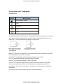
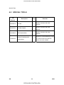
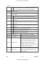
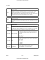
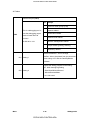
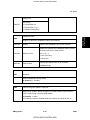
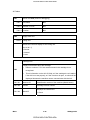
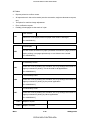
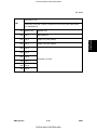
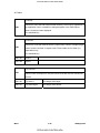
Conventions and Trademarks
Conventions
Symbol
What it means
Refer to section number
Screw
Connector
E-ring
C-ring
The following notations are used in text to describe the direction of paper feed: lengthwise
and sideways. The annotations "SEF" and "LEF" denote "Short Edge Feed" and "Long
Edge Feed.” (The arrows indicate the direction of paper feed.)
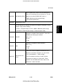
Trademarks
Microsoft®, Windows®, and MS-DOS® are registered trademarks of Microsoft Corporation
in the United States and /or other countries.
PostScript® is a registered trademark of Adobe Systems, Incorporated.
PCL® is a registered trademark of Hewlett-Packard Company.
Ethernet® is a registered trademark of Xerox Corporation.
PowerPC® is a registered trademark of International Business Machines Corporation.
Other product names used herein are for identification purposes only and may be
trademarks of their respective companies. We disclaim any and all rights involved with
those marks.
This manual uses several symbols and some simple abbreviations.
CÓPIA NÃO CONTROLADA
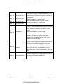
CÓPIA NÃO CONTROLADA
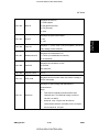
PRODUCT INFORMATION
R E V I S I O N H I S T O RY
P a ge
Date
A d de d /U pd at e d /N ew
None
CÓPIA NÃO CONTROLADA
CÓPIA NÃO CONTROLADA
CÓPIA NÃO CONTROLADA
CÓPIA NÃO CONTROLADA
Product
Information
Specifications
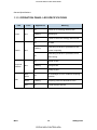
1. PRODUCT INFORMATION
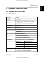
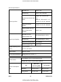
1.1 SPECIFICATIONS
See "Appendices" for the "General Specifications.”
M047
1-1
CÓPIA NÃO CONTROLADA
SM
CÓPIA NÃO CONTROLADA
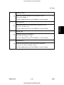
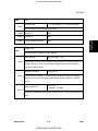
Overview
1.2 OVERVIEW
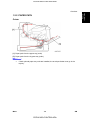
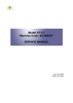
1.2.1 MECHANICAL COMPONENT LAYOUT
1: Laser unit
2: Charge roller
3: Development roller
4: Cartridge (AIO-type)
5: By-pass feed tray
6: By-pass feed roller
7: Paper feed roller
8: Friction pad
SM
9: Registration roller
10: Transfer roller
11: Drum
12: Pressure roller
13: Hot roller
14: Paper exit roller
15: Quenching lamp
1-2
CÓPIA NÃO CONTROLADA
M047
CÓPIA NÃO CONTROLADA
Product
Information
Overview
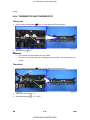
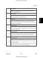
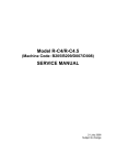
1.2.2 PAPER PATH
Printer
[A]: Paper path from the paper tray (main)
[B]: Paper path from the by-pass tray (main)
If both optional paper tray units are installed, the envelope feeder must go in the
top tray.
M047
1-3
CÓPIA NÃO CONTROLADA
SM
CÓPIA NÃO CONTROLADA
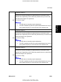
Overview
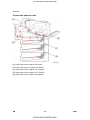
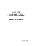
Printer with optional units
[A]: Paper path from the paper tray (main)
[B]: Paper path from the by-pass tray (main)
[C]: Paper path from the paper tray 2 (option)
[D]: Paper path from the paper tray 3 (option)
[E]: Paper path from the duplex unit (option)
SM
1-4
CÓPIA NÃO CONTROLADA
M047
CÓPIA NÃO CONTROLADA
Product
Information
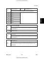
Machine Configuration
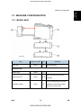
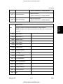
1.3 MACHINE CONFIGURATION
1.3.1 MODEL M047
Item
Machine Code
No.
M047
A
Duplex Unit
G806
B
Paper Tray Unit
M374
C, D
Main Unit
Remarks
NIB is standard.
Optional Units
Up to two tray units can be
installed.
If both optional paper trays are
Envelope Feeder
G807
C
installed, the envelope feeder
must go in the top tray.
M047
1-5
CÓPIA NÃO CONTROLADA
SM
CÓPIA NÃO CONTROLADA
CÓPIA NÃO CONTROLADA
CÓPIA NÃO CONTROLADA
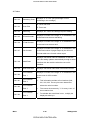
INSTALLATION
R E V I S I O N H I S T O RY
P a ge
Date
A d de d /U pd at e d /N ew
None
CÓPIA NÃO CONTROLADA
CÓPIA NÃO CONTROLADA
CÓPIA NÃO CONTROLADA
CÓPIA NÃO CONTROLADA
Installation Requirements
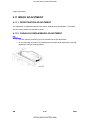
2. INSTALLATION
Installation
2.1 INSTALLATION REQUIREMENTS
2.1.1 ENVIRONMENT
This machine, which uses high voltage power sources, can generate ozone gas.
High ozone density is harmful to human health. Therefore, the machine must be
installed in a well-ventilated room.
1.
Temperature Range: 10°C to 32°C (50°F to 89.6°F)
2.
Humidity Range: 15 % to 89 % RH
3.
Ambient Illumination: Less than 2,000 lux (do not expose to direct sunlight).
4.
Ventilation: 3 times/hr/person
5.
Avoid areas that are exposed to sudden temperature changes. This includes:
Areas directly exposed to cool air from an air conditioner.
Areas directly exposed to heat from a heater.
6.
Do not install this machine in an area where it will be exposed to corrosive gases.
7.
Do not install the machine at locations over 2,000 m (6,562 ft.) above sea level.
8.
Put the machine on a strong and level base. Inclination on any side should not exceed
5 mm.
9.
Do not put the machine where it may be subjected to strong vibrations.
2.1.2 MACHINE LEVEL
Front to back: Within 5 mm. (0.2 inches) of level.
Right to left: Within 5 mm. (0.2 inches) of level.
M047
2-1
CÓPIA NÃO CONTROLADA
SM
CÓPIA NÃO CONTROLADA
Installation Requirements
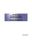
2.1.3 MACHINE SPACE REQUIREMENT
Place the machine near the power source, providing the clearance as shown below:
A: Over 10 cm (4 inches)
B: Over 10 cm (4 inches)
C: Over 10 cm (4 inches)
D: Over 10 cm (4 inches)
2.1.4 POWER SUPPLY
Make sure the plug is firmly inserted in the outlet.
Avoid multi-wiring.
Be sure to ground the machine.
120 volts, 60 Hz: More than 10 A
Input voltage level
220-240 volts, 50 Hz/60Hz: More than 6 A
Permissible voltage
Fluctuation: ±10 %
Do not set anything on the power cord
SM
2-2
CÓPIA NÃO CONTROLADA
M047
CÓPIA NÃO CONTROLADA
Machine Installation
2.2 MACHINE INSTALLATION
Installation
2.2.1 MAIN UNIT AND OPTION UNIT
Refer to the "Hardware Guide" for M041 model about the machines installation.
2.2.2 PRINTER OPTION
Refer to the "Hardware Guide" for M041 model about the machines installation. If more
than two optional applications are supposed to be installed, do "SD Card Appli Move"
described below.
IPDS option requires optional memory (128 MB or 256 MB). Install optional
memory first before installing the IPDS option. Otherwise, the machine may stall
when large print job data is sent to the machine.
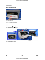
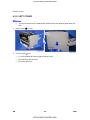
2.2.3 SD CARD APPLI MOVE
Overview
The service program "SD Card Appli Move" (SP5-873) lets you to copy application
programs from one SD card to another SD card.
Slot 1 and Slot 2 are used to store application programs. However, more than two optional
applications are supplied for this machine. In that case, you can move application
programs from Slot 2 to Slot 1 with the following procedure.
Obey these precautions during the SD Card Appli move procedure:
The authentication data is moved with the application program from an SD card to the
other SD card. Authentication fails if you try to use the SD card after you move the
application program from this card to another SD card.
Do not use an SD card if it has been used for some other work, for example, on a
computer. Normal operation is not guaranteed when such SD card is used.
Store the original SD card in a safe location after the procedure. The original SD card
cannot be used but it must be saved because (1) the original card is the only proof that
the user is licensed to use the application program, and (2) you may need to check the
SD card and its data to solve a problem in the future.
M047
2-3
CÓPIA NÃO CONTROLADA
SM
CÓPIA NÃO CONTROLADA
Machine Installation
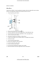
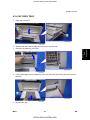
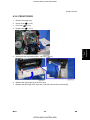
Move Exec
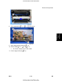
"Move Exec" (SP5873 1) moves application programs from the original SD card to another
SD card. The application programs are moved from Slot 2 to Slot 1.
1.
Turn off the main power switch.
2.
Remove the SD card slot cover [A] (
3.
Insert the original SD card with the application in Slot 2 [B] (lower slot).
4.
Insert the SD card to receive the application in Slot 1 [C] (upper slot).
5.
Turn on the main power switch.
6.
Enter the SP mode and do SP5873 1 "Move Exec."
7.
Follow the messages on the operation panel to complete the procedure.
8.
Exit the SP mode.
9.
Turn off the main power switch.
x 1).
10. Remove the original SD card from Slot 2.
11. Leave the other SD card in Slot 1.
12. Turn on the main power switch.
13. Confirm that the application program runs normally.
14. Tell the customer to store the original SD card in a safe place.
SM
2-4
CÓPIA NÃO CONTROLADA
M047
CÓPIA NÃO CONTROLADA
Machine Installation
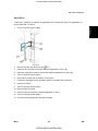
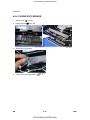
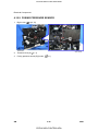
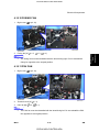
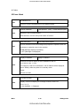
Undo Exec
"Undo Exec" (SP5873 2) restores an application to its original SD card. The application is
moved from Slot 1 to Slot 2.
Turn off the main power switch.
2.
Remove the SD card slot cover [A] (
3.
Insert the SD card that currently holds the application in Slot 1 [B].
4.
Insert the original SD card to receive the restored application in Slot 2 [C].
5.
Turn on the main power switch.
6.
Enter the SP mode and do SP5873 "Undo Exec."
7.
Follow the messages on the operation panel to complete the procedure.
8.
Exit the SP mode.
9.
Turn off the main power switch.
Installation
1.
x 1).
10. Remove both SD cards.
11. Insert the SD card with the restored application in Slot 1.
12. Turn on the main power switch.
13. Confirm that the application operates normally.
M047
2-5
CÓPIA NÃO CONTROLADA
SM
CÓPIA NÃO CONTROLADA
CÓPIA NÃO CONTROLADA
CÓPIA NÃO CONTROLADA
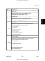
PREVENTIVE MAINTENANCE
R E V I S I O N H I S T O RY
P a ge
Date
A d de d /U pd at e d /N ew
None
CÓPIA NÃO CONTROLADA
CÓPIA NÃO CONTROLADA
CÓPIA NÃO CONTROLADA
CÓPIA NÃO CONTROLADA
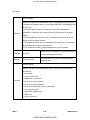
User Maintenance
3. PREVENTIVE MAINTENANCE
3.1 USER MAINTENANCE
The customer can do all PM items with the Maintenance Kit.
Meter-charge mode must be set to "disabled" (engine SP mode 5930).
Cross-reference: "Engine service mode" in the Appendices.
Preventive
Maintenance
The Operation panel shows "Replace Maintenance Kit" when the PM counter gets to 90K.
After the user replaces the fusing unit in the maintenance kit, the machine automatically
resets the PM counter.
Item
Quantity
Remarks
Fusing unit
1
Transfer roller
1
Paper feed roller
3
For standard and optional tray(s)
Friction pad
3
For standard and optional tray(s)
PSU Fan Filter
1
M047
3-1
CÓPIA NÃO CONTROLADA
SM
CÓPIA NÃO CONTROLADA
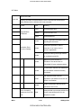
Service Maintenance
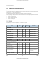
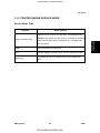
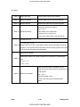
3.2 SERVICE MAINTENANCE
To enable the machine for maintenance by the service technician, the meter-charge mode
must be set to "1: Yes" with SP5930-001.
The table below shows the PM items serviced by the service technician.
After completing a PM procedure, reset the PM counter for the replaced part with SP7-804.
7-804-2: Transfer roller
7-804-3: Paper feed roller
7-804-4: Fusing unit.
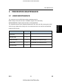
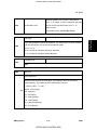
3.2.1 MAIN
Symbol keys: C: Clean/ R: Replace/ L: Lubricate/ I: Inspect
Item
90K
EM
Quantity
Remarks
Paper Feed Roller
R
C
1
Clean with water
Friction Pad
R
C
1
Clean with water
Registration Roller
C
C
1
Clean with water
Bottom Plate Pad
C
C
1
Clean with water
Paper Feed
Around the Drum
Transfer Roller
R
1
Hot Roller
R
1
Pressure Roller
R
1
Hot Roller Strippers
R
5
Fusing Thermistor
R
Bushings - Hot Roller
R
Fusing Unit and Paper Exit
SM
C
1
Clean with alcohol if
necessary.
2
3-2
CÓPIA NÃO CONTROLADA
M047
CÓPIA NÃO CONTROLADA
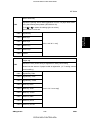
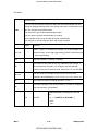
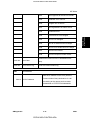
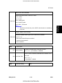
Service Maintenance
Item
Bushings - Pressure Roller
Fusing Entrance and Exit
Guide Plates
Fusing Unit
90K
EM
Quantity
R
2
C
1 each
R
1
R
1
Remarks
Clean with water or
alcohol
PSU Fan Filter
Preventive
Maintenance
Other
3.2.2 PAPER FEED UNIT (OPTION)
Symbol keys: C: Clean/ R: Replace/ L: Lubricate/ I: Inspect
Item
90K
EM
Quantity
Remarks
Paper Feed Roller
R
C
1
Clean with water
Friction Pad
R
C
1
Clean with water
Bottom Plate Pad
C
C
1
Clean with water
Paper Feed
M047
3-3
CÓPIA NÃO CONTROLADA
SM
CÓPIA NÃO CONTROLADA
CÓPIA NÃO CONTROLADA
CÓPIA NÃO CONTROLADA
REPLACEMENT AND ADJUSTMENT
R E V I S I O N H I S T O RY
P a ge
Date
A d de d /U pd at e d /N ew
None
CÓPIA NÃO CONTROLADA
CÓPIA NÃO CONTROLADA
CÓPIA NÃO CONTROLADA
CÓPIA NÃO CONTROLADA
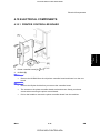
General
4. REPLACEMENT AND ADJUSTMENT
4.1 GENERAL
Turn off the main power switch and unplug the machine before attempting any of
the procedures in this section.
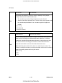
4.1.1 PRECAUTIONS ON DISASSEMBLY
Use extreme caution when removing and replacing components. The cables in the
machine are located very close to moving parts; proper routing is a must.
procedure must be restored as close as possible to their original positions. Before
removing any component from the machine, note any cable routings that may be affected.
Before servicing the machine:
1.
Verify that documents are not stored in memory.
2.
Remove the toner cartridge before you remove parts.
3.
Unplug the power cord.
4.
Work on a flat and clean surface.
5.
Replace with authorized components only.
6.
Do not force plastic material components.
Make sure all components are returned to their original positions.
Laser unit
1.
Do not loosen or adjust the screws securing the LD drive board on the LD unit. Doing
so will throw the LD unit out of adjustment.
2.
Do not adjust the variable resistors on the LD unit, as these are permanently adjusted
at the factory. If replacement of the LD drive board is necessary, replace the entire LD
unit.
3.
Keep the polygon mirror and toroidal lens free of dust. Laser performance is very
sensitive to dust on these components.
4.
Do not touch the shield glass or the surface of the polygon mirror with bare hands.
5.
Do not adjust the Laser Synchronization detector on the LD unit, as these are
permanently adjusted at the factory. If the position of the Laser Synchronization
detector has changed from the factory set position, SC 322 will be shown.
M047
4-1
CÓPIA NÃO CONTROLADA
SM
Replacement
and
Adjustment
After components have been removed, any cables that have been displaced during the
CÓPIA NÃO CONTROLADA
General
Transfer Roller
1.
Never touch the surface of the transfer roller with bare hands.
2.
Be careful not to scratch the transfer roller, as the surface is easily damaged.
Fusing
1.
After installing the fusing thermistor, make sure that it is in contact with the hot roller
and that the roller can rotate freely.
2.
Be careful to avoid damage to the hot roller stripper pawls and their tension springs.
3.
Do not touch the fusing lamp and rollers with bare hands.
4.
Make sure that the fusing lamp is positioned correctly and that it does not touch the
inner surface of the hot roller.
Paper Feed
1.
Do not touch the surface of paper feed rollers.
2.
To avoid misfeeds, the side and end fences in each paper tray must be positioned
correctly so as to align with loaded paper size.
4.1.2 RELEASING PLASTIC LATCHES
Many of the parts are held in place with plastic latches. The latches break easily, so release
them carefully.
To remove such parts, press the hook end of the latch away from the part to which it is
latched.
SM
4-2
CÓPIA NÃO CONTROLADA
M047
CÓPIA NÃO CONTROLADA
General
4.1.3 AFTER SERVICING THE MACHINE
Make sure all parts that require grounding are properly grounded.
2.
Make sure the interlock switch is functioning.
3.
Do not leave unused solder or parts inside the machine.
4.
Do not leave any tools inside the machine.
5.
Make sure all wires are properly connected and routed.
6.
Make sure wires are not jammed between parts of the machine.
Replacement
and
Adjustment
1.
M047
4-3
CÓPIA NÃO CONTROLADA
SM
CÓPIA NÃO CONTROLADA
Special Tools
4.2 SPECIAL TOOLS
Part
Number
Description
Q’ty
B6455010
SD Card
1
B6456705
SD Card Adapter
1
B6456830
USB Reader/Writer
1
A0069104
SM
Remarks
Used in common with other
printers.
Used in common with other
printers.
Used in common with other
printers.
Used for LD Unit positioning. Used
Scanner Positioning Pin
1
(4 pieces/set)
in common with the model K-P
series and other models.
4-4
CÓPIA NÃO CONTROLADA
M047
CÓPIA NÃO CONTROLADA
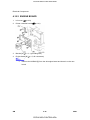
Exterior Covers
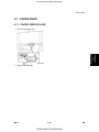
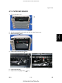
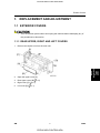
4.3 EXTERIOR COVERS
1.
Press the button [A], and then open the front door [B].
2.
Operation panel [A] (
M047
x 1, hooks [B],
Replacement
and
Adjustment
4.3.1 OPERATION PANEL
x 1)
4-5
CÓPIA NÃO CONTROLADA
SM
CÓPIA NÃO CONTROLADA
Exterior Covers
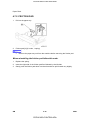
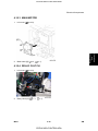
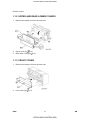
4.3.2 REAR COVER
1.
Rear cover [A]
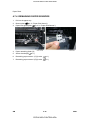
4.3.3 UPPER COVER
1.
Remove the AIO.
2.
Rear cover (
3.
Operation panel (
4.
Upper cover [A] (
SM
p.4-6)
p.4-5)
x 3)
4-6
CÓPIA NÃO CONTROLADA
M047
CÓPIA NÃO CONTROLADA
Exterior Covers
4.3.4 BY-PASS TRAY
Open the front door.
2.
Release the both rails [A] (right and left) on the by-pass tray.
3.
Close the by-pass tray cover [B].
4.
Lift the right edge of the by-pass tray cover [A], and then pull the by-pass tray cover to
Replacement
and
Adjustment
1.
the front.
5.
By-pass tray [A].
M047
4-7
CÓPIA NÃO CONTROLADA
SM
CÓPIA NÃO CONTROLADA
Exterior Covers
4.3.5 LEFT COVER
To remove the left cover, separate the machine from the optional paper feed unit
first.
1.
Upper cover (
p.4-6)
2.
Left cover [A] (
x 2)
SM
[1]: First release the rear left part of the left cover.
[2]: Pull down the left cover
[3]: Then remove it.
4-8
CÓPIA NÃO CONTROLADA
M047
CÓPIA NÃO CONTROLADA
Exterior Covers
4.3.6 FRONT DOOR
1.
Remove the paper tray.
2.
Upper cover (
3.
Left cover (
4.
By-pass tray (
5.
Disconnect two connectors (CN7, CN17) [A] (
6.
Release the right hinge [A] of the front door.
7.
Release the left hinge of the front door, and then remove the front door [B].
M047
p.4-6)
p.4-8)
Replacement
and
Adjustment
p.4-7)
x 3).
4-9
CÓPIA NÃO CONTROLADA
SM
CÓPIA NÃO CONTROLADA
Exterior Covers
4.3.7 RIGHT COVER
To remove the right cover, separate the machine from the optional paper feed unit
first.
p.4-6)
1.
Upper cover (
2.
Left cover (
3.
By-pass tray (
4.
Front door (
5.
Lift the right cover [A], and then pull the top edge of the right cover slightly (
p.4-8)
p.4-7)
p.4-9)
x 1, 3
tabs)
6.
Slide the right cover to the front with pulling down the right cover (4 tabs).
The fan cover [B] falls after detaching the right cover form the machine. It is
because that the fan cover is held only by the right cover.
SM
4-10
CÓPIA NÃO CONTROLADA
M047
CÓPIA NÃO CONTROLADA
Exterior Covers
Tab Locations on the Right Cover
Replacement
and
Adjustment
There are seven tabs on the right cover. Each arrow shows the direction of the tab.
M047
4-11
CÓPIA NÃO CONTROLADA
SM
CÓPIA NÃO CONTROLADA
Laser Unit
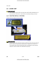
4.4 LASER UNIT
Turn off the main power switch and unplug the machine before attempting any of
the procedures in this section. Laser beams can seriously damage your eyes.
4.4.1 CAUTION DECAL LOCATION
Caution decals are attached as shown below.
Be sure to turn off the main power switch and disconnect the power plug from the
power outlet before beginning any disassembly or adjustment of the laser unit.
This machine uses a class IIIb laser beam with a wavelength of 785 nm and an
output of 6.2 mW. The laser can cause serious eye injury.
SM
4-12
CÓPIA NÃO CONTROLADA
M047
CÓPIA NÃO CONTROLADA
Laser Unit
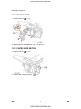
4.4.2 POLYGON MIRROR MOTOR
Turn off the main switch and unplug the machine before attempting any of the
procedures in this section. Laser beams can seriously damage your eyes.
Upper cover (
2.
Polygon mirror cover [A] (
x 2, tape [B] x 1,
3.
Polygon mirror motor [A] (
x 4,
M047
Replacement
and
Adjustment
p.4-6)
1.
x 2)
x 1)
Do not touch the surface of the mirror with bare hands.
4-13
CÓPIA NÃO CONTROLADA
SM
CÓPIA NÃO CONTROLADA
Laser Unit
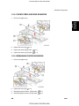
4.4.3 LASER UNIT
1.
Open the front door.
2.
Operation panel (
3.
Upper cover (
4.
Left cover (
5.
Disconnect the two harness (
6.
Remove the ground cable (
7.
Laser unit [A] (
SM
p.4-5)
p.4-6)
p.4-8)
x 1) at the left side.
x 1).
x 3, tape [B] x 1,
x 2)
4-14
CÓPIA NÃO CONTROLADA
M047
CÓPIA NÃO CONTROLADA
Laser Unit
When reinstalling the laser unit
Use the scanner positioning pins (P/N: A0069104) to reinstall the unit.
M047
4-15
CÓPIA NÃO CONTROLADA
Replacement
and
Adjustment
Set the positioning pins [A] as shown above. Then secure the laser unit.
SM
CÓPIA NÃO CONTROLADA
Laser Unit
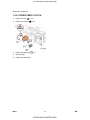
4.4.4 LASER DIODE UNIT
1.
Laser Unit (
p.4-14)
2.
Spring [A]
3.
LD unit holders [B] (x 2)
4.
Loosen the screw [C].
5.
Nut [D]
6.
LD Unit [E] (
x 1)
Do not remove the screws that secure the LD board.
Do not touch any variable resistors on the LD board.
When installing the LD Unit:
Tighten the screw [C] until the unpainted portion of the screw [a] is not visible.
After installing the LD unit, check the test pattern for the final adjustment (see the following
procedure).
SM
4-16
CÓPIA NÃO CONTROLADA
M047
CÓPIA NÃO CONTROLADA
Laser Unit
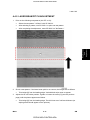
4.4.5 LASER BEAM PITCH ADJUSTMENT
Print out the following test patterns (A4 LEF or A3):
Select the test pattern "10.Stitch" with SP 5902-3.
After selecting a pattern, use SP 5902-1 to print one test pattern.
After completing the adjustment, reset SP 5902-3 to "NoPattern.”
Replacement
and
Adjustment
1.
2.
Check a test pattern. If the laser beam pitch is not correct, the images are as follows.
3.
Third stripe [A] from the leading edge: Vertical black strips seem to appear.
Adjust the LD unit holder position: Tighten or loosen the screw [C] (see the previous
page) until the printout appears as follows.
Third stripe [A] from the leading edge: The thin lines are of uniform thickness (no
striping effect should appear on the printout).
M047
4-17
CÓPIA NÃO CONTROLADA
SM
CÓPIA NÃO CONTROLADA
Image Transfer
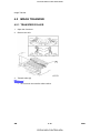
4.5 IMAGE TRANSFER
4.5.1 TRANSFER ROLLER
1.
Open the front door.
2.
Remove the AIO.
3.
Transfer roller [A]
SM
Do not touch the transfer roller surface.
4-18
CÓPIA NÃO CONTROLADA
M047
CÓPIA NÃO CONTROLADA
Image Transfer
4.5.2 TONER END SENSOR
Open the front door.
2.
Remove the AIO.
3.
Toner end sensor [A] (4 hooks,
Replacement
and
Adjustment
1.
M047
x 1)
4-19
CÓPIA NÃO CONTROLADA
SM
CÓPIA NÃO CONTROLADA
Fusing
4.6 FUSING
Allow time for the unit to cool before doing the following procedure.
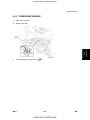
4.6.1 FUSING UNIT
1.
Rear cover [A]
2.
Fusing unit [B] (2 hooks [C])
SM
Lift both hooks before attempting to remove the fusing unit from the machine.
4-20
CÓPIA NÃO CONTROLADA
M047
CÓPIA NÃO CONTROLADA
Fusing
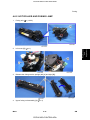
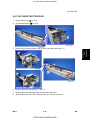
4.6.2 HOT ROLLER AND FUSING LAMP
Fusing unit (
p.4-20)
2.
Left cover [A] (
x 1)
3.
Release the fusing tension springs (left [A] and right [B]).
4.
Upper fusing unit assembly [A] (
M047
Replacement
and
Adjustment
1.
x 4)
4-21
CÓPIA NÃO CONTROLADA
SM
CÓPIA NÃO CONTROLADA
Fusing
Remove both springs before taking apart the fusing unit assembly. The reason
for this is to relieve pressure on the unit.
When reinstalling the fusing unit assembly, install both springs last. The
reason for this is to reset the springs back to their default position.
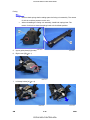
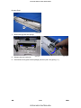
5.
Upper guide plate [A] (hooks)
6.
Right cover [B] (
7.
Left lamp holder [A] (
SM
x 1)
x 2)
4-22
CÓPIA NÃO CONTROLADA
M047
CÓPIA NÃO CONTROLADA
Fusing
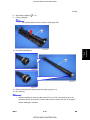
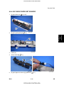
8.
Right lamp holder [A] (
9.
Fusing Lamp [B]
The colored cable must be at the hot roller gear side.
Replacement
and
Adjustment
x 2)
10. Hot roller assembly [A]
11. Remove the gear and bearings (left and right) (ring pin x 2)
12. Hot roller [A]
Before installing the new hot roller, peel off 3 cm (1 inch) from both ends of the
protective sheet on the new hot roller. Make sure to remove the rest of the paper
before starting the machine.
M047
4-23
CÓPIA NÃO CONTROLADA
SM
CÓPIA NÃO CONTROLADA
Fusing
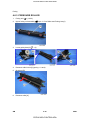
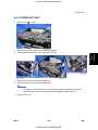
4.6.3 PRESSURE ROLLER
1.
Fusing unit (
2.
Upper fusing unit assembly (
3.
Lower guide plate [A] (
4.
Pressure roller levers [A] (spring x 1 each)
5.
Bushings [B]
6.
Pressure roller [A]
SM
p.4-20)
p.4-21 "Hot Roller and Fusing Lamp")
x 3)
4-24
CÓPIA NÃO CONTROLADA
M047
CÓPIA NÃO CONTROLADA
Fusing
When reassembling the fusing unit
When attaching the pressure roller lever to the lower fusing unit assembly, attach the spring
between the pressure roller lever and fusing unit first. If you try to attach the spring after
Replacement
and
Adjustment
attaching the pressure roller lever to the fusing unit, it is difficult to install the spring.
M047
4-25
CÓPIA NÃO CONTROLADA
SM
CÓPIA NÃO CONTROLADA
Fusing
4.6.4 THERMISTOR AND THERMOSTAT
Thermostat
1.
Upper fusing unit assembly (
2.
Thermostat [A] (
p.4-21 "Hot Roller and Fusing Lamp")
x 2)
Do not touch the thermostat with your hands.
Do not re-use a thermostat that is already opened. Safety is not guaranteed if you
do this.
Thermistor
1.
Upper fusing unit assembly (
2.
Inner wire cover [A] (
x 1)
3.
Grounding plate [B] (
x 2, 1 wire)
SM
p.4-21 "Hot Roller and Fusing Lamp")
4-26
CÓPIA NÃO CONTROLADA
M047
CÓPIA NÃO CONTROLADA
Fusing
Remove two screws [A] of the fusing unit connector.
5.
Upper wire cover [A] on the top of the fusing upper unit assembly (
6.
Fusing unit connector [A] (
Replacement
and
Adjustment
4.
M047
x 2)
x 1, 2 hooks)
4-27
CÓPIA NÃO CONTROLADA
SM
CÓPIA NÃO CONTROLADA
Fusing
7.
Thermistor [A] (
x 1, 1 harness)
When removing the thermistor, remove the entire unit first and then separate it into
two parts.
4.6.5 HOT ROLLER STRIPPERS
1.
Hot roller (
2.
Hot roller strippers [A] (1 spring each [B])
SM
p.4-21 "Hot Roller and Fusing Lamp")
4-28
CÓPIA NÃO CONTROLADA
M047
CÓPIA NÃO CONTROLADA
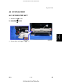
Paper Feed
4.7 PAPER FEED
4.7.1 PAPER FEED ROLLER
Pull out the paper tray.
2.
Paper feed roller [A]
Replacement
and
Adjustment
1.
M047
4-29
CÓPIA NÃO CONTROLADA
SM
CÓPIA NÃO CONTROLADA
Paper Feed
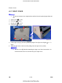
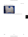
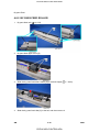
4.7.2 FRICTION PAD
1.
Pull out the paper tray.
2.
Friction pad [A] (2 hooks, 1 spring)
Remove the paper tray unit from the machine before removing the friction pad.
When reinstalling the friction pad follow this order
1.
Replace the spring.
2.
Insert the right side of the friction pad first followed by the left side.
3.
Gently push the friction pad down into the slot and then pull forward very slightly.
SM
4-30
CÓPIA NÃO CONTROLADA
M047
CÓPIA NÃO CONTROLADA
Paper Feed
4.7.3 PAPER END SENSOR
1.
Pull out the paper tray.
2.
Set the machine [A] on the table with the rear side facing down.
3.
Bottom plate [B] (
4.
Paper feed guide plate [A] (
5.
Paper end feeler [A]
6.
Paper end sensor [B] (hooks,
M047
Replacement
and
Adjustment
x 4)
x 2)
x 1)
4-31
CÓPIA NÃO CONTROLADA
SM
CÓPIA NÃO CONTROLADA
Paper Feed
4.7.4 REMAINING PAPER SENSORS
1.
Pull out the paper tray.
2.
Bottom plate (
3.
Paper feed guide plate (
4.
Paper remaining feeler [A]
5.
Sensor bracket [B] (
6.
Remaining paper sensor 1 [C] (hooks,
x 1)
7.
Remaining paper sensor 2 [D] (hooks,
x 1)
SM
p.4-31 "Paper End Sensor")
p.4-31 "Paper End Sensor")
x 1)
4-32
CÓPIA NÃO CONTROLADA
M047
CÓPIA NÃO CONTROLADA
By-pass Feed
4.8 BY-PASS FEED
4.8.1 BY-PASS FEED UNIT
Upper cover (
p.4-6)
2.
Left Cover (
p.4-8)
3.
Front door (
p.4-9)
4.
By-pass feed unit [A] (
Replacement
and
Adjustment
1.
M047
x 4,
x 1)
4-33
CÓPIA NÃO CONTROLADA
SM
CÓPIA NÃO CONTROLADA
By-pass Feed
4.8.2 BY-PASS FEED ROLLER
1.
By-pass feed unit (
2.
By-pass feed upper cover [A].
3.
Slide the by-pass feed roller holders [A] to the both edges (
4.
Slide the by-pass feed roller [A] to the left, and then remove it.
SM
p.4-33)
4-34
CÓPIA NÃO CONTROLADA
x 1 each).
M047
CÓPIA NÃO CONTROLADA
By-pass Feed
4.8.3 BY-PASS FRICTION PAD
1.
By-pass feed unit (
2.
By-pass feed roller (
3.
Bushing [A] at the right edge of the by-pass feed roller shaft (Clip x 1)
4.
By-pass feed gear [A] (spring x 1, clip x 1)
5.
Bushing [B] at the left edge of the by-pass feed roller shaft
6.
Slide the by-pass feed roller shaft [C] to the left, and then remove it.
M047
p.4-33)
4-35
CÓPIA NÃO CONTROLADA
Replacement
and
Adjustment
p.4-34)
SM
CÓPIA NÃO CONTROLADA
By-pass Feed
7.
Bottom bar [A] with two springs
8.
Release the two hooks [A].
9.
Press down the by-pass friction pad [B], and then pull it out (spring x 1).
SM
4-36
CÓPIA NÃO CONTROLADA
M047
CÓPIA NÃO CONTROLADA
By-pass Feed
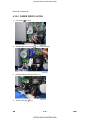
4.8.4 BY-PASS PAPER SET SENSOR
1.
By-pass feed unit (
p.4-33)
2.
By-pass guide plate [A] (
3.
Feeler [A]
4.
Sensor base [B] (
5.
By-pass paper set sensor [A] (hook x 3,
Replacement
and
Adjustment
x 3)
M047
x 1)
x 1)
4-37
CÓPIA NÃO CONTROLADA
SM
CÓPIA NÃO CONTROLADA
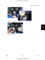
Paper Exit
4.9 PAPER EXIT
4.9.1 PAPER EXIT SENSOR
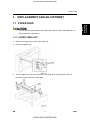
1.
Upper cover (
p.4-6)
2.
Paper exit sensor [A] (hooks,
x 1)
4.9.2 OVERFLOW SENSOR
1.
Upper cover (
2.
Overflow sensor [A] (hooks,
SM
p.4-6)
x 1)
4-38
CÓPIA NÃO CONTROLADA
M047
CÓPIA NÃO CONTROLADA
Paper Exit
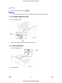
4.9.3 PAPER EXIT UNIT
Upper cover (
2.
Disconnect two connectors and release four clamps.
3.
Take aside the harnesses on the paper exit unit [A].
4.
Remove four screws on the paper exit unit.
5.
Remove the gear [A] (hook) and bushing [B].
p.4-6)
Replacement
and
Adjustment
1.
This gear is engaged with other drive gears through the timing belt. Check if
the timing belt is correctly installed after installing the paper exit unit.
6.
Paper exit unit [C]
M047
4-39
CÓPIA NÃO CONTROLADA
SM
CÓPIA NÃO CONTROLADA
Paper Exit
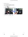
4.9.4 FUSING EXIT SENSOR
1.
Upper cover (
2.
Paper exit unit (
3.
Sensor box [A] (hooks)
4.
Fusing exit sensor [A] (hooks,
SM
p.4-6)
p.4-39)
x 1)
4-40
CÓPIA NÃO CONTROLADA
M047
CÓPIA NÃO CONTROLADA
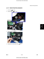
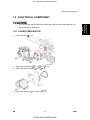
Electrical Components
4.10 ELECTRICAL COMPONENTS
Replacement
and
Adjustment
4.10.1 PRINTER CONTROLLER BOARD
1.
Printer controller board [A] (
2.
NVRAM [B]
x 2)
Remove the NVRAM from the old printer controller board and insert it on the new
board.
Remove the Duplex Unit before you remove the controller board.
The screws on the printer controller board are hand screws. Gently turn these
screws when removing the printer control board.
M047
Pull on the handle to remove the printer controller board from the machine.
4-41
CÓPIA NÃO CONTROLADA
SM
CÓPIA NÃO CONTROLADA
Electrical Components
4.10.2 ENGINE BOARD
1.
Left cover (
2.
Printer controller board (
3.
Bracket [A] (
4.
Engine board [B] (
p.4-8)
p.4-41)
x 2, 1 grounding wire)
x 5, all connectors)
Remove the NVRAM [C] from the old engine board and insert it on the new
board.
SM
4-42
CÓPIA NÃO CONTROLADA
M047
CÓPIA NÃO CONTROLADA
Electrical Components
4.10.3 MAIN MOTOR
Left cover (
p.4-8)
2.
Main motor [A] (
x 4,
Replacement
and
Adjustment
1.
x 1)
4.10.4 RELAY CLUTCH
1.
Left cover (
2.
Relay clutch [A] (
M047
p.4-8)
x 1,
x 1)
4-43
CÓPIA NÃO CONTROLADA
SM
CÓPIA NÃO CONTROLADA
Electrical Components
4.10.5 PAPER FEED CLUTCH
1.
Left cover (
2.
Release the harness [A] (
3.
Harness guide [A] (Rivet screw x 1)
4.
Clutch cover [A] (
SM
p.4-8)
x 5, all connectors)
x 1)
4-44
CÓPIA NÃO CONTROLADA
M047
CÓPIA NÃO CONTROLADA
Electrical Components
Clutch holder [A] (
6.
Paper feed clutch [A]
x 1)
Replacement
and
Adjustment
5.
M047
4-45
CÓPIA NÃO CONTROLADA
SM
CÓPIA NÃO CONTROLADA
Electrical Components
4.10.6 REGISTRATION CLUTCH
1.
Left cover (
2.
Main motor (
3.
Harness guide (
4.
Registration clutch [A] (
SM
p.4-8)
p.4-43)
p.4-44 "Paper Feed Clutch")
x 1,
x 1)
4-46
CÓPIA NÃO CONTROLADA
M047
CÓPIA NÃO CONTROLADA
Electrical Components
4.10.7 REGISTRATION SENSOR
1.
Left cover (
p.4-8)
2.
Harness guide (
3.
Sensor holder [A] (
4.
Registration sensor [A] (hooks,
Replacement
and
Adjustment
p.4-44)
M047
x 1)
x 1)
4-47
CÓPIA NÃO CONTROLADA
SM
CÓPIA NÃO CONTROLADA
Electrical Components
4.10.8 POWER SUPPLY BOARD AND HIGH VOLTAGE SUPPLY
BOARD
1.
Left cover (
2.
Fusing unit (
3.
PSU cover [A] (
4.
Remove the two screws [A] at the left of the machine.
5.
Disconnect three cables (pointed by arrow mark).
p.4-8)
p.4-20)
x 2)
Disconnect the cable [B] from the rear of the machine.
6.
Main switch link [C] (
7.
Ground cable [D] (
SM
x 1)
x 1: washer screw)
4-48
CÓPIA NÃO CONTROLADA
M047
CÓPIA NÃO CONTROLADA
Electrical Components
8.
PSU assembly [A] (
9.
High voltage supply board [A] (
x 3, all connectors)
Replacement
and
Adjustment
x 3,
10. Choke coil [B] (
x 2,
x 1)
The choke coil [B] is only for EU model.
11. Power supply board [C] (
M047
x 2,
x 4)
x 5)
4-49
CÓPIA NÃO CONTROLADA
SM
CÓPIA NÃO CONTROLADA
Electrical Components
4.10.9 FUSING PRESSURE SENSOR
1.
Right cover (
2.
Terminal cover [A] (
3.
Fusing pressure sensor [B] (hooks,
SM
p.4-10)
x 1)
x 1)
4-50
CÓPIA NÃO CONTROLADA
M047
CÓPIA NÃO CONTROLADA
Electrical Components
4.10.10 FUSING FAN
Right cover (
2.
Fusing fan [A] (
p.4-10)
x 2,
x 2,
x1)
The fusing fan must be reinstalled with the decal facing right. Do not reinstall the
fusing fan opposite to the original position.
4.10.11 PSU FAN
1.
Right cover (
2.
Terminal cover [A] (
3.
PSU fan [B] (
p.4-10)
x 2,
x 1)
x 1)
The PSU fan must be reinstalled with the decal facing left. Do not reinstall the PSU
fan opposite to the original position.
M047
4-51
CÓPIA NÃO CONTROLADA
SM
Replacement
and
Adjustment
1.
CÓPIA NÃO CONTROLADA
Image Adjustment
4.11 IMAGE ADJUSTMENT
4.11.1 REGISTRATION ADJUSTMENT
The registration is adjusted using the user mode; "Maintenance-Registration.” For details,
see the Printer Reference operation manual.
4.11.2 PARALLELOGRAM IMAGE ADJUSTMENT
Use the scanner positioning pin (P/N: A0069104) for the adjustment.
Do the following procedure if a parallelogram is printed while adjusting the printing
registration using a trimming pattern.
SM
4-52
CÓPIA NÃO CONTROLADA
M047
CÓPIA NÃO CONTROLADA
Replacement
and
Adjustment
Image Adjustment
p.4-6)
1.
Remove the upper cover (
2.
Put a positioning pin in one of the holes.
3.
Loosen four screws and move the laser unit.
4.
Tighten the laser unit.
5.
Print the trimming area pattern to check the image. If it is still the same, repeat steps 3
to 5.
M047
4-53
CÓPIA NÃO CONTROLADA
SM
CÓPIA NÃO CONTROLADA
CÓPIA NÃO CONTROLADA
CÓPIA NÃO CONTROLADA
SYSTEM MAINTENANCE
REFERENCE
R E V I S I O N H I S T O RY
P a ge
Date
A d de d /U pd at e d /N ew
None
CÓPIA NÃO CONTROLADA
CÓPIA NÃO CONTROLADA
CÓPIA NÃO CONTROLADA
CÓPIA NÃO CONTROLADA
Service Program Mode
5. SYSTEM MAINTENANCE REFERENCE
5.1 SERVICE PROGRAM MODE
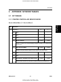
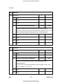
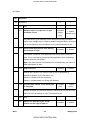
5.1.1 SP TABLES
See "Appendices" for the following information:
Printer Controller Service Mode Tables
Engine Mode Tables
Before accessing the service menu, do the following:
Confirm that there is no print data in the printer buffer (the Data In LED must not be
lit or blinking).
If there is some data in the buffer, wait until all data has been printed.
System
Maintenance
Reference
5.1.2 INPUTTING A VALUE OR SETTING FOR A SERVICE
PROGRAM
Enter the required program mode as explained above. The setting appearing on the display
is the current setting.
Select the required setting using the "Up/Down arrow" keys [A], then press the "OK" key [B].
The previous value remains if the "OK" key [B] is not pressed.
M047
5-1
CÓPIA NÃO CONTROLADA
SM
CÓPIA NÃO CONTROLADA
Service Program Mode
5.1.3 EXITING SERVICE MODE
Select "3. End" from the service mode main menu, then press the "OK" key.
SM
5-2
CÓPIA NÃO CONTROLADA
M047
CÓPIA NÃO CONTROLADA
Updating the Firmware
5.2 UPDATING THE FIRMWARE
Never turn off the machine while downloading the firmware.
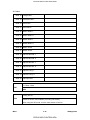
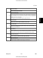
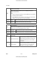
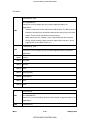
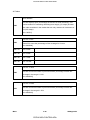
5.2.1 TYPE OF FIRMWARE
The table lists the firmware programs used by the machine. All programs can fit on one SD
card.
What It Updates
Engine
Printer engine control
Network DocBox
Document server firmware
Printer
Printer feature applications
System
Printer management
Network Support
Network application
Update Mode Err.
Displays if an error occurs.
Verify Data
Verifies that the update executed successfully.
M047
5-3
CÓPIA NÃO CONTROLADA
System
Maintenance
Reference
Program
SM
CÓPIA NÃO CONTROLADA
Updating the Firmware
5.2.2 PRECAUTIONS
Handling SD Cards
Observe these precautions when handling SD cards:
Always turn off the main power switch before you insert or remove an SD card. Data on
an SD card can be corrupted if you insert or remove an SD card while the main power
switch is on.
Never turn off the main power switch during downloading.
Keep SD cards in a safe location. Never store SD cards in locations where they will be
exposed to:
High temperature, high humidity
Direct sunlight
Strong vibrations
Magnetic fields generated by machines or electronic devices
Handle SD cards carefully to avoid dropping them, bending, scratching, etc.
Upload/Download
In this service manual, "upload" and "download" have these meanings:
Upload: Copying data from the printer to the SD card
Download: Copying data from the SD card to the printer
Network Connection
A print job sent to the machine during firmware update will interrupt the procedure. Before
you start the firmware update procedure tell the operator:
The machine must be disconnected from the network.
The machine cannot be used during firmware update.
SM
5-4
CÓPIA NÃO CONTROLADA
M047
CÓPIA NÃO CONTROLADA
Updating the Firmware
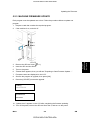
5.2.3 MACHINE FIRMWARE UPDATE
Each program must be updated one a time. Follow the procedure below to update one
program.
Prepare a card that contains the required program.
2.
If the machine is on, switch it off.
3.
Remove the SD card cover (
4.
Insert the SD card into Slot 2.
5.
Turn on the power.
6.
"Please Wait" appears, then you will see "Preparing to Start Firmware Update....”
7.
Firmware names are displayed on the LCD.
8.
Scroll to the program to upgrade, then press [OK].
9.
Press the [UPDATE] to start the upgrade.
System
Maintenance
Reference
1.
x 1).
Loading
*****************
Update done
xxxxxxxxx
10. "Update done" appears on the LCD after completing the firmware updating.
11. Turn off the power, remove the SD card from Slot 2, and turn on the power.
M047
5-5
CÓPIA NÃO CONTROLADA
SM
CÓPIA NÃO CONTROLADA
Updating the Firmware
-orIf you intend to update another program, leave the SD card in Slot 2 and turn off and
on the power.
The firmware has not updated successfully if the "Update done" message
does not appear. If this occurs, turn the machine power off/on and repeat the
procedure.
SM
5-6
CÓPIA NÃO CONTROLADA
M047
CÓPIA NÃO CONTROLADA
Updating the Firmware
5.2.4 ERROR RECOVERY
Controller
If an error occurs during updating the controller firmware, use the following procedure. This
procedure will force the controller to boot from the firmware SD card.
Prepare an SD card with the required controller firmware version.
2.
Turn off the machine and remove the controller.
3.
Change the DIP Switch 1 [A] - No.1 setting to "OFF.”
4.
Put back the controller
5.
Insert the SD card into the SD slot 2 (lower) on the controller.
6.
Turn on the machine. The machine automatically starts to download the software.
7.
When downloading is finished, "Updated" is displayed.
8.
Turn off the machine, then remove the card.
9.
Reset the DIP Switch 2 - No.1 setting to "ON" and then put back the controller.
System
Maintenance
Reference
1.
You must perform steps 5 to 8 for all three firmware cards.
The default settings of the DIP Switches are as followed; "No.1: ON" and "No.
2 to 4: OFF.”
10. Turn on the machine, and print the service summary report.
M047
5-7
CÓPIA NÃO CONTROLADA
SM
CÓPIA NÃO CONTROLADA
Updating the Firmware
Engine
If a download attempt failed, try downloading the new firmware again using the normal
firmware download procedure described in "Machine Firmware Update.”
SM
5-8
CÓPIA NÃO CONTROLADA
M047
CÓPIA NÃO CONTROLADA
Power-On Self Tests
5.3 POWER-ON SELF TESTS
The controller tests the following devices at power-on. If an error is detected, an error code
is stored in the controller board.
CPU, ASIC and clock
Flash ROM
Resident and optional SDRAM
NIB
IEEE 802.11a/g, Gigabit Ethernet or IEEE1284 (if installed)
NVRAM
Optional HDD (if installed)
To check the error codes, use engine SP 7832.
System
Maintenance
Reference
Refer to "Controller Error" for details about the error codes.
M047
5-9
CÓPIA NÃO CONTROLADA
SM
CÓPIA NÃO CONTROLADA
Dip Switches
5.4 DIP SWITCHES
5.4.1 CONTROLLER BOARD
DIP Switch 1 (Bit 1) on the controller board is used for the error recovery after the firmware
updating procedure failed.
The default settings of the DIP Switches are as followed; "No.1: ON" and "No. 2 to
4: OFF .”
SM
5-10
CÓPIA NÃO CONTROLADA
M047
CÓPIA NÃO CONTROLADA
TROUBLESHOOTING
R E V I S I O N H I S T O RY
P a ge
Date
A d de d /U pd at e d /N ew
None
CÓPIA NÃO CONTROLADA
CÓPIA NÃO CONTROLADA
CÓPIA NÃO CONTROLADA
CÓPIA NÃO CONTROLADA
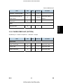
Service Call Conditions
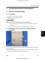
6. TROUBLESHOOTING
6.1 SERVICE CALL CONDITIONS
Troubleshooting
For "Service Call Conditions" information, see "Appendices.”
M047
6-1
CÓPIA NÃO CONTROLADA
SM
CÓPIA NÃO CONTROLADA
Electrical Component Defects
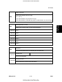
6.2 ELECTRICAL COMPONENT DEFECTS
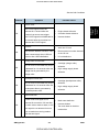
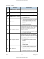
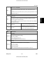
6.2.1 SENSORS
Component
CN
Condition
The Paper Jam indicator will light
Open
Paper Exit
Symptom
whenever a print is made.
CN14-20
The Paper Jam indicator lights even if
Shorted
there is no paper.
The paper overflow message is not
Open
Paper Overflow
displayed even when a paper overflow
condition exists.
CN4-30
The paper overflow message is
Shorted
displayed.
The Paper Jam indicator will light
Open
Fusing Exit
whenever a print is made.
CN5-25
The Paper Jam indicator lights even if
Shorted
there is no paper.
The Paper Jam indicator will light
Open
Registration
whenever a print is made.
CN14-35
The Paper Jam indicator lights even if
Shorted
there is no paper.
The Paper End indicator lights even if
Open
Remaining paper
sensor 1
paper is placed in the 1st paper tray.
CN14-26
The Paper End indicator does not light
Shorted
even if there is no paper in the 1st paper
tray.
SM
6-2
CÓPIA NÃO CONTROLADA
M047
CÓPIA NÃO CONTROLADA
Electrical Component Defects
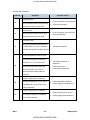
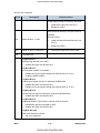
Component
Remaining paper
sensor 2
CN
Condition
Symptom
Open
The machine cannot determine the
Shorted
paper near-end condition properly.
CN14-29
The Paper End indicator lights even if
Open
Paper End
paper is placed in the 1st paper tray.
CN14-23
The Paper End indicator does not light
Shorted
even if there is no paper in the 1st paper
tray.
Toner near-end (toner end) is not
High
Toner End
detected.
CN14-33
Low
The add toner message is displayed.
Envelop mode is not selected even if the
Open
Fusing Pressure
Sensor
pressure lever at the fusing unit is set to
the envelop mode.
CN5-19
Envelop mode is always selected even if
Shorted
the pressure lever at the fusing unit is
M047
Troubleshooting
set to the other paper mode.
The CN numbers describe the connector number on the engine board.
6-3
CÓPIA NÃO CONTROLADA
SM
CÓPIA NÃO CONTROLADA
Electrical Component Defects
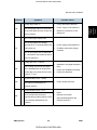
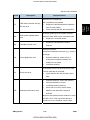
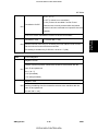
6.2.2 SWITCHES
Component
CN
Condition Symptom
The Front Cover Open message is not
Open
displayed even if the front cover is
opened.
Front Cover Safety
CN8-1/3
The Front Cover Open message is
Shorted
displayed even if the front cover is
closed.
The Cover Open (Rear Cover or Paper
Exit Cover) message is not displayed
Open
Rear Cover and
Paper Exit Cover
Safety
even if the rear cover or paper exit cover
CN4-1/5,
is opened.
CN4-3/T2
The Cover Open (Rear Cover or Paper
Shorted
Exit Cover) message is displayed even if
the rear cover or paper exit cover is
closed.
The CN numbers describe the connector number on the engine board (except for
the main switch).
SM
6-4
CÓPIA NÃO CONTROLADA
M047
CÓPIA NÃO CONTROLADA
Electrical Component Defects
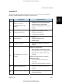
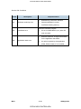
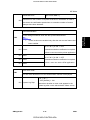
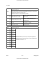
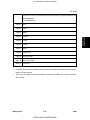
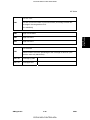
6.2.3 BLOWN FUSE CONDITIONS
Use a correct rating fuse for the fuse replacement. Never use a wrong rating fuse.
If do so, the machine may be damaged.
Rating
Symptom when turning on the main
Fuse
120 V
220 - 240 V
switch
Power Supply Board
FU1
15 A/125 V
8A/250V
Machine does not start.
FU2
5.0 A/125 V
3.15 A/250 V
Machine does not start.
FU3
4 A/125 V
4 A/250 V
Machine does not start.
FU4
5 A/125 V
5 A/250 V
Machine does not start.
"Please Wait" is displayed, but
FU5
6.3V/125V
6.3 A/250V
machine does not start or SC is
issued on the LCD.
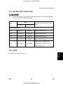
6.2.4 LEDS
M047
Troubleshooting
No LEDs are used for this model.
6-5
CÓPIA NÃO CONTROLADA
SM
CÓPIA NÃO CONTROLADA
CÓPIA NÃO CONTROLADA
CÓPIA NÃO CONTROLADA
ENERGY SAVING
R E V I S I O N H I S T O RY
P a ge
Date
A d de d /U pd at e d /N ew
None
CÓPIA NÃO CONTROLADA
CÓPIA NÃO CONTROLADA
CÓPIA NÃO CONTROLADA
CÓPIA NÃO CONTROLADA
Energy Save
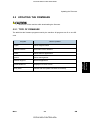
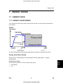
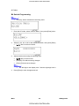
7. ENERGY SAVING
7.1 ENERGY SAVE
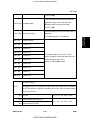
7.1.1 ENERGY SAVER MODES
The customer should use the energy saver mode correctly to save energy and protect the
environment.
The area shaded grey in this diagram represents the amount of energy that is saved.
Energy Saver Mode Setting
"Energy Saver" mode settings can be adjustable with User Mode (Menu > System >
Energy Saver).
Energy
Saving
Energy Saver On/Off
You can specify whether or not to switch Energy Saver.
On (Default)
Off
M047
7-1
CÓPIA NÃO CONTROLADA
SM
CÓPIA NÃO CONTROLADA
Energy Save
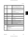
Energy Saver Timer
Specify time for entering the Energy Saver mode.
1 minute (Default)
5 minutes
15 minutes
30 minutes
45 minutes
60 minutes
Return to Standby Mode
The machine returns to standby mode from energy saver mode after 10 sec.
SM
7-2
CÓPIA NÃO CONTROLADA
M047
CÓPIA NÃO CONTROLADA
Paper Save
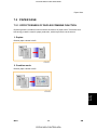
7.2 PAPER SAVE
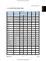
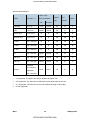
7.2.1 EFFECTIVENESS OF DUPLEX/COMBINE FUNCTION
Duplexing and the combine functions reduce the amount of paper used. This means that
less energy overall is used for paper production, which improves the environment.
1. Duplex:
Reduce paper volume in half!
2. Combine mode:
Energy
Saving
Reduce paper volume in half!
M047
7-3
CÓPIA NÃO CONTROLADA
SM
CÓPIA NÃO CONTROLADA
Paper Save
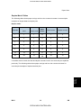
3. Duplex + Combine:
Using both features together can further reduce paper volume by 3/4!
To check the paper consumption, look at the total counter and the duplex counter.
The total counter counts all pages printed.
For one duplex page, the total counter goes up by 2.
For a duplex job of a three-page original, the total counter goes up by 3.
The duplex counter counts pages that have images on both sides.
For one duplex page, the duplex counter goes up by 1.
For a duplex job of a three-page original, the duplex counter will only increase by 1,
even though two sheets are used.
Recommendation
Please explain these features to the customers so they can reduce their paper usage.
SM
7-4
CÓPIA NÃO CONTROLADA
M047
CÓPIA NÃO CONTROLADA
Paper Save
Duplex Mode Tables
The following table shows paper savings and how the counters increase for some simple
examples of single-sided and duplex jobs
Duplex mode:
Simplex Sheet
Duplex
Paper
used
Sheets used
Saved
1
1
1
2
2
3
Originals
Total counter
Duplex counter
0
1
0
1
1
2
1
3
2
1
3
1
4
4
2
2
4
2
5
5
3
2
5
2
10
10
5
5
10
5
20
20
10
10
20
10
If combine mode is used, the total and duplex counters work in the same way as explained
previously. The following table shows paper savings and how the counters increase for
Energy
Saving
some simple examples of duplex/combine jobs.
M047
7-5
CÓPIA NÃO CONTROLADA
SM
CÓPIA NÃO CONTROLADA
Paper Save
2 in 1 mode:
Simplex Sheet
Duplex
Paper
used
Sheets used
Saved
1
1
1
2
2
3
Originals
SM
Total counter
Duplex counter
0
1
1
1
1
1
1
3
2
1
2
2
4
4
2
2
2
2
5
5
3
2
3
2
10
10
5
5
5
5
20
20
10
10
10
10
7-6
CÓPIA NÃO CONTROLADA
M047
CÓPIA NÃO CONTROLADA
Paper Save
Duplex + 2 in 1 mode:
Simplex Sheet
Duplex
Paper
used
Sheets used
Saved
1
1
1
2
2
3
Total counter
Duplex counter
0
1
1
1
1
1
1
3
1
2
2
2
4
4
1
3
2
2
5
5
2
3
3
3
6
6
2
4
3
3
7
7
2
5
4
4
8
8
2
6
4
4
9
9
3
6
5
5
10
10
3
7
5
5
11
11
3
8
6
6
12
12
3
9
6
6
Energy
Saving
Originals
M047
7-7
CÓPIA NÃO CONTROLADA
SM
CÓPIA NÃO CONTROLADA
CÓPIA NÃO CONTROLADA
CÓPIA NÃO CONTROLADA
M047
SERVICE MANUAL APPENDICES
CÓPIA NÃO CONTROLADA
CÓPIA NÃO CONTROLADA
CÓPIA NÃO CONTROLADA
CÓPIA NÃO CONTROLADA
M047 APPENDICES
TABLE OF CONTENTS
1. APPENDIX: SPECIFICATIONS ....................................................1-1 1.1 GENERAL SPECIFICATIONS ................................................................... 1-1 1.1.1 MAINFRAME .................................................................................... 1-1 1.1.2 CONTROLLER ................................................................................. 1-4 1.1.3 OPERATION PANEL LED SPECIFICATIONS ................................. 1-6 1.1.4 SUPPORTED PAPER SIZES ........................................................... 1-7 2. APPENDIX: TROUBLESHOOTING GUIDE .................................2-1 2.1 SERVICE CALL CONDITIONS .................................................................. 2-1 2.1.1 SUMMARY........................................................................................ 2-1 2.1.2 SC CODE DESCRIPTIONS .............................................................. 2-2 Engine SC ............................................................................................ 2-2 Controller SC ........................................................................................ 2-7 3. APPENDIX: SP MODE TABLES ..................................................3-1 3.1 SP TABLES ............................................................................................... 3-1 3.1.1 PRINTER CONTROLLER SERVICE MODE .................................... 3-1 Service Mode Menu ("1. Service Menu") .............................................. 3-1 Bit Switch Programming ....................................................................... 3-8 3.1.2 PRINTER ENGINE SERVICE MODE ............................................... 3-9 Service Mode Table ............................................................................. 3-9 SP1-xxx: Feed .................................................................................... 3-10 SP2-xxx: Drum ................................................................................... 3-16 SP3-xxx: Process ............................................................................... 3-18 SP5-xxx: Mode ................................................................................... 3-20 SP7-xxx: Data Log ............................................................................. 3-76 SP8XXX: Data Log 2 .......................................................................... 3-89 SM Appendix
i
CÓPIA NÃO CONTROLADA
M047
CÓPIA NÃO CONTROLADA
CÓPIA NÃO CONTROLADA
CÓPIA NÃO CONTROLADA
APPENDIX: SPECIFICATIONS
R E V I S I O N H I S T O RY
P a ge
Date
A d de d /U pd at e d /N ew
None
CÓPIA NÃO CONTROLADA
CÓPIA NÃO CONTROLADA
CÓPIA NÃO CONTROLADA
General Specifications
1. APPENDIX: SPECIFICATIONS
1.1 GENERAL SPECIFICATIONS
1.1.1 MAINFRAME
Configuration
Desktop
Paper size
DLT – A6 SEF
Laser beam scanning (Laser class: Class 1) & Electro
Technology
photographic printing
Dual component toner development AIO is used
Print Resolution
300/600/1200 dpi
Smoothing
Yes (on, off)
LEF A4 Mono 35 ppm
Continuous Print Speed
LT Mono 35 ppm
32 ppm from standard tray
Duplex Print Speed
(A4-LEF)
32 ppm from first optional paper tray
27 ppm from second optional paper tray
First Print Speed
6.8 seconds or less (A4/LT, LEF from standard tray)
Paper Tray
60-216 g/m2 (16-57 lb.)
By-pass tray
52-216 g/m2 (14-57 lb.)
Optional PFU
60-216 g/m2 (16-57 lb.)
Duplex
64-105 g/m2 (17-28 lb.)
Copy Paper Weight
Warm-up Time
SM Appendix
19 seconds or less from power on (23°C, 73°F)
12 seconds or less from energy saver mode
1-1
CÓPIA NÃO CONTROLADA
M047
Appendix:
Specifications
CÓPIA NÃO CONTROLADA
CÓPIA NÃO CONTROLADA
General Specifications
Standard tray
A3/DLT – A5
By-pass tray
A3/DLT – A6, Free size
Length: 148 - 432 mm (5.8" -
By-pass tray-Custom size 17"),
Width: 64 - 305 mm (2.5" - 12"),
paper
Com#10, C5, C6, DL. Monarch
Paper Input Size
Optional Envelope
Com#10, C5, C6, DL. Monarch
Feeder
Optional paper tray unit
Up to 2 units can be
A3/DLT – A5
installed.
Standard tray and
500 sheets (80 g/m2, 20 lb.)
Optional paper trays
Paper Input Capacity
100 sheets (80 g/m2, 20 lb.)
By-pass tray
Optional Envelope feeder 60 envelopes
Maximum paper input
1600 sheets
Output Capacity (Face
A3: 250 sheets
down)
A4 LEF: 500 sheets
Total Counter
Electric Counter
Environmental Standard
Energy Star Tier 2 or Ver. 1.1
North America: 120 V, 8.4 A or more, 60 Hz
Power Source
Europe: 220 - 240 V, 4.5 A or more, 50/60 Hz
Main Unit
NA
(including NIB)
Power Consumption
NA
M047
Full system
Maximum
870 W or less
880 W or less
Energy Saver
3.9 W or less
7.5 W or less
1-2
CÓPIA NÃO CONTROLADA
SM Appendix
General Specifications
Main Unit
EU
(including NIB)
Power Consumption
EU
Full system
Maximum
910 W or less
940 W or less
Energy Saver
3.9 W or less
7.5 W or less
Mainframe Only
Full System
Printing
67 dB or less
71 dB or less
Stand-by
40 dB or less
40 dB or less
Energy Saver
40 dB or less
40 dB or less
Noise Emission
Printing
55dB or less (Operating position)
Energy Saver
30dB or less (Operating position)
Sound Pressure Level
Weight
22.5 Kg. 49.6 lb. (including Paper Tray and AIO)
Excluding standard tray
Dimensions
(W x D x H)
Including standard tray
SM Appendix
478 x 410 x 404 (mm).
18.8 x 16.1 x 15.9 (inch)
478 x 437 x 404 (mm).
18.8 x 17.2x 15.9 (inch)
1-3
CÓPIA NÃO CONTROLADA
M047
Appendix:
Specifications
CÓPIA NÃO CONTROLADA
CÓPIA NÃO CONTROLADA
General Specifications
1.1.2 CONTROLLER
CPU
RM7035 466 MHz
Standard
PCL5e/ XL, IRIPS PS3/ PDF, RPCS
Option
IPDS
RPCS
300/600/1200 dpi
PCL6
600/1200 dpi
PCL5e
300/600 dpi
PS3
300/600/1200 dpi
PCL
45 fonts + 13 International fonts
PS
80 fonts (Type 2:24, Type 14:112)
Printer Languages
Resolution
Resident Fonts
Font Manager and 31 additional fonts for PCL to be loaded to the
PC, Euro currency ok.
Optional
OCR, Barcode
Windows
RPCS
2000/XP/Server2003/Vista/Server2008(32bit)
Windows XP/Server2003/Vista/Server2008(64bit)
Windows
Drivers
PCL6
2000/XP/Server2003/Vista/Server2008(32bit)
Windows XP/Server2003/Vista/Server2008(64bit)
Windows
PCL5e
2000/XP/Server2003/Vista/Server2008(32bit)
Windows XP/Server2003/Vista/Server2008(64bit)
M047
1-4
CÓPIA NÃO CONTROLADA
SM Appendix
General Specifications
Windows
PS3
2000/XP/Server2003/Vista/Server2008(32bit)
Windows XP/Server2003/Vista/Server2008(64bit)
Mac OS 8.6.0 or later, Mac OSX (10.1 or later)
NAND Flash: 128 MB
ROM
NOR Flash: 4MB
Standard
256 MB
Maximum
512 MB (with optional memory)
RAM
HDD
Option: 80 GB
Standard
USB 2.0, USB Host
10BASE-T/100BASE-TX
Interface
Optional
Bi-directional IEEE1284, Gigabit Ethernet,
IEEE802.11a/g
SD card. One SD card holds all programs
Firmware Update
RFU (Remote Firmware Update)
Network Protocol
TCP/IP (including IPP), IPX/SPX, SMBI, Apple Talk
NRS
Supported
DESS
Supported
The machine has a maximum memory capacity of 512 MB. You must install the
optional memory (256 MB) in the machine if you want to increase the machine
memory.
SM Appendix
1-5
CÓPIA NÃO CONTROLADA
M047
Appendix:
Specifications
CÓPIA NÃO CONTROLADA
CÓPIA NÃO CONTROLADA
General Specifications
1.1.3 OPERATION PANEL LED SPECIFICATIONS
LED
Power
Data In
Color
Blue
Blue
Appearance
Off
Power off or in Energy Saver mode
Flashing
Warming up
On
Power on and not in Energy Saver mode
Off
No data
Flashing
On
Suspend/
Resume
Blue
Red/
Yellow
Alert
M047
Meaning
Data being received or processed or the
printer is spooling
Data being received or processed; more
data coming
Off
Printer off-line
Flashing
Going off-line
On
Ready to print
Off
No messages or error conditions requiring
attention
Yellow
Flashing
Requiring service maintenance soon
Red
On
Printer requires service
1-6
CÓPIA NÃO CONTROLADA
SM Appendix
General Specifications
1.1.4 SUPPORTED PAPER SIZES
Paper Trays
Paper
Size (W x L)
Main Unit/Option
NA
EU/Asia
Bypass
Env.
Tray
Feeder
Duplex
A3
297 x 420 mm
Y#/Y
Y/Y
Y#
N
Y
B4
257 x 364 mm
Y#/Y#
Y#/Y#
Y#
N
Y
A4 SEF
210 x 297 mm
Y#/Y
Y/Y
Y#
N
Y
A4 LEF
297 x 210 mm
Y/Y
Y/Y
Y#
Y
Y
B5 SEF
182 x 257 mm
Y#/Y#
Y#/Y#
Y#
N
Y
B5 LEF
257 x 182 mm
Y#/Y#
Y#/Y#
Y#
N
Y
B6 SEF
128 x 182 mm
YC
YC
YC
N
N
A5 SEF
148 x 210 mm
Y#
Y#
Y#
N
Y
A5 LEF
210 x 148 mm
Y#/N
Y/N
Y#
N
Y
A6 SEF
105 x 148 mm
N
N
YC
N
N
Ledger
11 x 17"
Y/Y
Y#/Y
Y#
N
Y
Legal
8.5 x 14"
Y/Y
Y#/Y
Y#
N
Y
Letter SEF
8.5 x 11"
Y/Y
Y/Y
Y#
N
Y
Letter LEF
11 x 8.5"
Y/Y
Y/Y
Y#
N
Y
Half Letter SEF
5.5 x 8.5"
N
N
Y#
N
N
Half Letter LEF
8.5 x 5.5"
N
N
N
N
N
Executive SEF
7.25 x 10.5"
Y#/Y#
Y#/Y#
Y#
N
N
Executive LEF
10.5 x 7.25"
Y#/Y#
Y#/Y#
Y#
N
Y
F
8 x 13"
Y#/Y#
Y#/Y#
Y#
N
Y
SM Appendix
1-7
CÓPIA NÃO CONTROLADA
M047
Appendix:
Specifications
CÓPIA NÃO CONTROLADA
CÓPIA NÃO CONTROLADA
General Specifications
Paper Trays
Paper
Size (W x L)
Main Unit/Option
NA
EU/Asia
Bypass
Env.
Tray
Feeder
Duplex
Foolscap
8.5 x 13"
Y/Y#
Y#/Y#
Y#
N
Y
Folio
8.25 x 13”
Y#/Y#
Y#/Y#
Y#
N
Y
Com10 Env.
4.125 x 9.5"
N
N
Y#
Y#
N
Monarch Env.
3.875 x 7.5"
N
N
Y#
Y#
N
C6 Env.
114 x 162 mm
N
N
Y#
Y#
N
C5 Env.
162 x 229 mm
N
N
Y#
Y#
N
DL Env.
110 x 220 mm
N
N
Y#
Y#
N
8K
267 x 390 mm
Y#/Y#
Y#/Y#
Y#
N
Y
16K SEF
195 x 267 mm
Y#/Y#
Y#/Y#
Y#
N
Y
16K LEF
267 x 195 mm
Y#/Y#
Y#/Y#
Y#
N
Y
N/YC
N/YC
YC
N
N
Minimum:
Custom
90 x 148 mm
Maximum:
305 x 432 mm
Y: Supported. The paper size sensor detects the paper size.
Y#: Supported. The user has to select the correct paper size for the tray.
YC: Supported. The user has to enter the width and length of the paper.
N: Not supported.
M047
1-8
CÓPIA NÃO CONTROLADA
SM Appendix
CÓPIA NÃO CONTROLADA
APPENDIX:
TROUBLESHOOTING GUIDE
R E V I S I O N H I S T O RY
P a ge
Date
A d de d /U pd at e d /N ew
None
SM Appendix
1-1
CÓPIA NÃO CONTROLADA
M047
CÓPIA NÃO CONTROLADA
CÓPIA NÃO CONTROLADA
CÓPIA NÃO CONTROLADA
Service Call Conditions
2. APPENDIX: TROUBLESHOOTING GUIDE
Appendix:
Troubleshooting
Guide
2.1 SERVICE CALL CONDITIONS
2.1.1 SUMMARY
There are 2 levels of service call conditions.
Level
Definition
Reset Procedure
Only a service representative can
reset this SC. This will prevent
A
damage to the machine.
Enter engine SP mode 5810 and
press "#". When 'execute' is
displayed, press "#" again. Then
press 'Escape'. Then turn the main
You cannot use the machine.
power off/on.
The SC can be reset by turning the
B
operation switch off and on, if the
Set the main power off and on.
SC was caused by a sensor error.
SCs that are not shown on the
C
operation panel. They are internally
Logging only
logged.
If the problem is with electrical circuit boards, disconnect the connectors first. Then
reconnect the connectors before you replace the PCBs.
If the problem is with a motor lock, first examine the mechanical load. Then
replace motors or sensors.
SM Appendix
2-1
CÓPIA NÃO CONTROLADA
M047
CÓPIA NÃO CONTROLADA
Service Call Conditions
2.1.2 SC CODE DESCRIPTIONS
Engine SC
Code No.
202
B
Symptom
Possible Cause
Polygon motor error
The polygon motor does not reach its
operating speed within 10 seconds
after the polygon motor on signal, or
Polygon motor
the lock signal is not detected for
Polygon motor cable
Laser synchronization detector
more than a certain time during
operation.
1st laser synchronization error
board out of position
The laser synchronization detector
220
B
cannot detect the laser
board or cable defective
synchronization signal for more than
5 consecutive 100 ms intervals.
Laser synchronization detector
Laser synchronization mirror out
of position
LD unit defective
Engine board defective
Laser synchronization detector
2nd laser synchronization error
The 1st LD1 is already on, but the
laser synchronization detector
221
B
board out of position
cannot detect the laser
LD unit defective
synchronization signal from the 2nd
Engine board defective
LD for more than 5 consecutive 100
ms intervals.
M047
2-2
CÓPIA NÃO CONTROLADA
SM Appendix
CÓPIA NÃO CONTROLADA
Service Call Conditions
Code No.
Symptom
Possible Cause
FGATE error
230
B
detected for 1 second after the
Engine board defective
machine has sent a start trigger.
Controller board defective
The FGATE signal is still detected for
Appendix:
Troubleshooting
Guide
The FGATE signal cannot be
Harness broken
13 seconds after the machine has
detected the FGATE signal.
LD error
240
C
Worn-out LD unit
The machine detects LDB error a few
Disconnected or broken harness
times consecutively when LDB unit
of the LD unit
turns on after LDB initialization.
LD unit defective
Cartridge (charge roller)
Charge roller current leak
300
B
60% or more of the PWM duty output
defective
is detected for 0.2 seconds when the
charge bias is generated by the
High voltage supply board
defective
charge roller.
Development bias leak
330
B
Cartridge (development roller)
60% or more of the PWM duty output
defective
is detected for 0.2 seconds when the
development bias is generated by
High voltage supply board
defective
the development roller.
Main motor lock
520
B
A main motor lock signal is not
Main motor defective
detected for more than 700 ms after
Harness broken
the main motor starts to rotate, or the
lock signal is not detected for more
Too much load on the drive
mechanism
than a certain time during rotation
after the last signal.
SM Appendix
2-3
CÓPIA NÃO CONTROLADA
M047
CÓPIA NÃO CONTROLADA
Service Call Conditions
Code No.
Symptom
Possible Cause
Fusing fan error
530
B
The CPU detects the fusing fan lock
Poor connection of the fusing fan
Fusing fan defective
Poor connection of the PSU fan
PSU fan defective
Thermistor defective
Thermistor defective or
signal for more than 3 seconds.
PSU fan error
531
B
The CPU detects the PSU fan lock
signal for more than 3 seconds.
Thermistor error
The fusing temperature detected by
541
A
the thermistor is 0°C for 7 seconds
after the fusing relay has been turned
on.
Fusing temperature warm-up error
The fusing temperature does not
increase by 7°C for 10 seconds.
542
A
deformed
The fusing temperature does not
Fusing lamp open
reach more than 135°C for 24
Fusing thermostat open
A fusing temperature of over 235°C
Fusing thermistor defective
is detected for 0.5 seconds by the
Power supply board defective
Fusing control out of control
Power supply board defective
seconds after the main switch is
turned on.
Fusing overheat error: Software
543
A
fusing thermistor.
Fusing overheat error: Software
544
A
The machine detects an overheat
error of the hardware.
M047
2-4
CÓPIA NÃO CONTROLADA
SM Appendix
CÓPIA NÃO CONTROLADA
Service Call Conditions
545
A
Symptom
Possible Cause
Fusing lamp stays on
Fusing thermistor defective
The fusing lamp stays on more than
Power supply board defective
12 seconds after the main motor has
Defective connection of the
been turned off.
fusing unit
Zero cross signal malfunction
Zero cross signals are already
547
B
detected for 0.15 seconds before the
Power supply board defective
fusing relay-on.
Unstable main power supply
condition
Zero cross signals are not detected
for 3 seconds or the machine cannot
detect a frequency.
Fusing jam error: 3 counts
At the fusing exit sensor the paper
559
A
Obstacle in the paper transport
path
jam is detected late for three pulse
Fusing unit installed incorrectly
counts (lag error) when SP1913-001
Fusing unit defective
Engine board defective
Noise
Harness connection
is set to "1: Yes".
Communication error - GAVD
620
B
The engine board detects an
unknown device.
Communication error - PFU
Three consecutive errors are
622
B
detected during polling after the PFU
disconnected between the
is successfully detected by the
machine and PFU
machine.
SM Appendix
2-5
CÓPIA NÃO CONTROLADA
M047
Appendix:
Troubleshooting
Guide
Code No.
CÓPIA NÃO CONTROLADA
Service Call Conditions
Code No.
Symptom
Possible Cause
EEPROM error
The EEPROM error is detected at
669
B
EEPROM not installed or
incorrectly installed
reading the prefix of the EEPROM
EEPROM defective
Controller board defective
The controller does not send a ready
notification of image data
Controller board defective
address after power-on or recovery
from the energy saver mode.
PER-command error
The machine does not receive
687
B
PAPI-PER command for s10
seconds after PAPI-PES has been
issued.
Ready notification error of image
data transmission
688
B
Communication error
transmission after a sheet of paper
has stopped at the registration roller.
M047
2-6
CÓPIA NÃO CONTROLADA
SM Appendix
CÓPIA NÃO CONTROLADA
Service Call Conditions
Controller SC
The following table describes the controller error codes. These codes are displayed at
Code
Description
Engine to controller
641
communication error (no
answer).
670
819
820
Appendix:
Troubleshooting
Guide
power-on, or after the power-on self test, if an error occurs.
Required Action
Examine the connection between the
controller and the engine board.
Replace the engine board if the error is
frequent.
Engine response error
Kernal end error
Controller CPU error
Engine board installed incorrectly
Engine board defective
Controller board defective
HDD error
Software application error
RAM shortage
Replace the controller if the error is
frequent.
Replace the engine board.
ASIC for system control could not be
detected. After the PCI configuration, the
device ID for the ASIC could not be
833
checked.
Self-diagnostic error: Engine
Replace the mother board or check the
I/F ASIC
harness connection.
Could not initialize or read the bus
connection.
851
853
IEEE1394 interface error
Value of the SSCG register is incorrect.
Replace the controller if the error is
frequent.
Wireless LAN Error: Card Error
Wireless LAN card not inserted into the
1
wireless LAN board
SM Appendix
2-7
CÓPIA NÃO CONTROLADA
M047
CÓPIA NÃO CONTROLADA
Service Call Conditions
Code
854
855
856
Description
Wireless LAN Error: Card Error
2
Required Action
Wireless LAN card has been removed
Wireless LAN Error: Card Error
Wireless LAN card defective
3
Wireless card connection not tight
Wireless LAN card board defective
PCI connector loose
The USB driver can generate three types
Wireless LAN Error 4: Board
of errors: RX, CRC, and STALL errors.
857
Only the STALL error can generate this
USB I/F Error
SC code.
Defective controller board
A serious error occurs when data is encrypted
to update an encryption key with the HDD
858
HDD Encryption unit error 1
encryption unit. [Number] shows a suffix
number of SC code.
[0], [1], [30]: Replace the controller board.
[2]: Replace the NVRAM.
A serious error occurs when the HDD data is
encrypted to update an encryption key with the
HDD encryption unit. [Number] shows a suffix
number of SC code.
859
HDD Encryption unit error 2
[8]: Install the HDD correctly or initialize
the HDD.
[9]: Initialize the HDD.
[10]: Replace the HDD or replace the
controller board.
860
HDD start-up error
Turn off the machine and turn it back on.
Examine the connection between the
HDD and the controller.
M047
Replace the HDD if the error is frequent.
2-8
CÓPIA NÃO CONTROLADA
SM Appendix
CÓPIA NÃO CONTROLADA
Service Call Conditions
861
Description
HDD: Reboot error
863
HDD data unable to read
864
HDD data access error
865
HDD access error
866
SD card authentication error
867
SD card error
Required Action
Loose connection of HDD
Defective cables of HDD
Defective HDD
Defective controller
Replace the HDD if the error is frequent.
Appendix:
Troubleshooting
Guide
Code
SD-card data is corrupted.
Store correct data in the SD card.
The SD card is ejected from the slot.
Install the SD card.
-13 to -3 (sub-code): File system error
868
SD card access error
Format the SD card on your PC.
Replace the SD card.
Replace the controller.
Other number (sub-code): Device error
Turn off and on the machine.
Defective software program
Defective HDD
Incorrect path to the server
870
Address book error
Initialize the address book data
(SP5-846-050).
Initialize the HDD (SP5-832-001).
Replace the HDD.
Defective HDD
872
873
HDD mail data error
HDD mail transfer error
SM Appendix
Power failure during an access to the HDD
Initialize the HDD (SP5-832-001).
Replace the HDD.
Defective HDD
2-9
CÓPIA NÃO CONTROLADA
M047
CÓPIA NÃO CONTROLADA
Service Call Conditions
Code
Description
Required Action
Power failure during an access to the HDD
Initialize the HDD (SP5-832-001).
Replace the HDD.
Data Overwrite Security Unit (SD card) not
installed
874
Delete All error 1: HDD
Defective HDD
Install the Data Overwrite Security Unit
(D377).
875
Delete All error 2: Data area
876
Log Data Error
Replace the HDD.
The logical format for the HDD fails.
Log Data Error 1
Damaged log data file in the HDD
Initialize the HDD with SP5832-001.
Log Data Error 2
An encryption module not installed
Disable the log encryption setting with SP9730-004 ("0" is off.)
Install the DESS module.
Log Data Error 3
Invalid log encryption key due to defective NVRAM data
Initialize the HDD with SP5832-001.
Disable the log encryption setting with SP9730-004 ("0" is off.)
Log Data Error 4
Unusual log encryption function due to defective NVRAM data
Initialize the HDD with SP5832-004.
Log Data Error 5
Installed NVRAM or HDD which is used in another machine
Reinstall the previous NVRAM or HDD.
Initialize the HDD with SP5832-001.
Log Data Error 99
Other than the above causes
M047
Ask your supervisor.
2-10
CÓPIA NÃO CONTROLADA
SM Appendix
CÓPIA NÃO CONTROLADA
Service Call Conditions
Code
Description
Required Action
Defective SD card (M352)
SD card error
SD card (M352) not installed
new SD card (M352).
878
900
Replace the NVRAM and then install the
TPM system authentication
error
Controller counter error
Check and reinstall the SD card (M352).
Incorrect updating for the system firmware
Defective flash ROM on the controller board
Replace the controller board.
Replace the NVRAM if the error is
frequent.
Defective software
Unexpected hardware resource (e.g., memory
shortage)
920
Printer application error
Software defective; switch off/on, or
change the controller firmware if the
problem is not solved
Insufficient memory
A necessary font is not found in the SD card.
921
The SD card data is corrupted.
Printer font error
Check that the SD card has the correct
data.
990
Software performance error
Software defective; reboot the machine
Internal parameter incorrect
Insufficient working memory
When this SC occurs, the file name,
address, and data will be stored in
NVRAM.
Note the above data and the situation in which
this SC occurs. Then report the data and
conditions to your technical control center.
SM Appendix
2-11
CÓPIA NÃO CONTROLADA
M047
Appendix:
Troubleshooting
Guide
877
HDD Data Overwrite Security
CÓPIA NÃO CONTROLADA
Service Call Conditions
Code
991
Description
Software continuity error
Required Action
Software bug; reboot the machine
Internal parameter incorrect
Insufficient working memory
Defective software program
992
Undefined error
An error undetectable by any other SC
code occurred
998
Application start error
Software defective; change the firmware
for the application that failed
An option required by the application
(RAM, DIMM, board) is not installed
M047
2-12
CÓPIA NÃO CONTROLADA
SM Appendix
CÓPIA NÃO CONTROLADA
APPENDIX:
SP MODE TABLES
R E V I S I O N H I S T O RY
P a ge
Date
A d de d /U pd at e d /N ew
None
CÓPIA NÃO CONTROLADA
CÓPIA NÃO CONTROLADA
CÓPIA NÃO CONTROLADA
CÓPIA NÃO CONTROLADA
SP Tables
3. APPENDIX: SP MODE TABLES
3.1 SP TABLES
3.1.1 PRINTER CONTROLLER SERVICE MODE
1001
Appendix: SP
Mode Tables
Service Mode Menu ("1. Service Menu")
Bit Switch
001 Bit Switch 1
0
1
bit 0
DFU
-
-
bit 1
DFU
-
-
bit 2
DFU
-
-
bit 3
No I/O Timeout
0: Disable
1: Enable
Enable: The MFP I/O Timeout setting will have no effect. I/O Timeouts will
never occur.
bit 4
0: Disable
SD Card Save Mode
1: Enable
Enable: Print jobs will be saved to an SD Card in the GW SD slot.
bit 5
DFU
-
-
bit 6
DFU
-
-
bit 7
[RPCS,PCL]: Printable area frame border
0: Disable
1: Enable
Prints all RPCS and PCL jobs with a border around the printable area.
SM Appendix
3-1
CÓPIA NÃO CONTROLADA
M047
CÓPIA NÃO CONTROLADA
SP Tables
1001
Bit Switch
002 Bit Switch 2
0
1
bit 0
DFU
-
-
bit 1
DFU
-
-
bit 2
DFU
-
-
bit 3
[PCL5e/c,PS]: PDL Auto Switching
0: Enable
1: Disable
Disable: The MFPs ability to change the PDL processor mid-job.
Some host systems submit jobs that contain both PS and PCL5e/c. If Auto
PDL switching is disabled, these jobs will not be printed properly.
1001
bit 4
DFU
-
-
bit 5
DFU
-
-
bit 6
DFU
-
-
bit 7
DFU
-
-
0
1
Bit Switch
003 Bit Switch 3
bit 0
DFU
-
-
bit 1
DFU
-
-
bit 2
[PCL5e/c]: Legacy HP compatibility
0: Disable
1: Enable
Enable: Uses the same left margin as older HP models such as
HP4000/HP8000.
In other words, the left margin defined in the job (usually "<ESC>*r0A")
will be changed to "<ESC>*r1A"
M047
bit 3
DFU
-
-
bit 4
DFU
-
-
3-2
CÓPIA NÃO CONTROLADA
SM Appendix
CÓPIA NÃO CONTROLADA
SP Tables
DFU
-
-
bit 6
DFU
-
-
bit 7
DFU
-
-
Bit Switch
004 Bit Switch 4 DFU
bit 0
DFU
0
1
-
-
bit 1
DFU
-
-
bit 2
DFU
-
-
bit 3
IPDS
0: Disable
1: Enable
print-side
Appendix: SP
Mode Tables
1001
bit 5
reversal
If enabled, the simplex pages of IPDS jobs will be printed on the front
side because of printing on the back side of the page. This might
reduce printing speed.
bit 4
DFU
-
-
bit 5
DFU
-
-
bit 6
DFU
-
-
bit 7
DFU
-
-
SM Appendix
3-3
CÓPIA NÃO CONTROLADA
M047
CÓPIA NÃO CONTROLADA
SP Tables
1001
Bit Switch
005 Bit Switch 5
bit 0
DFU
bit 1
Multiple copies if a paper size or type
0
1
-
-
0: Disable
(Single
mismatch occurs
copy)
1: Enable
(Multiple copy)
If a paper size or type mismatch occurs during the printing of multiple
copies, only a single copy is output by default. Using this BitSw, the device
can be configured to print all copies even if a paper mismatch occurs.
bit 2
Prevent SDK applications from altering
0: Disable
the contents of a job.
1: Enable
If this BitSw is enabled, SDK applications will not be able to alter print
data. This is achieved by preventing SDK applications from accessing a
module called the "GPS Filter".
Note: The main purpose of this BitSw is for troubleshooting the effects of
SDK applications on data.
bit 3
0: Pattern3
[PS] PS Criteria
1: Pattern1
Change the number of PS criterion used by the PS interpreter to
determine whether a job is PS data or not.
Pattern3: includes most PS commands.
Pattern1: A small number of PS tags and headers
bit 4
Increase max number of the stored jobs
to 1000 jobs.
0: Disable
1: Enable
(100)
(1000)
Enable: Changes the maximum number of jobs that can be stored on the
HDD via Job Type settings to 1000. The default is 100.
bit 5
DFU
bit 6
Method for determining the image
rotation for the edge to bind on.
M047
3-4
CÓPIA NÃO CONTROLADA
-
-
0: Disable
1: Enable
SM Appendix
CÓPIA NÃO CONTROLADA
SP Tables
If enabled, the image rotation will be performed as they were in the
specifications of older models for the binding of pages of mixed orientation
jobs.
The old models are below:
- PCL: Pre-04A models
- PS/PDF/RPCS:Pre-05S models
Letterhead mode printing
0: Disable
1: Enable
(Duplex)
Routes all pages through the duplex unit.
If this is disabled, simplex pages or the last page of an odd-paged duplex
job, are not routed through the duplex unit. This could result in problems
with letterhead/pre-printed pages.
Only affects pages specified as Letterhead paper.
1001
Bit Switch
006 Bit Switch 6
bit 0
to 5
DFU
PDL Auto Detection timeout of jobs
submitted via USB or Parallel Port
(IEEE 1284).
bit 6
0
1
-
-
0: Disable
(Immediately)
1: Enable
(10
seconds)
To be used if PDL auto-detection fails. A failure of PDL autodetection
doesn't necessarily mean that the job can't be printed. This bit switch tells
the device whether to time-out immediately (default) upon failure or to wait
10 seconds.
bit 7
SM Appendix
DFU
-
3-5
CÓPIA NÃO CONTROLADA
-
M047
Appendix: SP
Mode Tables
bit 7
CÓPIA NÃO CONTROLADA
SP Tables
1001
Bit Switch
007 Bit Switch 7
Print path
0
1
0: Disable
1: Enable
If enabled, simplex pages (in mixed simplex/duplex PS/PCL5 jobs only)
bit 0
and the last page of an odd paged duplex job (PS, PCL5, PCL6), are
always routed through the duplex unit. Not having to switch paper paths
increases the print speed slightly.
bit 1
to 7
1001
DFU
-
-
-
-
Bit Switch
008 Bit Switch 8 DFU
Clear Setting
1003
Initializes settings in the System menu of the user
001 Init. System
mode.
003 Delete Program
DFU
Print Summary
1004
Service Summary
001
Touch [Execute] to print the printer summary sheets.
M047
3-6
CÓPIA NÃO CONTROLADA
SM Appendix
CÓPIA NÃO CONTROLADA
SP Tables
1005
Display Version.
Printer Version
Displays the version of the controller firmware.
Supply Display
Enables or disables the display for information on each consumable supply.
001 Development
002 PCU
003 Transfer
004 Int. Transfer
[0 or 1 / 1 / 1 /step]
0: OFF, 1: ON
005 Transfer Roller
006 Fuser
007 Fuser Oil
SM Appendix
3-7
CÓPIA NÃO CONTROLADA
M047
Appendix: SP
Mode Tables
1007
CÓPIA NÃO CONTROLADA
SP Tables
Bit Switch Programming
Currently, the bit switches are not being used.
1.
Enter the SP mode, select "Service Menu", then press [Enter] twice.
2.
Select #1, #2, #3, or #4 for the desired bit switch, then press [Enter].
3.
[ ] [ ]: Move to the next switch.
Adjust the bit switch using the following keys.
[ ] [ ]: Move to the next bit.
[Escape]: Exit without saving changes.
[Enter]: Exit and save changes.
4.
The left digit on the display is bit 7 and the right digit is bit 0.
Press [Enter] to save changes and exit.
M047
3-8
CÓPIA NÃO CONTROLADA
SM Appendix
CÓPIA NÃO CONTROLADA
SP Tables
3.1.2 PRINTER ENGINE SERVICE MODE
Service Mode Table
Notation
What it means
Example: [-9 to +9 / 3.0 / 0.1 mm step]. The setting can be
adjusted in the range ±9, value reset to +3.0 after an NVRAM
reset, and the value can be changed in 0.1 mm steps with
each key press.
Bold
Comments added for reference.
DFU
Denotes "Design or Factory Use". Do not change this value.
Japan only
SM Appendix
The feature or item is for Japan only. Do not change this
value.
3-9
CÓPIA NÃO CONTROLADA
M047
Appendix: SP
Mode Tables
[range / default / step]
CÓPIA NÃO CONTROLADA
SP Tables
SP1-xxx: Feed
Lead Edge Regist
Adjusts the printing leading edge registration for feeding from the trays and
1001
duplex tray using the trimming area pattern (SP5-902-003 No.9).
Push [ ] or [ ] to select the settings (plus or minus).
The specification is 4±2 mm
1001 1 BypassTray Plain
1001 2 BypassTray Thick
1001 3 BypassTray Thick2
1001 4 MainTray Plain
1001 5 MainTray Thick
[-40 to +40 / 0 / 1 mm]
1001 6 MainTray Thick2
1001 7 BankTray Plain
1001 8 BankTray Thick
1001 9 BankTray Thick2
1001 10 Duplex
M047
3-10
CÓPIA NÃO CONTROLADA
SM Appendix
CÓPIA NÃO CONTROLADA
SP Tables
Side to Side Reg
Adjusts the printing side-to-side registration from the 1st paper feed station
1002
using the trimming area pattern (SP2-902 No.12).
Push [ ] or [ ] to select the settings (plus or minus).
Specification: 0 ±2.0 mm.
Appendix: SP
Mode Tables
1002 1 BypassTray
1002 2 MainTray1
1002 3 MainTray2
[-40 to +40 / 0 / 1 mm]
1002 4 BankTray1
1002 5 BankTray2
1002 6 Duplex
Regist sag
1003
Adjusts the relay clutch timing at registration. Relay clutch timing
determines the amount of paper buckle at registration. (A "+" setting causes
more buckling.)
1003 1 BypassTray Plain
1003 2 BypassTray Thick
1003 3 BypassTray Thick2
1003 4 MainTray Plain
1003 5 MainTray Thick
[–8 to 8 / 0 / 1 mm step]
1003 6 MainTray Thick2
1003 7 BankTray Plain
1003 8 BankTray Thick
1003 9 BankTray Thick2
SM Appendix
3-11
CÓPIA NÃO CONTROLADA
M047
CÓPIA NÃO CONTROLADA
SP Tables
1003 10 Duplex
Fusing control
1104
0: Normal, 1: Phase control
Use phase control if the room lights flicker when the fusing lamp starts.
Defaults: North America – Normal (On/off control), Europe – Phase
Fusing Temp.
1105
Adjusts the fusing temperatures for printing and standby mode.
Plain
[150 to 200 / 170 / 5 deg.] DFU
1105 1
Adjusts the fusing temperature for printing on normal paper.
Thick2
[150 to 195 / 185 / 5 deg.] DFU
1105 2
Adjusts the fusing temperature for printing on thick 2 paper.
Standby Temp
[140 to 175 / 168 / 1 deg.] DFU
1105 3
Adjusts the fusing temperature for standby mode.
1106
Fusing Temp Disp
1106 1 Displays the current fusing temperature.
M047
3-12
CÓPIA NÃO CONTROLADA
SM Appendix
CÓPIA NÃO CONTROLADA
SP Tables
OP LoopBackCheck
1901
Displays the result of the optional loop back checking at power on.
Displays the error status for each option.
Summary
0: Normal, 1: Error
1901 1 bit 0: Bank (paper feed) unit error
Appendix: SP
Mode Tables
bit 1: Bin unit error (Not used)
bit 2: Duplex unit error
BankTray
[0 to 255 / 0 / 1 step.]
1901 2
Displays the error status for the optional paper feed unit.
0: Checking is correctly done.
7: X3FCL is not "ON".
1: D5 is not "High".
8: X3FCL is not "OFF".
2: D5 is not "Low".
9: X3MOTOR is not "ON".
3: X2FCL is not "ON".
10: X3 MOTOR is not "OFF".
4: X2FCL is not "OFF".
11: D4 is not "Low".
5: X2MOTOR is not "ON".
255: Loop back connector is not
6: X2 MOTOR is not "OFF".
connected.
Duplex
[0 to 255 / 0 / 1 step.]
Displays the error status for the optional duple unit.
1901 4 0: Checking is correctly done.
1: Serial number communication fails.
2: DPXSET is not "Low".
255: Loop back connector is not connected.
SM Appendix
3-13
CÓPIA NÃO CONTROLADA
M047
CÓPIA NÃO CONTROLADA
SP Tables
Curl Control
Curl Reduction
Thin paper has a tendency to jam or wrinkle, especially during duplex
printing. When this SP code is switched on:
1911
The machine ignores the fusing temperature set for SP1105.
When the machine is powered on or recovers from the low power mode
the machine requires about 20 sec. to warm up (this is longer than
normal).
[0 or 1 / 0 / -]
0: No (Normal)
1: Yes (Curl Control)
SC559 Detect
Fusing Jam SC Setting
This SP setting determines whether SC559 is issued after three paper late
jams occur in the fusing unit. After this SP code is turned on, a counter
monitors the number of paper late jams that occur in the fusing unit. After
the 3rd occurrence of a fusing jam, SC559 is issued and the machine
1913
cannot be used until the service technician releases the error.
Note: Switching the machine off/on does not reset this jam counter. The
counter is reset after the cause of the jam has been removed and a sheet of
paper successfully passes the fusing exit sensor.
[0 to 1 / 0 / 1]
0: No
1: Yes
M047
3-14
CÓPIA NÃO CONTROLADA
SM Appendix
CÓPIA NÃO CONTROLADA
SP Tables
1914
Nip Measure (Fusing Nip Width Measurement)
Measure Exe.
1914 001
-
-
Performs the nip width measurement. This is for by-pass tray and used OHP
Appendix: SP
Mode Tables
type.
Envelope Flap
1915
JPN use only
SM Appendix
3-15
CÓPIA NÃO CONTROLADA
M047
CÓPIA NÃO CONTROLADA
SP Tables
SP2-xxx: Drum
Charge Rol Bias
2001
Adjusts the voltage applied to the charge roller for printing.
2001 1 Charge (1)
[1000 to 2000 / –1650V / 5V step] DFU
2001 2 Charge (2)
[1000 to 2000 / –1675V / 5V step] DFU
Mainscan Mag
2112
Adjusts the main scan magnification.
2112 1 Mainscan (1)
[-0.5% to 0.5% / 0 / 0.1% step]
2112 2 Mainscan (2)
[-0.5% to 0.5% / 0 / 0.1% step]
Subscan Mag
2113
Adjusts the sub scan magnification.
2113 1 Subscan (1)
[-0.5% to 0.5% / 0 / 0.1% step]
2113 2 Subscan (2)
[-0.5% to 0.5% / 0 / 0.1% step]
Developer Bias
2201
Adjusts the development bias for printing.
2201 1 Developer (1)
[200 to 800 / 700V / 10V step] DFU
2201 2 Developer (2)
[200 to 800 / 750V / 10V step] DFU
Toner End Count
2213
[50 to 200 / 200 / 50 sheets/step]
Adjusts the number of prints the machine can make after it detects toner
near-end.
M047
3-16
CÓPIA NÃO CONTROLADA
SM Appendix
CÓPIA NÃO CONTROLADA
SP Tables
Trans Current
2301
Adjusts the correction current applied to the transfer roller.
Trans (1)
[-5 to 5 / 0 / 1
A/step]
2301 1 Adjusts the correction value for the transfer current in 120.8 mm/sec line
Trans (2)
[-5 to 5 / 0 / 1
A/step]
2301 2 Adjusts the correction value for the transfer current in 161.4 mm/sec line
speed.
Thermistor Adjust
2910
0: Yes, 1: No DFU
If this is "Yes", the machine automatically adjusts the charge roller voltage
and transfer current in response to the temperature within the machine.
2911
PreRotate Time
Curl Reduction
[0 to 40 / 20 / 5 sec/step]
2911 2 Specifies the pre-rotation time at power-on or recovery from the energy
saver mode.
LowTemp PreRotate
[0 to 40 / 20 / 5 sec/step]
2911 3 Specifies the pre-rotation time at power-on or recovery from the energy
saver mode in low temperature environment (less than -15°C).
Waste Toner Count
2980
Displays the waste toner counter in the engine board.
SM Appendix
3-17
CÓPIA NÃO CONTROLADA
M047
Appendix: SP
Mode Tables
speed.
CÓPIA NÃO CONTROLADA
SP Tables
SP3-xxx: Process
Ab Chrg Thermist
[0 to 2 / 0 / 1 /step]
Displays the result of the charge thermister check (temperature) monitored
3910
by the loop back connector.
0: Normal
1: Low temperature limit
2: High temperature limit
3920
Density Adjust
Density (1)
[-6 to 3 / 0 / 1 /step]
3920 1 Adjusts the image density level in 120.8 mm/sec. line speed.
+3: Darkest/ -6: Lightest
Density (2)
[-6 to 3 / 0 / 1 /step]
3920 2 Adjusts the image density level in 161.4 mm/sec. line speed.
+3: Darkest/ -6: Lightest
WasteTonerLimiter
3923
[0 or 1 / 1 /-]
Turns on or off the waste toner limiter. The waste toner limiter is executed
by the threshold time of the PCU rotation.
0: No (Off), 1: Yes (On)
M047
3-18
CÓPIA NÃO CONTROLADA
SM Appendix
CÓPIA NÃO CONTROLADA
SP Tables
3924
Toner End Sensor
Toner Near-end
[100 to 1000 / 200 / 100 ms step] DFU
3924 1
Threshold adjustment for toner near-end detection.
Toner End
[250 to 1050 / 550 / 50 ms step] DFU
3924 2
Toner End Judge
This SP code determines whether the machine disables printing when the
machine detects toner end.
Even when toner end is detected, there is a small amount of toner left in
the AIO. If a user wants to print with the AIO until all toner is used up,
3927
then set this SP to 1. But then, there is no toner end detection, and the
user must watch the print quality and change the AIO when prints
become too pale.
[0 or 1 / 0 / -]
0: Yes (Printing stops when toner end is detected.)
1: No (Printing can continue even after toner end is detected.)
SM Appendix
3-19
CÓPIA NÃO CONTROLADA
M047
Appendix: SP
Mode Tables
Threshold adjustment for toner end detection
CÓPIA NÃO CONTROLADA
SP Tables
SP5-xxx: Mode
All Indicators On
5001
Turns on or off the all indicators on the operation panel.
mm/inch Selection
5024
0: Europe/Asia
(mm), 1: North America (inch)
Selects the unit of measurement.
After selection, turn the main power switch off and on.
Refill Toner Disp
Toner Refill Detect Display
This SP switches on/off the message that prompts the operator when it is
5051
necessary to replenish toner in the machine.
0: ON (Message displayed (Default))
1: OFF (Message not displayed)
Display IP address
Display IP Address
Switches the banner display of the IP address off and on.
[0 to 1/0/1] 0= No, 1= Yes
5055
For example, if this SP is switched on, the IP address will be displayed
below "Ready" while the printer is in standby mode:
Ready
169.254.187.055
Coverage Counter
5056
Display or does not display the coverage counter on the LCD.
[0 to 1 / 0 / 1]
0: Not displayed, 1: Displayed
M047
3-20
CÓPIA NÃO CONTROLADA
SM Appendix
CÓPIA NÃO CONTROLADA
SP Tables
Specifies whether the counter is doubled for
A3/11" x 17" paper. If "Yes" is selected, the total
A3 Double Count
5104
counter counts up twice when A3/11" x 17"
paper is used.
Yes (double count), No (single count)
If you will change the printer bit switches, you must 'log in' to service mode
with this SP before you go into the printer SP mode.
5169
[0 to 1 / 0 / 1]
0: Off. Printer bit switches cannot be adjusted.
1: On. Printer bit switches can be adjusted.
Limitless SW
5195
DFU
Set Time
5302
Time Difference
Sets the time clock for the local time. This setting is done at the factory
before delivery. The setting is GMT expressed in minutes.
[–1440 to 1440 / - / 1 min.]
Japan: +540 (Tokyo)
002 NA: -300 (NY)
EU: +60 (Paris)
CH: +480 (Peking)
TW: +480 (Taipei)
AS: +480 (Hong Kong)
KO: +540 (Korea)
SM Appendix
3-21
CÓPIA NÃO CONTROLADA
M047
Appendix: SP
Mode Tables
CE Login
CÓPIA NÃO CONTROLADA
SP Tables
Summer Time
Lets you set the machine to adjust its date and time automatically with the
change to Daylight Savings time in the spring and back to normal time in the
5307
fall. This SP lets you set these items:
Day and time to go forward automatically in April.
Day and time to go back automatically in October.
Set the length of time to go forward and back automatically.
The settings for 002 and 003 are done with 8-digit numbers:
Digits
Meaning
Month. 4: April, 10: October (for months 1 to 9, the first digit of 0
1st, 2nd
cannot be input, so the eight-digit setting for 002 or 003 becomes
a seven-digit setting)
3rd
Day of the week. 0: Sunday, 1: Monday
The number of the week for the day selected at the 3rd digit. If
4th
"0" is selected for "Sunday", for example, and the selected
Sunday is the start of the 2nd week, then input a "2" for this digit.
The time when the change occurs (24-hour as hex code).
5th, 6th
Example: 00:00 (Midnight) = 00, 01:00 (1 a.m.) = 01, and so on.
7th
The number of hours to change the time. 1 hour: 1
If the time change is not a whole number (1.5 hours for example),
8th
digit 8 should be 3 (30 minutes).
Enables/disables the settings for 002 and
003.
001
ON/OFF
[0 or 1 / 1 (NA/EU), 0 (AA/CHN) / -]
0: OFF
1: ON
M047
3-22
CÓPIA NÃO CONTROLADA
SM Appendix
CÓPIA NÃO CONTROLADA
SP Tables
The start of
003
Start
004
End
5401
Access Control
summer time.
The end of
Appendix: SP
Mode Tables
summer time.
Determines whether the machine adds new user codes in the User
Management Tool in Smart Net Monitor.
Authentication Time
[0 to 255 / 0 / 1 second]
5401 104 Specifies the time for the authentication timeout.
0 = 60 seconds, 1 to 255 = displayed time (seconds)
ExtAuth Detail
Selects the log out type for the extend authentication device.
5401 162 Bit 0: Log-out without an IC card
0: Not allowed (default)
1: Allowed
5401 200 SDK1 UniqueID
5401 201
SDK1 Certification
Method
5401 210 SDK2 UniqueID
5401 211
SDK2 Certification
Method
"SDK" is the "Software Development Kit". This
data can be converted from SAS (VAS) when
installed or uninstalled. (DFU)
5401 220 SDK3 UniqueID
5401 221
SDK3 Certification
Method
5401 230 SDK Certification Device
SM Appendix
3-23
CÓPIA NÃO CONTROLADA
M047
CÓPIA NÃO CONTROLADA
SP Tables
Detail Option
Enalbes or disables the log out confirmation option.
Bit 0: Log out confirmation option
0: Enable (default), 1: Disable
5401 240
Selects the automatic log out time.
Bit 1 and 2: Automatic log out timer reduction
00: 60 seconds (default), 01: 10 seconds,
10: 20 seconds, 11: 30 seconds
User Code Clear
5404
Clears the counts for the user codes assigned by the key operator to restrict
the use of the machine. Press [#Enter] to clear.
LDAP-Certification
5411
Easy Certification
5411 4 Determines whether easy LDAP certification is done.
[0 to 1 / 1 / 1] 1: On, 0: Off
Password Null Not Permit
This SP is referenced only when SP5411-4 is set to "1" (On).
5411 5
[0 to 1 / 0 / 1]
0: Password NULL not permitted.
1: Password NULL permitted.
Lock Setting
5413
Lockout On/Off
[0 to 1 / 0 / 1] 0: OFF, 1:ON
001
Turns on or off the account lock for the local address book account.
Lockout Threshold
[1 to 10 / 5 / 1]
002
Sets the maximum trial times for accessing the address book account.
M047
3-24
CÓPIA NÃO CONTROLADA
SM Appendix
CÓPIA NÃO CONTROLADA
SP Tables
[0 to 1 / 0 / 1]
0: OFF (Lockout is not cancelled.)
Cancellation On/Off
003
1: ON (Lockout is cancelled if a user ID and
password are correctly entered after the lockout
function has been executed and a specific time has
passed.)
Cancellation Time
[1 to 9999 / 60 / 1 min]
004 Sets the interval of the retry for accessing the local address book account
after the lockout function has been executed.
This setting is enabled only if SP5413-3 is set to "1" (ON).
Access Mitigation
5414
Mitigation On/Off
Permits or does not permit consecutive access to the machine with the
001 same ID and password.
[0 to 1 / 0 / 1]
0: Off (Permitted)
1: On (Not permitted)
Mitigation Time
002 Sets the prohibiting time for consecutive access to the machine with the
same ID and password.
[0 to 60 / 15 / 1 min]
SM Appendix
3-25
CÓPIA NÃO CONTROLADA
M047
Appendix: SP
Mode Tables
Turns on or off the cancellation function of the account lockout.
CÓPIA NÃO CONTROLADA
SP Tables
Password Attack
5415
Permissible Number
[0 to 100 / 30 / 1 times]
001 Sets the threshold number of attempts to attack the system with random
passwords to gain illegal access to the system.
Detect Time
[0 to 10 / 5 / 1 sec]
002
Sets a detection time to count a password attack.
5416
Access Information
User Max Num
[50 to 200 / 200 / 1 ]
001 Sets the number of users for the access exclusion and password attack
detection function.
Password Max Num
[50 to 200 / 200 / 1 ]
002 Sets the number of passwords for the access exclusion and password
attack detection function.
Monitor interval
[1 to 10 / 3 / 1 sec]
003
Sets the interval of watching out for user information and passwords.
Access Attack
5417
Permission Num
[0 to 500 / 100 / 1]
001
Sets a limit on access attempts to prevent password cracking.
Attack Detect Time
[10 to 30 / 10 / 1 sec]
002
Sets a detection time to count password cracking.
Cert Wait
[0 to 9 / 3 / 1 sec]
003 Sets the wait time to slow down the speed of certification when an excessive
number of access attempts have been detected.
M047
3-26
CÓPIA NÃO CONTROLADA
SM Appendix
CÓPIA NÃO CONTROLADA
SP Tables
Attack Max Num
[50 to 200 / 200 / 1]
004 Sets a limit on the number of requests received for certification in order to
slow down the certification speed when an excessive number of access
attempts have been detected.
User Authentication
5420
These functions are enabled only after the user access feature has
been enabled.
[0 or 1/ 0 / 1] 0: ON. 1: OFF
041 Printer
Determines whether certification is required
before a user can use the printer application.
051 SDK1
[0 or 1/ 0 / 1] 0: ON. 1: OFF
Determines whether certification is required
061 SDK2
before a user can use the SDK application.
071 SDK3
Auth. Error Code
5481
This SP code determines how the authentication failures are displayed.
[0 or 1 / 0 / -]
001 System Log Disp
0: OFF [Default], 1: ON
Determines whether an error code appears in the
system log after a user authentication failure occurs.
SM Appendix
3-27
CÓPIA NÃO CONTROLADA
M047
Appendix: SP
Mode Tables
These settings should be done with the System Administrator.
CÓPIA NÃO CONTROLADA
SP Tables
5501
PM Alarm Interval
Printout
001 [0 to 9999 / 0 / 1 step]
0: Alarm off
1 to 9999: Alarm goes off when Value (1 to 9999) >= PM counter
Jam Alarm
Sets the alarm to sound for the specified jam level (document misfeeds are
not included).
5504
[0 to 3/3/1 step]
0: Zero (Off)
1: Low (2.5K jams)
2: Medium (3K jams)
3: High (6K jams)
Error Alarm DFU
5505
Sets the error alarm level.
[0 to 255 / 25 / 100 copies/ 1 step]
5507
Supply Alarm
Switches the control call on/off for the paper
supply. DFU
0: Off, 1: On
5507 001 Paper Supply Ala(rm)
0: No alarm.
1: Sets the alarm to sound for the specified
number transfer sheets for each paper size
(A3, A4, B4, B5, DLT, LG, LT, HLT)
When switched on this function informs the
5507 004 MaintenanceKit
@Remote supply center that the
maintenance kit requires servicing.
M047
3-28
CÓPIA NÃO CONTROLADA
SM Appendix
CÓPIA NÃO CONTROLADA
SP Tables
[0: OFF/1: ON]
When switched on this function informs the
5507 009 Cartridge Alarm
@Remote supply center that the toner
cartridge is almost empty (near-end).
[0: OFF/1: ON]
Selects the timing of the toner supply call for
5507 080 Toner Call Timing
@Remote.
Appendix: SP
Mode Tables
[0: At Replacement/ 1: At nearend]
5507 128
Interval: Others
5507 132
Interval: A3
5507 133
Interval: A4
5507 134
Interval: A5
5507 141
Interval: B4
specify the paper control call interval for the
5507 142
Interval: B5
referenced paper sizes. DFU
5507 160
Interval: DLT
5507 164
Interval: LG
5507 166
Interval: LT
5507 172
Interval: HLT
The "Paper Supply Call Level: nn" SPs
[00250 to 10000/1000/1 Step]
SC/Alarm Setting
With @Remote in use, these SP codes can be set to issue an SC call when
5515*
an SC error occurs. If this SP is switched off, the SC call is not issued when
an SC error occurs.
001 SC Call
[0 or 1 / 1 / 1] 0: OFF 1: ON
002 Service Parts Near End Call
[0 or 1 / 0 / 1] 0: OFF 1: ON
003 Service Parts End Call
SM Appendix
3-29
CÓPIA NÃO CONTROLADA
M047
CÓPIA NÃO CONTROLADA
SP Tables
004 User Call
006 Communication Information Test Call
[0 or 1 / 1 / 1] 0: OFF 1: ON
007 Machine Information Notice
008 Alarm Notice
[0 or 1 / 0 / 1] 0: OFF 1: ON
009 Non Genuine Toner
010 Supply Automatic Ordering Call
[0 or 1 / 1 / 1] 0: OFF 1: ON
011 Supply Management Report Call
Memory Clear
5801
Resets NVRAM data to the default settings. Before executing any of these
SP codes, print an SMC Report.
5801 001
All Clear
5801 002
Engine
Initializes items 2 to 15 below.
Initializes all registration settings for the engine and
process settings.
Initializes default system settings, SCS (System
5801 003
SCS
Control Service) settings, operation display
coordinates, and ROM update information.
5801 004
IMH Memory Clr
Initializes the image file system.
(IMH: Image Memory Handler)
Initializes the automatic delete time setting for stored
5801 005
MCS
documents.
(MCS: Memory Control Service)
Initializes the printer defaults, programs registered,
5801 008
Printer
the printer SP bit switches, and the printer CSS
counter.
M047
3-30
CÓPIA NÃO CONTROLADA
SM Appendix
CÓPIA NÃO CONTROLADA
SP Tables
Deletes the Netfile (NFA) management files and
5801 010
thumbnails, and initializes the Job login ID.
GWWS/ NFA
Netfiles: Jobs to be printed from the document server
using a PC and the DeskTopBinder software
Initializes the system defaults and interface settings
(IP addresses also), the SmartNetMonitor for Admin
settings, WebStatusMonitor settings, and the
NCS
TELNET settings.
(NCS: Network Control Service)
5801 014
Clear DCS Setting
Initializes the DCS (Delivery Control Service) settings.
5801 015
Clr UCS Setting
5801 016
MIRS Setting
5801 017
CCS
5801 018
SRM Memory Clr
Initializes information in non-volatile RAM.
5801 019
LCS
Initializes information in non-volatile RAM.
5801 021
ECS
Initializes the ECS settings.
Initializes the UCS (User Information Control Service)
settings.
Initializes the MIRS (Machine Information Report
Service) settings.
Initializes the CCS (Certification and Charge-control
Service) settings.
Free run
The machine performs a free run.
5802
Press [ON] to start.
Press [OFF] to stop.
Please note that the machine will not stop immediately after the [Enter] key
is pressed.
SM Appendix
3-31
CÓPIA NÃO CONTROLADA
M047
Appendix: SP
Mode Tables
5801 011
CÓPIA NÃO CONTROLADA
SP Tables
Input check
5803
Displays signals received from sensors and switches.
NOTE: SP Modes other than those listed in this table, are not used in the
machine.
Operation Panel
Component Name
Front and rear cover safety switches
0: Close, 1: Open
Front door open: bit 0
5803 1 Cover Info
Paper exit door: bit 1 and 0
Rear cover: bit 2, 1 and 0
5803 2 Main Motor Lock
Main Motor Lock
5803 3 Polygon Motor Lock
Polygon Motor Lock
5803 4 Fan High
Fusing fan; 0: Stop, 1: Lock
5803 5 Fan Lock
Fusing fan; 0: Stop, 1: Lock
5803 6 PSU Fan Lock
PSU fan; 0: Stop, 1: Lock
5803 7 Destination
0: NA model, 1: EU model
5803 8 AIO Unit Set
0: Not set, 1: Set
5803 9 Fuser Temp Error
0: Normal, 1: Error
5803 10 Toner End Sensor
0: Not end, 1: End
5803 11 Paper Full Sensor
0: Not full, 1: Full
5803 12 Carry Sensor
5803 13 Regist Sensor
5803 14 Exit Sensor
M047
Paper exit sensor;
0: Paper not detected, 1: Paper detected
0: Paper not detected, 1: Paper detected
Fusing exit sensor;
0: Paper not detected, 1: Paper detected
3-32
CÓPIA NÃO CONTROLADA
SM Appendix
CÓPIA NÃO CONTROLADA
SP Tables
5803 15 Fuser Pressure
5803 16 Bypass PaperEnd
5803 17 Tray1 PaperEnd
Fusing pressure sensor;
0: Plain paper, 1: Thick paper
By-pass Paper Set Sensor;
0: Not end, 1: End
0: Not end, 1: End
Remaining Paper Sensors;
5803 18 Tray1 RestSensor
Appendix: SP
Mode Tables
bit 1 and 0
00: 1 to 49 sheets
01: 50 to 249 sheets
11: 250 to 449 sheets
10: 450 to 500 sheets
5803 19 Tray2 PaperEnd
Not used
Paper size switch (Tray 1);
bit 2, 1 and 0
000: Tray 1 not set
001: A4 LEF/ LG SEF
5803 20 Tray1 PaperSize
010: LT LEF/ 81/2" x 13"
011: A4 SEF/ LT LEF
100: Not used
101: LT SEF/ A4 LEF
110: A5 LEF/ LT SEF
111: A3 SEF/ DLT SEF
5803 21 Tray2 PaperSize
Not used
5803 22 Test Mode
0: Normal mode, 1: Test mode
5803 23 Test Print
0: Normal mode, 1: Test print
5803 24 Trans Thermistor
5803 25 Fuser Thermistor
5803 26 Fuser Unit Set
5803 27 Trans Feedback
SM Appendix
3-33
CÓPIA NÃO CONTROLADA
M047
CÓPIA NÃO CONTROLADA
SP Tables
5803 28 Charge Feedback
5803 29 DeveloperFeedback
5803 30 Bank1 CarrySensor
5803 31 Bank1 PaperEnd
Paper feed sensor (PFU 1);
0: Paper not detected, 1: Paper detected
Paper end sensor (PFU 1);
0: Paper not detected, 1: Paper detected
Paper remaining sensors (PFU 1);
bit 1 and 0
5803 32 Bank1 RestSensor
00: 1 to 49 sheets
10: 50 to 249 sheets
11: 250 to 449 sheets
01: 450 to 500 sheets
Paper size switch (PFU 1);
bit 2, 1 and 0
000: Tray 1 not set
001: A4 LEF
5803 33 Bank1 PaperSize
010: LG SEF
011: A4 SEF
100: LT LEF
101: Not used
110: DLT SEF
111: A3 SEF
5803 34 Bank2 CarrySensor
Same as SP5803-30
5803 35 Bank2 PaperEnd
Same as SP5803-31
5803 36 Bank2 RestSensor
Same as SP5803-32
5803 37 Bank2 PaperSize
Same as SP5803-33
5803 38 Duplex Cover
0: Close, 1: Open
5803 39 Duplex Unit Set
0: Not set, 1: Set
5803 40 Dplx Ent Sensor
Duplex entrance sensor;
M047
3-34
CÓPIA NÃO CONTROLADA
SM Appendix
CÓPIA NÃO CONTROLADA
SP Tables
0: Paper not detected, 1: Paper detected
5803 41 Dplx Exit Sensor
5803 42 Dplx Turn Sensor
Duplex exit sensor;
0: Paper not detected, 1: Paper detected
Duplex inverter sensor;
0: Paper not detected, 1: Paper detected
5804
Turns on electrical components individually for test purposes.
NOTE: SP Modes other than those listed in this table, are not used in the
machine.
5804 1 Main Motor: L
5804 2 Main Motor: H
5804 3 Middle Clutch
5804 4 Tray1 Clutch
5804 5 Tray2 Clutch
5804 6 Regist Clutch
5804 7 Bypass Solenoid
5804 8 Fan High
5804 9 LD1 Compulsion
5804 10 LD2 Compulsion
5804 11 LD1+2 Compulsion
5804 12 Polygon Motor: L
5804 13 Polygon Motor: H
5804 16 Fuser Fuse Cut
5804 17 QL
SM Appendix
3-35
CÓPIA NÃO CONTROLADA
M047
Appendix: SP
Mode Tables
Output check
CÓPIA NÃO CONTROLADA
SP Tables
5804 18 Charge Bias
5804 19 Developer Bias
5804 20 Trans Plus
5804 21 Trans Minus
5804 22 Bank1 Motor: L
5804 23 Bank1 Motor: H
5804 24 Bank2 Motor: L
5804 25 Bank2 Motor: H
5804 26 Bank1 Clutch
5804 27 Bank2 Clutch
5804 28 Dplx Mtr Normal: L
5804 29 Dplx Mtr Normal: H
5804 30 Dplx Mtr Revers: L
5804 31 Dplx Mtr Revers: H
5804 32 Dplx Mtr Long: L
5804 33 Dplx Mtr Long: H
5804 34 Dplx Split SOL
CLT Dest. Code
5807
DFU
Fusing Err Clr
5810
Resets a service call condition (for fusing unit errors).
After using this SP mode, turn the main switch off and on.
M047
3-36
CÓPIA NÃO CONTROLADA
SM Appendix
CÓPIA NÃO CONTROLADA
SP Tables
Machine No. Setting DFU
Used to input the machine serial number. This is normally done at the
5811
factory.
If you want to know the serial number, print the system parameter list. Press
and then input "A".
Use these SP modes to input service and support telephone numbers.
5812
Enter the number and press k Key.
Press the
key to input a pause. Press the "Clear modes" key to delete
the telephone number.
Use this to input the telephone number of the
5812 1 Telephone
CE printed on the SP print mode printout.
Use this to input the fax number of the CE
5812 2 Facsimile
5816
printed on the SP print mode printout.
NRS Function
I/F Setting
Selects the remote service setting.
5816 001
[0 or 2 / 2 / 1 /step]
0: OFF (Remote service off)
2: Network (@Remote remote service on)
CE Call
Performs the CE Call at the start or end of the service.
5816 002
[0 or 1 / 0 / 1 /step]
0: Start of the service
1: End of the service
NOTE: This SP is activated only when SP 5816-001 is set to "2".
SM Appendix
3-37
CÓPIA NÃO CONTROLADA
M047
Appendix: SP
Mode Tables
Service TEL
CÓPIA NÃO CONTROLADA
SP Tables
Function Flag
Enables or disables the remote service function.
5816 003
[0 to 1 / 0 / 1 /step]
0: Disabled
1: Enabled
SSL Disable
Uses or does not use the RCG certification by SSL when calling the RCG.
5816 007
[0 to 1 / 0 / 1 /step]
0: Uses the RCG certification
1: Does no use the RCG certification
RCG Connect T/O
5816 008
Specifies the connect timeout interval when calling the RCG.
[1 to 90 / 30 / 1 second /step]
RCG Write Timeout
5816 009
Specifies the write timeout interval when calling the RCG.
[1 to 100 / 60 / 1 second /step]
RCG Read Timeout
5816 010
Specifies the read timeout interval when calling the RCG.
[1 to 100 / 60 / 1 second /step]
Port 80
-
Enables/disables access via port 80 to the SOAP method.
5816 011
[0 or 1 / 0 / – ]
0: Disabled
1: Enabled
M047
3-38
CÓPIA NÃO CONTROLADA
SM Appendix
CÓPIA NÃO CONTROLADA
SP Tables
RFU Timing
Selects the RFU (Remote Frimware Update) timing.
5816 013
[0 or 1 / 1 / – ]
0: RFU is executed whenever update request is received.
1: RFU is executed only when the machine is in the sleep mode.
5816 021
Appendix: SP
Mode Tables
Function Flag
This SP displays the embedded RCG installation end flag.
0: Installation not completed
1: Installation completed
Install Status
This SP displays the external RCG installation status.
5816 022
0: External RCG not registered
1: External RCG registered
2: Device registered
Connect Mode (N/M)
This SP displays and selects the embedded RCG connection method.
5816 023
[0 or 1 / 0 / 1 /step]
0: Internet connection
1: Dial-up connection
5816 061
NotiTime ExpTime
DFU
Proximity of the expiration of the certification.
HTTP Proxy use
This SP setting determines if the proxy server is used when the machine
5816 062
communicates with the service center.
[0 or 1 / 0 / 1 /step]
0: HTTP Proxy not used
1: HTTP Proxy used
SM Appendix
3-39
CÓPIA NÃO CONTROLADA
M047
CÓPIA NÃO CONTROLADA
SP Tables
HTTP Proxy Host
This SP sets the address of the proxy server used for communication
between embedded RCG-N and the gateway. Use this SP to set up or
5816 063
display the customer proxy server address. The address is necessary to set
up embedded RCG-N.
Note: The address display is limited to 128 characters. Characters beyond
the 128 character are ignored.
This address is customer information and is not printed in the SMC report.
HTTP Proxy Port
This SP sets the port number of the proxy server used for communication
5816 064
between embedded RCG-N and the gateway. This setting is necessary to
set up embedded RCG-N.
Note: This port number is customer information and is not printed in the
SMC report.
HTTP Prox AutUsr
This SP sets the HTTP proxy certification user name.
5816 065
Note:
The length of the name is limited to 31 characters. Any character
beyond the 31st character is ignored.
This name is customer information and is not printed in the SMC report.
HTTP Prox AutPass
This SP sets the HTTP proxy certification password.
5816 066
The length of the name is limited to 31 characters. Any character
beyond the 31st character is ignored.
M047
This name is customer information and is not printed in the SMC report.
3-40
CÓPIA NÃO CONTROLADA
SM Appendix
CÓPIA NÃO CONTROLADA
SP Tables
Cer Updt Cond
5816 067
Displays the status of the certification update.
1
2
3
4
11
12
The certification used by embedded RCG is set correctly.
The certification request (setAuthKey) for update has been received
from the GW URL and certification is presently being updated.
The certification update is completed and the GW URL is being
notified of the successful update.
The certification update failed, and the GW URL is being notified of the
failed update.
The period of the certification has expired and new request for an
update is being sent to the GW URL.
A rescue update for certification has been issued and a rescue
certification setting is in progress for the rescue GW connection.
The rescue certification setting is completed and the GW URL is being
notified of the certification update request.
The notification of the request for certification update has completed
13
successfully, and the system is waiting for the certification update
request from the rescue GW URL.
14
15
16
The notification of the certification request has been received from the
rescue GW controller, and the certification is being stored.
The certification has been stored, and the GW URL is being notified of
the successful completion of this event.
The storing of the certification has failed, and the GW URL is being
notified of the failure of this event.
The certification update request has been received from the GW URL,
17
the GW URL was notified of the results of the update after it was
completed, but an certification error has been received, and the rescue
certification is being recorded.
SM Appendix
3-41
CÓPIA NÃO CONTROLADA
M047
Appendix: SP
Mode Tables
0
CÓPIA NÃO CONTROLADA
SP Tables
18
5816 068
The rescue certification of No. 17 has been recorded, and the GW
URL is being notified of the failure of the certification update.
Cer Abnml Cause
Displays a number code that describes the reason for the request for update
of the certification.
0
1
2
3
Normal. There is no request for certification update in progress.
Request for certification update in progress. The current certification
has expired.
An SSL error notification has been issued. Issued after the certification
has expired.
Notification of shift from a common authentication to an individual
certification.
4
Notification of a common certification without ID2.
5
Notification that no certification was issued.
6
Notification that GW URL does not exist.
5816 069
Cer Updt ReqID
The ID of the request for certification.
5816 083
Firm Updating
Displays the status of the firmware update.
This SP setting determines if the operator can
confirm the previous version of the firmware
before the firmware update execution. If the
5816 085
Firm UpUsr Conf
option to confirm the previous version is
selected, a notification is sent to the system
manager and the firmware update is done with
the firmware files from the URL.
Allows the service technician to confirm the size
5816 086
Firmware Size
of the firmware data files during the firmware
update execution.
M047
3-42
CÓPIA NÃO CONTROLADA
SM Appendix
CÓPIA NÃO CONTROLADA
SP Tables
5816 087
CERT: MacroVsn
5816 088
CERT: PAC Vsn
Displays the macro version of the @Remote
certification.
Displays the PAC version of the @Remote
certification.
Displays ID2 for the @Remote certification.
CERT: ID2 Code
Spaces are displayed as underscores (_).
Asteriskes (***) indicate that no @Remote
certification exists.
Displays the common name of the @Remote
5816 090
certification subject. CN = the following 17
CERT: Subject
bytes. Spaces are displayed as underscores (_).
Asterisks (***) indicate that no DESS exists.
Displays serial number for the @Remote
5816 091
CERT: SeriNum
certification. Asterisks (***) indicate that no
DESS exists.
Displays the common name of the issuer of the
5816 092
@Remote certification. CN = the following 30
CERT: Issuer
bytes. Asteriskes (***) indicate that no DESS
exists.
5816 093
CERT: St ExpTime
5816 094
CERT: Valid End
Displays the start time of the period for which
the current @Remote certification is enabled.
Displays the end time of the period for which the
current @Remote certification is enabled.
Polling Man Exc
5816 200
Executes manual polling. Cumin periodically polls the @Remote Gateway
by HTTPS. This is called "center polling". Use this SP at any time to poll the
@Remote supply center.
SM Appendix
3-43
CÓPIA NÃO CONTROLADA
M047
Appendix: SP
Mode Tables
5816 089
CÓPIA NÃO CONTROLADA
SP Tables
Instl: Condition
Displays a number that indicates the status of the @Remote service device.
0: Neither the registered device by the embedded RCG nor embedded RCG
device is set.
1: The embedded RCG device is being set. Only Box registration is
5816 201
completed. In this status the external RCG unit cannot answer a polling
request.
2: The embedded RCG device is set. In this status the external RCG unit
cannot answer a polling request.
3: The registered device by the embedded RCG is being set. In this status
the embedded RCG device cannot be set.
4: The registered module by the embedded RCG has not started.
Allows entry of the number of the request needed
5816 202
Instl: ID #
5816 203
Instl: Reference
for the embedded RCG device.
Executes the inquiry request to the @Remote
GateWay URL.
Instl Ref Result
Displays a number that indicates the result of the inquiry executed with
SP5816 203.
0: Succeeded
1: Inquiry number error
2: Registration in progress
5816 204
3: Proxy error (proxy enabled)
4: Proxy error (proxy disabled)
5: Proxy error (Illegal user name or password)
6: Communication error
7: Certification update error
8: Other error
9: Inquiry executing
M047
3-44
CÓPIA NÃO CONTROLADA
SM Appendix
CÓPIA NÃO CONTROLADA
SP Tables
Instl: Ref Section
5816 205
Displays the result of the notification sent to the device from the GW URL in
answer to the inquiry request. Displayed only when the result is registered at
the GW URL.
5816 206
Instl: Rgstltn
Executes Embedded RCG Registration.
Appendix: SP
Mode Tables
Instl: Rgstltn Rst
Displays a number that indicates the registration result.
0: Succeeded
2: Registration in progress
3: Proxy error (proxy enabled)
5816 207
4: Proxy error (proxy disabled)
5: Proxy error (Illegal user name or password)
6: Communication error
7: Certification update error
8: Other error
9: Registration executing
SM Appendix
3-45
CÓPIA NÃO CONTROLADA
M047
CÓPIA NÃO CONTROLADA
SP Tables
Instl: Error Code
5816 208
Displays a number that describes the error code that was issued when
either SP5816-204 or SP5816-207 was executed.
Cause
Illegal Modem
Parameter
Code
Meaning
-11001
Chat parameter error
-11002
Chat execution error
-11003
Unexpected error
Inquiry, registration attempted without
-12002
Operation Error,
Incorrect Setting
acquiring device status.
Attempted registration without
-12003
execution of an inquiry and no
previous registration.
Attempted setting with illegal entries
-12004
for certification and ID2.
@Remote communication is
-12005
prohibited. The device has an
Embedded RC gate-related problem.
A confirmation request was made after
-12006
the confirmation had been already
completed.
The request number used at
-12007
registration was different from the one
used at confirmation.
Update certification failed because
-12008
mainframe was in use.
Error Caused by
Response from GW
Attempted dial up overseas without the
-2385
correct international prefix for the
URL
M047
telephone number.
3-46
CÓPIA NÃO CONTROLADA
SM Appendix
CÓPIA NÃO CONTROLADA
SP Tables
Not supported at the Service Center
-2389
Database out of service
-2390
Program out of service
-2391
Two registrations for same device
-2392
Parameter error
-2393
External RCG not managed
-2394
Device not managed
-2395
Box ID for External RCG is illegal
-2396
Device ID for External RCG is illegal
-2397
Incorrect ID2 format
-2398
Incorrect request number format
Appendix: SP
Mode Tables
-2387
Releases the machine from its embedded RCG
5816 209
Instl Clear
5816 250
Print Comm Log
5821
NRS Address
setup.
Prints the communication log.
Sets the IP address of the RCG (Remote
5821 2 RCG IP Address
Communication Gate) destination for call
processing at the remote service center.
[00000000h to FFFFFFFFh/00000000h/
SM Appendix
3-47
CÓPIA NÃO CONTROLADA
M047
CÓPIA NÃO CONTROLADA
SP Tables
NVRAM Upload
Uploads the UP and SP mode data (except for counters and the serial
5824
number) from NVRAM on the control board to a flash memory card.
While using this SP mode, always keep the front cover open. This prevents
a software module accessing the NVRAM during the upload.
NVRAM Download
5825
Downloads the content of a flash memory card to the NVRAM on the control
board.
Network Setting
5828
This machine supports both Internet Protocols IPv4 and IPv6. IPv6 is the
next generation protocol designed by the IETF to replace IPV4. IPv6 adds
many improvements such as routing and network auto-configuration.
Enables and disables bi-directional communication on
the parallel connection between the machine and a
5828 050
1284 Compatible
computer.
[0 to 1 / 1 / -]
0:Off, 1: On
Disables and enables the ECP feature (1284 Mode) for
data transfer.
5828 052
ECP
[0 to 1 / 1 /-]
0: Disabled
1: Enabled
5828 065
M047
Job Spooling
Switches job spooling spooling on and off.
0: No spooling, 1: Spooling enabled
3-48
CÓPIA NÃO CONTROLADA
SM Appendix
CÓPIA NÃO CONTROLADA
SP Tables
This SP determines whether the job interrupted at
power off is resumed at the next power on. This SP
5828 066
Job Spooling Clear operates only when SP5828 065 is set to 1.
1: OFF (Resumes printing spooled jog.)
0: ON (Clears spooled job.)
JobSpooling Protocl
This SP determines whether job spooling is enabled or disabled for each
protocol. This is a 8-bit setting.
0: LPR/ 1: FTP (Not Used)/ 2: IPP/ 3: SMB/ 4: BMLinks (Japan Only)/
5: DIPRINT/ 6: Reserved (Not Used)/ 7: Reserved (Not Used)
Disables or enables Telnet operation. If this SP is
disabled, the Telnet port is closed.
5828 090
TELNET
[0to1 / 1 /-]
0: OFF
1: ON
Disables or enables the Web operation.
5828 091
[0to1 / 1 /-]
Web
0: OFF
1: ON
This is the IPv6 local address referenced on the
Ethernet or wireless LAN (802.11) in the format:
5828 145
Active IPv6 Link
Local
"Link-Local address" + "Prefix Length"
The IPv6 address consists of a total 128 bits
configured in 8 blocks of 16 bits each. These
notations can be abbreviated. See "Note: IPV6
Addresses " below this table.
SM Appendix
3-49
CÓPIA NÃO CONTROLADA
M047
Appendix: SP
Mode Tables
5828 069
CÓPIA NÃO CONTROLADA
SP Tables
5828 147
Active IPv6 Stat 1
5828 149
Active IPv6 Stat 2
5828 151
Active IPv6 Stat 3
5828 153
Active IPv6 Stat 4
5828 155
Active IPv6 Stat 5
These SPs are the IPv6 stateless addresses (1 to 5)
referenced on the Ethernet or wireless LAN (802.11)
in the format:
"Stateless Address" + "Prefix Length"
The IPv6 address consists of a total 128 bits
configured in 8 blocks of 16 bits each.
This SP is the IPv6 manually set address referenced
on the Ethernet or wireless LAN (802.11) in the
format:
5828 156
IPv6Manual
"Manual Set Address" + "Prefix Length"
Address
The IPv6 address consists of a total 128 bits
configured in 8 blocks of 16 bits each. These
notations can be abbreviated. See "Note: IPV6
Addresses" below this table.
This SP is the IPv6 gateway address referenced on
the Ethernet or wireless LAN (802.11). The IPv6
5828 158
IPv6 Gateway
address consists of a total 128 bits configured in 8
Address
blocks of 16 bits each. These notations can be
abbreviated. See "Note: IPV6 Addresses " below this
table.
Enables or disables the IPv6 Stateless Auto setting on
5828 161
IPv6 Statelss Auto
the Ethernet or wireless LAN (802.11).
0: Off, 1: On
M047
3-50
CÓPIA NÃO CONTROLADA
SM Appendix
CÓPIA NÃO CONTROLADA
SP Tables
Note: IPV6 Addresses
Ethernet and the Wireless LAN (802.11) reference the IPV6 "Link-Local address + Prefix
Length". The IPV6 address consists of 128 bits divided into 8 blocks of 16 bits:
aaaa:bbbb:cccc:dddd:eeee:ffff:gggg:hhhh:
The prefix length is inserted at the 17th byte (Prefix Range: 0x0to0x80). The initial setting is
0x40(64).
For example, the data:
is expressed:
2001:1234:5678:9012:abcd:ef01:2345:6789: prefixlen 64
However, the actual IPV6 address display is abbreviated according to the following rules.
Rules for Abbreviating IPV6 Addresses
1.
The IPV6 address is expressed in hexadecimal delimited by colons (:) with the
following characters:
0123456789abcdefABCDEF
2.
A colon is inserted as a delimiter every 4th hexadecimal character.
fe80:0000:0000:0000:0207:40ff:0000:340e
3.
The notations can be abbreviated by eliminating zeros where the MSB and digits
following the MSB are zero. The example in "2" above, then, becomes:
fe80:0:0:0207:40ff:0:340e
4.
Sections where only zeros exist can be abbreviated with double colons (::). This
abbreviation can be done also where succeeding sections contain only zeros (but this
can be done only at one point in the address). The example in "2" and "3" above then
becomes: fe80::207:40ff:0:340e (only the first null sets zero digits are abbreviated as
"::")
-orfe80:0:0:0:207:40ff::340e (only the last null set before "340e" is abbreviated as "::")
SM Appendix
3-51
CÓPIA NÃO CONTROLADA
M047
Appendix: SP
Mode Tables
2001123456789012abcdef012345678940h
CÓPIA NÃO CONTROLADA
SP Tables
Web Item visible
Displays or does not display the Web system items.
236 [0 x 0000 to 0 x ffff / 0 x ffff] 0: Not displayed, 1: Displayed
bit0: Net RICOH
bit1: Consumable Supplier
bit2-15: Reserved (all)
Web shop Link
Displays or does not display the link to Net RICOH on the top page and link
237 page of the web system.
[0 to 1 / 1 / 1]
0: Not display, 1:Display
Web supplies Link
Displays or does not display the link to Consumable Supplier on the top
238 page and link page of the web system.
[0 to 1 / 1 / 1]
0: Not display, 1:Display
Web Link1 Name
239 This SP confirms or changes the URL1 name on the link page of the web
system. The maximum characters for the URL name are 31 characters.
Web Link1 URL
240 his SP confirms or changes the link to URL1 on the link page of the web
system. The maximum characters for the URL are 127 characters.
Web Link1 visible
Displays or does not display the link to URL1 on the top page of the web
241 system.
[0 to 1 / 1 / 1]
0: Not display, 1:Display
M047
3-52
CÓPIA NÃO CONTROLADA
SM Appendix
CÓPIA NÃO CONTROLADA
SP Tables
242 Web Link2 Name
Same as "-239"
243 Web Link2 URL
Same as "-240"
244 Web Link2 visible
Same as "-241"
Appendix: SP
Mode Tables
HDD
5832
Formatting (ALL)
001 Initializes the hard disk.
Use this only if there is a hard disk error.
Prog checksum
5837
Displays the checksum for the engine firmware.
SM Appendix
3-53
CÓPIA NÃO CONTROLADA
M047
CÓPIA NÃO CONTROLADA
SP Tables
5840
IEEE 802.11
Channel max
Sets the maximum range of the bandwidth for the wireless LAN. This
006 bandwidth setting varies for different countries.
[1 to 14 / 11 (NA), 13 (EU), 14 (JPN) / 1]
JPN: 1 to 14, NA: 1 to 11, EU: 1 to 13
Channel min
Sets the minimum range of the bandwidth for operation of the wireless LAN.
007 This bandwidth setting varies for different countries.
[1 to 14 / 1 / 1]
JPN: 1 to 14, NA: 1 to 11, EU: 1 to 13
Transmission speed
[0 x 00 to 0 x FF / 0 x FF to Auto / -]
0 x FF to Auto [Default]
0 x 11 - 55M Fix
0 x 10 - 48M Fix
008 0 x 0F - 36M Fix
0 x 07 - 11M Fix
0 x 05 - 5.5M Fix
0 x 08 - 1M Fix
0 x 0E - 18M Fix
0 x 13 - 0 x FE (reserved)
0 x 0D - 12M Fix
0 x 12 - 72M (reserved)
0 x 0B - 9M Fix
0 x 09 - 22M (reserved)
0 x 0A - 6M Fix
WEP Key Select
Selects the WEP key.
011 Bit 1 and 0
00: Key1, 01: Key2 (Reserved),
10: Key3 (Reserved), 11: Key4(Reserved)
This SP is displayed only when the IEEE802.11 card is installed.
M047
3-54
CÓPIA NÃO CONTROLADA
SM Appendix
CÓPIA NÃO CONTROLADA
SP Tables
Fragment Thresh
042 Adjusts the fragment threshold for the IEEE802.11 card.
[256 to 2346 / 2346 / 1]
This SP is displayed only when the IEEE802.11 card is installed.
11g CTS to self
Appendix: SP
Mode Tables
043 Determines whether the CTS self function is turned on or off.
[0 to 1 / 1 / 1] 0: Off, 1: On
This SP is displayed only when the IEEE802.11 card is installed.
11g Slot Time
044 Selects the slot time for IEEE802.11.
[0 to 1 / 0 / 1] 0: 20 m, 1: 9 m
This SP is displayed only when the IEEE802.11 card is installed.
WPA Debug Lvl
045 Selects the debug level for WPA authentication application.
[1 to 3 / 3 / 1] 1: Info, 2: warning, 3: error
This SP is displayed only when the IEEE802.11 card is installed.
SM Appendix
3-55
CÓPIA NÃO CONTROLADA
M047
CÓPIA NÃO CONTROLADA
SP Tables
GWWS Analysis (DFU)
Bit
Groups
0
System & other groups (LSB)
1
Capture related
2
Certification related
process.
3
Address book related
Bit SW 0011 1111
4
Machine management related
5
Output related (printing, delivery)
6
Repository related
This is a debugging tool. It
5842
sets the debugging output
mode of each Net File
Default: 00000000 – do not change
001 Setting 1
Netfiles: Jobs to be printed from the document
server using a PC and the DeskTopBinder
software
Adjusts the debug program mode setting.
Bit7: 5682 mmseg-log setting
002 Setting 2
0: Date/Hour/Minute/Second
1: Minute/Second/Msec.
0 to 6: Not used
M047
3-56
CÓPIA NÃO CONTROLADA
SM Appendix
CÓPIA NÃO CONTROLADA
SP Tables
5844
USB
Transfer rate
0 x 01 [Full Speed], 0 x 04 [Auto Change]
5844 1
5844 2 Vendor ID
DFU
5844 3 Product ID
DFU
5844 4 Device Release Number
DFU
Appendix: SP
Mode Tables
Sets the speed for USB data transmission.
Delivery Srv
5845
Provides items for delivery server settings.
Retry Interval
[60to900 / 300 / 1 sec]
5845 3 Determines the time interval between retries before the machine returns to
standby after an error occurs during an image transfer with the delivery
scanner or SMTP server.
Number of Retries
[0to99 / 3 / 1]
5845 4 Determines the number of retries before the machine returns to standby
after an error occurs during an image transfer with the delivery or SMTP
server.
Instant Trans Off
[0 to 1 / 0 / -]
0: Disable, 1: Enable
5845 22
Enables or disables the prevention function for the continuous data sending
error.
SM Appendix
3-57
CÓPIA NÃO CONTROLADA
M047
CÓPIA NÃO CONTROLADA
SP Tables
UCS Setting
5846
LDAP Search Timeout
010 Sets the length of the time-out for the search of the LDAP server.
[1 to 255 / 60 /1 step]
041 AddrB Acl Info.
This SP must be executed immediately after installation of an HDD unit in a
basic machine that previously had no HDD. The first time the machine is
powered on with the new HDD installed, the system automatically takes the
address book from the NVRAM and writes it onto the new HDD. However,
the new address book on the HDD can be accessed only by the system
administrator at this stage. Executing this SP by the service technician
immediately after power on grants full address book access to all users.
Procedure
1.
Turn the machine off.
2.
Install the new HDD.
3.
Turn the machine on.
4.
The address book and its initial data are created on the HDD
automatically. However, at this point the address book can be accessed
by only the system administrator or key operator.
5.
Enter the SP mode and do SP5846 041. After this SP executes
successfully, any user can access the address book.
Addr Book Media
Displays the slot number where an address book data is in.
[0 to 30 / - /1]
043
0: Unconfirmed
1: SD Slot 1
20: HDD
2: SD Slot 2
30: Nothing
4: USB Flash ROM
M047
3-58
CÓPIA NÃO CONTROLADA
SM Appendix
CÓPIA NÃO CONTROLADA
SP Tables
Ini Local AddrB
047 Clears all of the address information from the local address book of a
machine managed with UCS.
Ini LDAP AddrB
049 Push [Execute] to delete all items (this does not include user codes) in the
Appendix: SP
Mode Tables
LDAP address book that is controlled by UCS.
Ini All AddrB
050 Clears everything (including users codes) in the directory information
managed by UCS. However, the accounts and passwords of the system
administrators are not deleted.
Backup All AddrB
051 Copies all directory information to the SD card. Do this SP before replacing
the controller board or HDD. The operation may not succeed if the controller
board or HDD is damaged.
Restore All AddrB
052 Copies back all directory information from the SD card to the flash ROM or
HDD. Upload the address book from the old flash ROM or HDD with
SP5846-51 before removing it. Do SP5846 52 after installing the new HDD.
Clear Backup Info.
Deletes the address book uploaded from the SD card in the slot 2. Deletes
053 only the files uploaded for that machine. This feature does not work if the
card is write-protected.
Note: After you do this SP, go out of the SP mode, turn the power off. Do not
remove the SD card until the Power LED stops flashing.
SM Appendix
3-59
CÓPIA NÃO CONTROLADA
M047
CÓPIA NÃO CONTROLADA
SP Tables
Search Option
This SP uses bit switches to set up the fuzzy search options for the UCS
local address book.
Bit
Meaning
0
Checks both upper/lower case characters
1
060
2
Japan Only
3
4
--- Not Used ---
5
--- Not Used ---
6
--- Not Used ---
7
--- Not Used ---
Complexity Option 1
Use this SP to set the conditions for password entry to access the local
address book. Specifically, this SP limits the password entry to upper case
and sets the length of the password.
062 [0 to 32 / 0 / 1step]
This SP does not normally require adjustment.
This SP is enabled only after the system administrator has set up a
group password policy to control access to the address book.
M047
3-60
CÓPIA NÃO CONTROLADA
SM Appendix
CÓPIA NÃO CONTROLADA
SP Tables
Complexity Option 2
Use this SP to set the conditions for password entry to access the local
address book. Specifically, this SP limits the password entry to lower case
and defines the length of the password.
This SP does not normally require adjustment.
This SP is enabled only after the system administrator has set up a
group password policy to control access to the address book.
Complexity Option 3
Use this SP to set the conditions for password entry to access the local
address book. Specifically, this SP limits the password entry to numbers and
defines the length of the password.
064 [0 to 32 / 0 / 1step]
This SP does not normally require adjustment.
This SP is enabled only after the system administrator has set up a
group password policy to control access to the address book.
Complexity Option 4
Use this SP to set the conditions for password entry to access the local
address book. Specifically, this SP limits the password entry to symbols and
defines the length of the password.
065 [0 to 32 / 0 / 1step]
This SP does not normally require adjustment.
This SP is enabled only after the system administrator has set up a
group password policy to control access to the address book.
SM Appendix
3-61
CÓPIA NÃO CONTROLADA
M047
Appendix: SP
Mode Tables
063 [0 to 32 / 0 / 1step]
CÓPIA NÃO CONTROLADA
SP Tables
Encryption Start
094 Shows the status of the encryption function of the address book on the
LDAP server.
[0 to 255 / 1 ] No default
5848
WebService
5848 004
ac:UD
5848 009
ac:Job Ctrl
Switches access control on and off.
5848 011
ac:Dev Mng
0000: OFF, 0001: ON
5848 022
ac:Vadmin
Log Type:Job 1 DFU
5848 210
[0 to 0xFFFFFFFF/0/1]
Log Type:Job 2 DFU
5848 211
[0 to 0xFFFFFFFF/0/1]
Log Type Access DFU
5848 212
[0 to 0xFFFFFFFF/0/1]
Note: These SP codes are for display
5848 213
PrimarySrv DFU
only; they cannot be changed.
5848 214
Secondary Srv DFU
StartTime DFU
5848 215
[0 to 0xFFFFFFFF/0/1]
IntervalTime DFU
5848 216
[1 to 100/1/1]
M047
3-62
CÓPIA NÃO CONTROLADA
SM Appendix
CÓPIA NÃO CONTROLADA
SP Tables
Timing DFU
[0 to 2/0/1]
5848 217
0: Transmission off
1: Transmission 1 by 1
2: Periodic transmission
Appendix: SP
Mode Tables
Installation Date
5849
Displays or prints the installation date of the machine.
5849 001
Display
Displays the installation date of the machine.
Determines whether the installation date is printed
on the printout for the total counter.
5849 002
Switch to Print
[0 to 1 / 1 / -]
0: OFF (No Print)
1: ON (Print)
5849 003
Total Counter
5851
Bluetooth
Displays the total counter of the machine
installation's day.
Sets the Bluetooth security mode.
[0: Public] / [1: Private]
5856
Remote Program Update: Local port.
When set to "enable" allows reception of firmware data via the local port
(IEEE 1284) during a remote ROM update.
0: Disallow, 1: Allow
This setting is reset to "disable" after the machine is cycled off and on.
SM Appendix
3-63
CÓPIA NÃO CONTROLADA
M047
CÓPIA NÃO CONTROLADA
SP Tables
Debug Log Save
5857
On/Off (1:ON 0:OFF)
Switches on the debug log feature. The debug log cannot be captured until
001 this feature is switched on.
[0 to 1 / 0 / 1]
0: OFF, 1: ON
Target (2: HDD 3: SD)
Selects the destination where the debugging information generated by the
002 event selected by SP5858 will be stored if an error is generated
[2 to 3 / 2 / 1]
2: HDD, 3: SD Card
Save to HDD
005
Specifies the decimal key number of the log to be written to the hard disk.
Save to SD Card
006
Specifies the decimal key number of the log to be written to the SD Card.
HDD to SD Card Latest
Takes the most recent 4 MB of the log written to the hard disk and copies
009 them to the SD Card.
A unique file name is generated to avoid overwriting existing file names on
the SD Card. Up to 4MB can be copied to an SD Card. 4 MB segments can
be copied one by one to each SD Card.
HDD to SD Any
Takes the log of the specified key from the log on the hard disk and copies it
to the SD Card.
010 A unique file name is generated to avoid overwriting existing file names on
the SD Card. Up to 4 MB can be copied to an SD Card. 4 MB segments can
be copied one by one to each SD Card. This SP does not execute if there is
no log on the HDD with no key specified.
M047
3-64
CÓPIA NÃO CONTROLADA
SM Appendix
CÓPIA NÃO CONTROLADA
SP Tables
Erase HDD Debug
011
Erases all debug logs on the HDD
Erase SD Card Debug
Erases all debug logs on the SD Card. If the card contains only debugging
012 files generated by an event specified by SP5858, the files are erased when
Appendix: SP
Mode Tables
SP5857 010 or 011 is executed.
To enable this SP, the machine must be cycled off and on.
Dsply-SD Space
013
Displays the amount of space available on the SD card.
SD to SD Latest
014 Copies the last 4MB of the log (written directly to the card from shared
memory) onto an SD card.
SD to SD Any
015 This SP copies the log on an SD card (the file that contains the information
written directly from shared memory) to a log specified by key number.
Make HDD Debug File
016
This SP creates a 32 MB file to store a log on the HDD.
Make SD Debug File
017
This SP creates a 4 MB file to store a log on an SD card.
SM Appendix
3-65
CÓPIA NÃO CONTROLADA
M047
CÓPIA NÃO CONTROLADA
SP Tables
Debug Log Save: SC
5858
These SPs select the content of the debugging information to be saved to
the destination selected by SP5857-002.
SP5858-003 stores one SC specified by number.
001 Engine SC (0:OFF 1:ON)
002 Controller SC (0:OFF 1:ON)
5859
Stores SC codes generated by copier
engine errors.
Stores SC codes generated by GW
controller errors.
003 Any SC
[0 to 65535 / 0 / 1step]
004 Jam (0:OFF 1:ON)
Stores jam errors.
Debug Log Save Key
001 Key
1
002 Key
2
003 Key
3
004 Key
4
005 Key
5
These SPs allow you to set up to 10 keys for log files for
functions that use common memory on the controller board.
M047
006 Key
6
007 Key
7
008 Key
8
009 Key
9
010 Key
10
[-9999999 to 9999999 / - / 1]
3-66
CÓPIA NÃO CONTROLADA
SM Appendix
CÓPIA NÃO CONTROLADA
SP Tables
5860
SMTP/POP3/IMAP4
5860 2 SMTP Srvr Port no.
Input the SMTP server port number.
5860 3 SMTP Auth
SMTP authentication enable/disable
Encryption mode for SMTP authentication
5860 6 SMTP Auth Encryp
enable/disable (Only valid if 5860 3 is set to
Enable/disable POP before SMTP. If the SMTP
5860 7 POP before SMTP
server does not have authentication, you can
enable POP before SMTP, them POP
authentication is available (SP 5860 13)
When using POP before SMTP, this SP mode
5860 8 POP to SMTP Waiting
determines the maximum wait time between
POP authentication and connection with SMTP.
Communication stops if this time is exceeded.
Selects the protocol for the mail reception.
[0 to 3 / 1 / 1]
5860 9 Mail Receive Protocol
0: No reception
1: POP3
2: IMAP4
3: SMTP
If POP before SMTP is enabled, then you can
use this SP to enable or disable encryption
mode for POP authentication
5860 13 POP3/IMAP4 Auth.
[0 to 2 / 0 / 1]
0: Auto
1: Off
2: On
5860 14 POP Serv Port No.
SM Appendix
Input the POP server port number.
3-67
CÓPIA NÃO CONTROLADA
M047
Appendix: SP
Mode Tables
"enable")
CÓPIA NÃO CONTROLADA
SP Tables
5860 15 IMAP4 Srvr Port
Input the IMAP4 server port number.
5860 16 SMTP Rx Port No.
Input the SMTP port for the mail reception.
5860 17 Mail Rx Interval
Specifies the interval for the mail reception.
Selects the mail saving setting.
[0 to 2 / 0 / 1]
5860 19 Mail Keep Setting
0: Not saved in the mail server
1: All saved in the mail server
2: Only error mails saved in the mail server
Par Mail Rec Out
[1 to 168 / 72 / 1 hour]
5860 20 Sets the amount of time to wait before saving a mail that breaks up during
reception. The received mail is discarded if the remaining portion of the mail
is not received during this prescribed time.
MDN Res RFC2298
Determines whether RFC2298 compliance is switched on for MDN reply
5860 21 mail.
[0 to 1 / 1 / 1]
0: No, 1: Yes
If SMTP authentication is enabled, this SP
mode determines which name is included in the
e-mail header.
5860 22 IMAP4Aut FieldRep
[0 or 1 / 0 / -]
0: Normal sender name
1: User name used by the authentication
feature
M047
3-68
CÓPIA NÃO CONTROLADA
SM Appendix
CÓPIA NÃO CONTROLADA
SP Tables
SMTP Auth Direct Set DFU
Select the authentication method for SMPT.
Bit 0: LOGIN
Bit 1: PLAIN
5860 025 Bit 2: CRAM_MD5
Bit 3: DIGEST_MD5
This SP is activated only when SMTP authentication is enabled by
UP mode.
S/MIVE: MIME Header Setting
Selects the MIME header type of an E-mail sent by S/MIME.
5860 026 [0 to 2 / 0 / 1]
0: Microsoft Outlook Express standard
1: Internet Draft standard
2: RFC standard
E-Mail Report
5866
Enables or disables the E-mail alert function.
001 Report Validity
[0 or 1 / 0 / – ] 0: Enabled, 1: Disabled
Adds or does not add the date field to the header of the
alert mail.
005 Add Date Field
[0 or 1 / 0 / – ]
0: Not added, 1: Added
5869
SM Appendix
RAM disk setting
DFU
3-69
CÓPIA NÃO CONTROLADA
M047
Appendix: SP
Mode Tables
Bit 4 to Bit 7: Not Used
CÓPIA NÃO CONTROLADA
SP Tables
Common KeyInfo Writing
Writes to flash ROM the common proof for validating the device for
@Remote specifications.
Note:
5870
These SP settings are required to connect @Remote or must also be
set after the board is replaced.
Even if @Remote is not connected, these settings are used for Web
validation, so at least SP5870 003 must be enabled.
5870 001
Writing
Writes the authentication data (used for NRS) in the memory.
5870 003
Initialize
Initializes the authentication data in the memory.
SDCardAppliMove
5873
Allows you to move applications from one SD card another. For more,
please refer to the "SD Card Application Move" section.
5873 001
MoveExec
Executes the move from one SD card to another.
5873 002
UndoExec
This is an undo function. It cancels the previous execution.
5878
Option Setup
Press [Execute] to initialize the Data Overwrite
001 Data Overwrite Security
Security option for the printer. For more, see
"DataOverwriteSecurity Unit" in the chapter
"Installation".
Press [Execute] to initialize the HDD Encryption
002 HDD Encryption
option for the printer. For more, see "HDD
Encryption" in the chapter "Installation".
M047
3-70
CÓPIA NÃO CONTROLADA
SM Appendix
CÓPIA NÃO CONTROLADA
SP Tables
Person. Info Prot.
Selects the protection level for logs.
5888
[0 to 1 / 0 / 1]
0: No authentication, No protection for logs
1: No authentication, Protected logs (only an administrator can see the logs)
Appendix: SP
Mode Tables
SDK Application Counter
5893
Displays the counter name of each SDK application.
5893 001 SDK-1
5893 002 SDK-2
5893 003 SDK-3
5893 004 SDK-4
5893 005 SDK-5
5893 006 SDK-5
Test Print
5902
Prints the test pattern that you selected with SP 5902-003.
1 Sheet Print
5902 001
Prints one test pattern
Continuous Print
5902 002
Prints consecutive copies of the test pattern
SM Appendix
3-71
CÓPIA NÃO CONTROLADA
M047
CÓPIA NÃO CONTROLADA
SP Tables
Print Pattern
Selects a printer test pattern.
Use SP 5902 to print either one test pattern (5902-1) or more than one
pattern. (5902-2).
Pattern:
0: Not Specified
1: Vertical Line (1dot)
2: Vertical Line (2dot)
5902 003
3: Horizontal (1dot)
4: Horizontal (2dot)
5: Grid pattern Small
6: Grid pattern Large
7: Argyle Pattern Small
8: Argyle Pattern Large
9: Trimming Area
10: Horizontal Stitch
11: Checker Flag
M047
3-72
CÓPIA NÃO CONTROLADA
SM Appendix
CÓPIA NÃO CONTROLADA
SP Tables
Plug & Play
Sets the brand name and the production name for Windows Plug & Play.
This information is stored in NVRAM. If the NVRAM is defective or has been
5907
replaced, these names should be registered again.
To set the plug and play model name, enter the model number, and then
.
Appendix: SP
Mode Tables
press
SDK Apli Display
5924
Selects the display mode for SDK application.
001
[0 or 1 / 0 / -]
0: Not displayed
1: Displayed
5930
Meter Click Charge
Setting
Switches the meter-click charge mode on and off.
[0: No], [1: Yes]
Important: Turn the main switch off/on after changing this setting.
No: Meter charge mode disabled (default). This setting is for machines were
the operator is responsible for replacing the AIO and the Maintenance Kit.
Alert messages are displayed on the operation panel when the AIO or
PM parts reach the limit of their yield.
5930 001
The PM counter resets automatically after the user replaces the fusing
unit.
Yes: Meter charge mode enabled. This setting is for machines where the
service technician has responsibility for servicing the machine.
Alert messages are not displayed when the AIO or PM parts reach the
limits of their yield.
Pressing the [Menu] button displays the meter charge count.
The service technician must reset the PM counter after completing
machine maintenance.
SM Appendix
3-73
CÓPIA NÃO CONTROLADA
M047
CÓPIA NÃO CONTROLADA
SP Tables
Life Alert Display
Switches the PM alerts on and off.
[0: No], [1: Yes]
No: Maintenance Kit alerts will not display.
5930 002
Yes: Maintenance Kit alerts will display.
Important:
The setting of SP5930 002 is ignored unless SP5930 001 is set to
"Yes".
In order for the PM alerts to display both SP5930 001 and SP5930 002
must be set to "Yes".
Pcon. Life Alert
This SP switches the near-end and end alerts on/off for the service life of
the OPC (not toner), based on the accumulated operation time of the main
motor.
Note: "Pcon" (photoconductor) means OPC drum.
[0: No], [1: Yes]
5930 003
No: Near-end and end alerts will not display.
Yes: Near-end and end alerts will display.
Important:
The setting of SP5930 003 is ignored unless SP5930 001 is set to
"Yes".
In order for the OPC alerts to display (near-end, end of service life) for
the AIO, both SP5930 001 and SP5930 003 must be set to "Yes".
M047
3-74
CÓPIA NÃO CONTROLADA
SM Appendix
CÓPIA NÃO CONTROLADA
SP Tables
5990
SP Print Mode
5990 1 All (Data List)
5990 2 SP (Mode Data List)
5990 4 Logging Data
Prints summary sheet for the item selected.
Appendix: SP
Mode Tables
5990 5 Diagnostic Report
5990 6 Non-Default
5990 7 NIB Summary
5997
debug: PSC DFU
5997 1 COMMAND
SM Appendix
3-75
CÓPIA NÃO CONTROLADA
M047
CÓPIA NÃO CONTROLADA
SP Tables
SP7-xxx: Data Log
Operation time
7001
Displays the total number of engine rotation cycles made so far.
However, this counter also includes idle rotations.
This counter is not reset at PM.
Displays the total number of service calls that
7401
Total SC Counter
have occurred.
Display range: 0000 to 9999
7403
SC History
7403 001
Latest
7403 002
Latest 1
7403 003
Latest 2
7403 004
Latest 3
7403 005
Latest 4
Displays the most recent service calls
7403 006
Latest 5
successive groups of 10.
7403 007
Latest 6
7403 008
Latest 7
7403 009
Latest 8
7403 010
Latest 9
7502
Counter-Paper Jam
M047
Displays the total number of jams.
Display range: 0000 to 9999
3-76
CÓPIA NÃO CONTROLADA
SM Appendix
CÓPIA NÃO CONTROLADA
SP Tables
Paper Jam Loc
Displays the total number of jams by location.
7504
A "Paper Late" error occurs when the paper fails to activate the sensor at
the precise time. A "Paper Lag" paper jam occurs when the paper remains
at the sensor for longer than the prescribed time.
Display range: 0000 to 9999
7504 001
Error
1
At Power On
7504 017
17
PFU1: Trans. SN: OFF
7504 018
18
PFU2: Trans. SN: OFF
7504 019
19
Regist Bypass: OFF
7504 020
20
Regist T1: OFF
7504 021
21
Regist T2: OFF
7504 022
22
Regist PFU: OFF
7504 023
23
Regist Duplex: OFF
7504 024
24
Regist SN: ON
7504 025
25
Paper Exit SN: OFF
7504 032
32
Paper Exit SN: ON
7504 049
49
Dup Entrance: OFF
7504 050
50
Dup Entrance: ON
7504 051
51
Dup Inverter: OFF
7504 052
52
Dup Inverter: ON
7504 053
53
Duplex Exit: OFF
7504 054
54
Duplex Exit: ON
SM Appendix
3-77
CÓPIA NÃO CONTROLADA
Appendix: SP
Mode Tables
Error No.
M047
CÓPIA NÃO CONTROLADA
SP Tables
7506
Paper Jam/ Size
7506 005
A4 LEF
7506 006
A5 LEF
7506 014
B5 LEF
7506 038
LT LEF
7506 044
HLT LEF
7506 132
A3 SEF
7506 133
A4 SEF
7506 134
A5 SEF
7506 141
B4 SEF
7506 142
B5 SEF
7506 160
DLT SEF
7506 164
LG SEF
7506 166
LT SEF
7506 172
HLT SEF
7506 255
Others
M047
Displays the total number of jams by paper size
3-78
CÓPIA NÃO CONTROLADA
SM Appendix
CÓPIA NÃO CONTROLADA
SP Tables
Dsply-P Jam Hist
Displays the copy jam history in groups of 10, starting with the most recent
10 jams. Display contents are as follows:
7507
CODE is the SP7-504-nnn number.
SIZE is the ASAP paper size (hexadecimal).
TOTAL is the total jam error count (SP7-003)
Appendix: SP
Mode Tables
DATE is the date the jams occurred.
7507 001 Latest
7507 002 Latest 1
7507 003 Latest 2
7507 004 Latest 3
7507 005 Latest 4
Sample Display:
CODE: 007
7507 006 Latest 5
TOTAL: 0000334
7507 007 Latest 6
7507 008 Latest 7
7507 009 Latest 8
7507 010 Latest 9
SM Appendix
3-79
CÓPIA NÃO CONTROLADA
M047
CÓPIA NÃO CONTROLADA
SP Tables
Paper Size
Code (hex)
Paper Size
Code (hex)
A4 LEF
05
B4 SEF
8D
A5 LEF
06
B5 SEF
8E
B5 LEF
0E
DLT SEF
A0
LT LEF
26
LG SEF
A4
HLT LEF
2C
LT SEF
A6
A3 SEF
84
HLT SEF
AC
A4 SEF
85
Others
FF
A5 SEF
86
Memory/ Version/ PN
7801
Displays the firmware version (system, engine, and duplex).
7801 255 Memory/ Version/ PN
PM Counter
Displays the PM counter. This is not a page counter. It estimates the page
7803
count using the engine rotation cycle count. It counts up one page when the
engine has made the average number of rotations that is required for one
page of a three-page job.
M047
7803 1
Paper
7803 2
Trans Roller
7803 3
Paper Feed Roller
7803 4
Fusing unit
3-80
CÓPIA NÃO CONTROLADA
SM Appendix
CÓPIA NÃO CONTROLADA
SP Tables
PM Count. Reset
7804
Resets the PM counter.
Important: If a technician replaces the PM items, reset this counter after
7804 1
Paper
7804 2
Trans Roller
7804 3
Paper Feed Roller
7804 4
Fusing unit
Appendix: SP
Mode Tables
replacing these items.
Reset-SC/Jam
7807
Resets the SC and jam counters. To reset, press [#Enter].
Note: This SP does not reset the jam history counter: SP7-507
Display-Self-Diag
7832
Press # to display a list of error codes. Nothing is displayed if no errors have
occurred.
Resident Memory
7836
Displays the memory capacity of the controller system.
7853
Replacement Cnt
Fusing Unit
7853 15
Displays the number of replacement for the fusing unit.
SM Appendix
3-81
CÓPIA NÃO CONTROLADA
M047
CÓPIA NÃO CONTROLADA
SP Tables
7901
Assert Info DFU (Used for debugging.)
7901 1 File Name
DFU
7901 2 Number of Lines
DFU
7901 3 Location
DFU
7904
Supply Near-end
7904 1 Fusing Unit
Selects the near end display for the fusing unit.
[0 to 2 / 0 / 1]
0: Sooner
1: Normal
2: Later
Cartridge info
Displays information about the cartridge.
7931
Returns a value of "0" if the number stored in the cartridge is not
recognized.
This is information on the AIO ID Chip so if the cartridge is not installed,
if the AIO is not set properly, or if the front door is open, no value will be
displayed because the machine cannot communicate with the AIO.
7931 001
Machine ID
Identification number of the machine (Model Name)
7931 002
Version
Cartridge version number
7931 003
Brand ID
M047
Displays the OEM brand
1: Ricoh
3-82
CÓPIA NÃO CONTROLADA
SM Appendix
CÓPIA NÃO CONTROLADA
SP Tables
Displays the area ID
1: DOM (Japan
7931 004
2: NA (North America)
Area ID
3: EU (Europe)
4: Asia
Displays the part code number
Kind ID
1: 6K
3: 15K
7931 006
Displays "1" for the color of the toner (Black), this is the
Color ID
only setting for this machine.
Displays the maintenance ID
7931 007
Maintenance ID
1: Printer (no maintenance contract)
3: Accessories
Displays the conditions of AIO
7931 008
New AIO
0: Normal
64: New AIO
7931 009
Recycle Count
7931 010
EDP Code
0 to 3
Displays the toner order code, the code is a string of
ASCII characters.
Displays an ASCII string that identifies the
manufacturer
Note:
7931 011
This data is originally entered as BCD and
changes into a 16-character string in order to
Serial No
convert it to ASCII.
However, only 10 bytes can be used to
communicate with the controller, so the 16 bytes
are truncated to 10 bytes.
SM Appendix
3-83
CÓPIA NÃO CONTROLADA
M047
Appendix: SP
Mode Tables
7931 005
CÓPIA NÃO CONTROLADA
SP Tables
7931 012
Remaining Toner
7931 013
Toner End
7931 014
Refill Flag
7931 015
R:Total Counter
7931 016
E:Total Counter
Displays "0" to "100" (the percentage of toner
remaining in the cartridge)
N: Toner near end
E: Toner end
Displays "RF" when the cartridge requires refilling
Displays a number in the range "0" to "99999999", this
is the total count at toner remaining.
Displays a number in the range "0" to "99999999", this
is the total count at toner end.
Displays a number in the range "0" to "99999999", this
7931 017
Unit Counter
is the total number of pages output by the AIO unit.
Counter adds once for each sheet output.
Displays Year-Month-Date of installation for the AIO
7931 018
unit, this setting updates automatically through a serial
Install Date
interface with the machine when the new unit is
installed.
7931 019
7931 020
7931 021
7931 022
Toner End Date
Displays Year-Month-Date when toner end occurred
Pcon Rotation
Displays a number in the range "0" to "00000000", this
Time 1
is the count for OPC rotation.
Pcon Rotation
Time 2
Note:
021, 022, 023. The recycle count determines
where the value is written.
Pcon Rotation
Time 3
This information resides at four locations (020,
The counter increments by "1" for every 6 sec. of
drum rotation time.
7931 023
M047
Pcon Rotation
Time 4
To calculate the actual time in sec., multiply the
displayed value by 6.
3-84
CÓPIA NÃO CONTROLADA
SM Appendix
CÓPIA NÃO CONTROLADA
SP Tables
7932
Pconductor Info
Rotation Time
7932 001 Displays the rotation time 1 of the photoconductor (AIO).
Actual rotation time = displayed time x 6 (sec)
Pre Rotation Time
Appendix: SP
Mode Tables
7932 002 Displays the rotation time 2 of the photoconductor (AIO).
Actual rotation time = displayed time x 6 (sec)
Alert Condition
Displays the current alert condition of the each part in the AIO.
This SP is displayed with hexadecimal number.
bit 0: Toner near end
7932 003 bit 1: Toner end
bit 2: Waste toner near end
bit 3: Waste toner end
bit 4: Toner near end
bit 5: Photoconductor near end
bit 6: Photoconductor end
Pre Alert Condition
Displays the previous alert condition of the each part in the AIO.
This SP is displayed with hexadecimal number.
bit 0: Toner near end
7932 004 bit 1: Toner end
bit 2: Waste toner near end
bit 3: Waste toner end
bit 4: Toner near end
bit 5: Photoconductor near end
bit 6: Photoconductor end
SM Appendix
3-85
CÓPIA NÃO CONTROLADA
M047
CÓPIA NÃO CONTROLADA
SP Tables
Kind ID
Displays the kind ID of the AIO.
This SP is displayed with hexadecimal number.
7932 005 01: 3K life
02: 6K life
03: 15K life
04: 20K life
Pre Kind ID
Displays the previous kind ID of the AIO.
This SP is displayed with hexadecimal number.
7932 006 01: 3K life
02: 6K life
03: 15K life
04: 20K life
RF Rotation Time
7932 007 Displays the rotation time of the photoconductor (AIO) after refilled AIO has
been detected.
Actual rotation time = displayed time x 6 (sec)
Remaining Time
Displays the rest of photoconductor life.
7932 008 [0 to 100 / - / 1 %]
NOTE: "0 %" may be displayed if the machine is turned on or recovered
from the energy saver with the door opened.
M047
3-86
CÓPIA NÃO CONTROLADA
SM Appendix
CÓPIA NÃO CONTROLADA
7935
Cartridge Log
7935 001
1 Serial No.
Saves the serial number of the previous AIO.
7935 002
1 Install Date
Saves the installation date of the previous AIO.
7935 003
1 R: Total Counter
Saves the total counter of the previous AIO.
7935 004
1 Refill Flag
Saves the refill flag (RF) of the previous AIO.
7935 005
2 Serial No.
Saves the serial number of the 2nd previous AIO.
7935 006
2 Install Date
Saves the installation date of the 2nd previous AIO.
7935 007
2 R: Total Counter
Saves the total counter of the 2nd previous AIO.
7935 008
2 Refill Flag
Saves the refill flag (RF) of the 2nd previous AIO.
7935 009
3 Serial No.
Saves the serial number of the 3rd previous AIO.
7935 010
3 Install Date
Saves the installation date of the 3rd previous AIO.
7935 011
3 R: Total Counter
Saves the total counter of the 3rd previous AIO.
7935 012
3 Refill Flag
Saves the refill flag (RF) of the 3rd previous AIO.
7935 013
4 Serial No.
Saves the serial number of the 4th previous AIO.
7935 014
4 Install Date
Saves the installation date of the 4th previous AIO.
7935 015
4 R: Total Counter
Saves the total counter of the 4th previous AIO.
7935 016
4 Refill Flag
Saves the refill flag (RF) of the 4th previous AIO.
7935 017
5 Serial No.
Saves the serial number of the 5th previous AIO.
7935 018
5 Install Date
Saves the installation date of the 5th previous AIO.
7935 019
5 R: Total Counter
Saves the total counter of the 5th previous AIO.
7935 020
5 Refill Flag
Saves the refill flag (RF) of the 5th previous AIO.
SM Appendix
3-87
CÓPIA NÃO CONTROLADA
M047
Appendix: SP
Mode Tables
SP Tables
CÓPIA NÃO CONTROLADA
SP Tables
7993
Total counter
Displays the engine total counter. It counts up for all prints, including service
reports.
M047
3-88
CÓPIA NÃO CONTROLADA
SM Appendix
CÓPIA NÃO CONTROLADA
SP Tables
SP8XXX: Data Log 2
The SPs in this group are prefixed with a letter that indicates the mode of operation. The
mode of operation is referred to as an 'application'. Before reading the Group 8 Service
Tables, make sure that you understand what these prefixes mean.
Application
T:
Total
P:
Print
What It Means
Grand total of the items counted for all applications (C, F,
P, etc.).
Appendix: SP
Mode Tables
Prefix
Totals (pages, jobs, etc.) executed for each application
when the job was not stored on the document server.
Other applications (external network applications, etc.).
O:
Refers to network applications such as Web Image
Other
Monitor. Utilities developed with the SDK (Software
Development Kit) are also counted.
Group 8 SP codes are limited to 17 characters, forced by the necessity of displaying them
on the small LCDs of printers and faxes that also use these SPs.
All of the Group 8 SPs are reset with SP5 801 1 Memory All Clear.
8381
T:Total PrtPGS
8384
P:Total PrtPGS
8387
O:Total PrtPGS
These SPs count the number of pages printed by the
customer. The counter for the application used for
storing the pages increments.
[0 to 9999999/0/1]
When the A3/DLT double count function is switched on with SP5104, 1 A3/DLT page is
counted as 2.
When several documents are merged for a print job, the number of pages stored are
counted for the application that stored them.
These counters are used primarily to calculate charges on use of the machine, so the
following pages are not counted as printed pages:
Blank pages in a duplex printing job.
SM Appendix
3-89
CÓPIA NÃO CONTROLADA
M047
CÓPIA NÃO CONTROLADA
SP Tables
Reports printed to confirm counts.
All reports done in the service mode (service summaries, engine maintenance reports,
etc.)
Test prints for machine image adjustment.
Error notification reports.
Partially printed pages as the result of a jam.
LSize PrtPGS
8391
These SPs count pages printed on paper sizes A3/DLT and larger.
[0 to 9999999/0/1]
Prints/Duplex
8411
This SP counts the amount of paper (front/back counted as 1 page) used for
duplex printing. Last pages printed only on one side are not counted.
[0 to 9999999/0/1]
T:PrtPGS/Dup Comb
8421
These SPs count by binding and combine, and n-Up settings the number of
pages processed for printing. This is the total for all applications.
[0 to 9999999/0/1]
P:PrtPGS/Dup Comb
8424
These SPs count by binding and combine, and n-Up settings the number of
pages processed for printing by the printer application.
[0 to 9999999/0/1]
O:PrtPGS/Dup Comb
8427
These SPs count by binding and combine, and n-Up settings the number of
pages processed for printing by Other applications
[0 to 9999999/0/1]
842x 1 Simplex> Duplex
842x 4 Simplex Combine
M047
3-90
CÓPIA NÃO CONTROLADA
SM Appendix
CÓPIA NÃO CONTROLADA
SP Tables
842x 6 2>
2 pages on 1 side (2-Up)
842x 7 4>
4 pages on 1 side (4-Up)
842x 8 6>
6 pages on 1 side (6-Up)
842x 9 8>
8 pages on 1 side (8-Up)
842x 10 9>
9 pages on 1 side (9-Up)
842x 11 16>
16 pages on 1 side (16-Up)
Appendix: SP
Mode Tables
842x 5 Duplex Combine
842x 12 Booklet
842x 13 Magazine
These counts are especially useful for customers who need to improve their
compliance with ISO standards for the reduction of paper consumption.
Pages that are only partially printed with the n-Up functions are counted as 1 page.
SM Appendix
3-91
CÓPIA NÃO CONTROLADA
M047
CÓPIA NÃO CONTROLADA
SP Tables
T:PrtPGS/Ppr Size
8441
These SPs count by print paper size the number of pages printed by all
applications.
[0 to 9999999/0/1]
P:PrtPGS/Ppr Size
8444
These SPs count by print paper size the number of pages printed by the
printer application.
[0 to 9999999/0/1]
O:PrtPGS/Ppr Size
8447
These SPs count by print paper size the number of pages printed by Other
applications.
[0 to 9999999/0/1]
844x 1 A3
844x 2 A4
844x 3 A5
844x 4 B4
844x 5 B5
844x 6 DLT
844x 7 LG
844x 8 LT
844x 9 HLT
844x 10 Full Bleed
844x 254 Other (Standard)
844x 255 Other (Custom)
These counters do not distinguish between LEF and SEF.
M047
3-92
CÓPIA NÃO CONTROLADA
SM Appendix
CÓPIA NÃO CONTROLADA
SP Tables
PrtPGS/PPr Tray
8451
These SPs count the number of sheets fed from each paper feed station.
001 Bypass Tray
Bypass Tray
002 Tray 1
Main Machine
003 Tray 2
Paper Tray Unit (Option)
004 Tray 3
Paper Tray Unit (Option)
Appendix: SP
Mode Tables
[0 to 9999999/0/1]
005 Tray 4
006 Tray 5
007 Tray 6
Currently not used.
008 Tray 7
009 Tray 8
010 Tray 9
SM Appendix
3-93
CÓPIA NÃO CONTROLADA
M047
CÓPIA NÃO CONTROLADA
SP Tables
T:PrtPGS/Ppr Type
[0 to 9999999/0/1]
These SPs count by paper type the number pages printed by all
applications.
8461
These counters are not the same as the PM counter. The PM counter is
based on feed timing to accurately measure the service life of the feed
rollers. These counts are based on output timing.
Blank sheets (covers, chapter covers, slip sheets) are also counted.
During duplex printing, pages printed on both sides count as 1, and a
page printed on one side counts as 1.
P:PrtPGS/Ppr Type
8464
These SPs count by paper type the number pages printed by the printer
application.
846x 1 Normal
846x 2 Recycled
846x 3 Special
846x 4 Thick
846x 5 Normal (Back)
846x 6 Thick (Back)
846x 7 OHP
846x 8 Other
T:PrtPGS/FIN
8521
[0 to 9999999/0/1]
These SPs count by finishing mode the total number of pages printed by all
applications.
8524
M047
P:PrtPGS/FIN
3-94
CÓPIA NÃO CONTROLADA
SM Appendix
CÓPIA NÃO CONTROLADA
SP Tables
These SPs count by finishing mode the total number of pages printed by the
Print application.
[0 to 9999999/0/1]
852x 1 Sort
852x 2 Stack
852x 3 Staple
Appendix: SP
Mode Tables
852x 4 Booklet
852x 5 Z-Fold
852x 6 Punch
852x 7 Other
852x 8 Inside-Fold
852x 9 Three-IN-Fold
852x 10 Three-OUT-Fold
852x 11 Four-Fold
If stapling is selected for finishing and the stack is too large for stapling, the unstapled
pages are still counted.
The counts for staple finishing are based on output to the staple tray, so jam recoveries
are counted.
SM Appendix
3-95
CÓPIA NÃO CONTROLADA
M047
CÓPIA NÃO CONTROLADA
SP Tables
T:Counter
These SPs count the total output broken down by color output, regardless of
8581
the application used. In addition to being displayed in the SMC Report,
these counters are also displayed
[0 to 9999999/0/1]
O:Counter
These SPs count the totals for A3/DLT paper used, number of duplex pages
8591
printed, and the number of staples used. These totals are for Other (O:)
applications only.
[0 to 9999999/0/1]
8591 001
A3/DLT
8591 002
Duplex
Cvg Counter
8601
These counts correspond to the total counts recorded with the mechanical
counter.
8601 001
Cvg: BW %
Coverage: BW Pages
8601 011
Cvg: BW Pages
Coverage: BW Percent
M047
3-96
CÓPIA NÃO CONTROLADA
SM Appendix
CÓPIA NÃO CONTROLADA
SP Tables
SDK Apli Counter
*CTL
[0 to 9999999/ 0 / 1]
8617
These SPs count the total printout pages for each SDK applicaion.
8617 1 SDK-1
8617 2 SDK-2
8617 3 SDK-3
Appendix: SP
Mode Tables
8617 4 SDK-4
8617 5 SDK-5
8617 6 SDK-6
Func Use Counter DFU
8621
This SP counts the number of development roller rotations for development.
[0 to 9999999/0/1]
1 to 64 Function-1 to -64
Dev Counter
8771
This SP counts the number of development roller rotations for development.
[0 to 9999999/0/1]
Toner_Botol_Info.
8781
This SP displays the count for the number of toner bottles used. The count is
done based on the assumption that one toner bottle yields about 1,000
printed pages.
SM Appendix
3-97
CÓPIA NÃO CONTROLADA
M047
CÓPIA NÃO CONTROLADA
SP Tables
Toner Remain
This SP displays (as a percentage) the amount of toner remaining. This
8801
precise method of measuring remaining toner supply (1% steps) is better
than other machines in the market that can only measure in increments of
10 (10% steps).
[0 to 100/0/1]
Cvr Cnt: 0-10%
8851
These SPs count the percentage of dot coverage for K toner.
[0 to 9999999]
8851 011
0 to 2%:BK
8851 021
3 to 4%:BK
8851 031
5 to 7%:BK
8851 041
8 to 10%:BK
Cvr Cnt: 11-20%
8861
This SP counts the number of prints that had a percentage of black dot
coverage in the range 11-20%.
[0 to 9999999]
Cvr Cnt: 21-30%
8871
This SP counts the number of prints that had a percentage of black dot
coverage in the range 21-30%.
[0 to 9999999]
M047
3-98
CÓPIA NÃO CONTROLADA
SM Appendix
CÓPIA NÃO CONTROLADA
SP Tables
Cvr Cnt: 31%8881
This SP counts the number of prints that had a percentage of black dot
coverage in the range above 31%.
8891
Page/ Toner Bottle
8901
Page/ Ink Prev1
8911
Page/ Ink Prev1
Appendix: SP
Mode Tables
[0 to 9999999]
Cvr Cnt/Total
8921
These counters count the percentage of dot coverage for K toner. (This
machine uses only black toner)
8921 001
Coverage (%):BK
8921 011
Coverage/P:BK
SM Appendix
3-99
CÓPIA NÃO CONTROLADA
M047
CÓPIA NÃO CONTROLADA
SP Tables
Machine Status
These SPs count the amount of time the machine spends in each operation
8941
mode. These SPs are useful for customers who need to investigate machine
operation for improvement in their compliance with ISO Standards.
[0 to 9999999/0/1]
Engine operation time. Does not include time while
8941 001
Operation Time
controller is saving data to HDD (while engine is not
operating).
Engine not operating. Includes time while controller
8941 002
Standby Time
saves data to HDD. Does not include time spent in
Energy Save mode.
8941 003
Energy Save Time
Includes time while the machine is performing
background printing.
Includes time in Energy Save mode with Engine on.
8941 004
Low Power Time
Includes time while machine is performing background
printing.
Includes time while machine is performing background
8941 005
Off Mode Time
printing. Does not include time machine remains
powered off with the power switches.
8941 006
SC
Total down time due to SC errors.
8941 007
PrtJam
Total down time due to paper jams during printing.
8941 008
OrgJam
Total down time due to original paper jams.
8941 009
M047
Supply PM Unit
End
Total down time due to toner end.
3-100
CÓPIA NÃO CONTROLADA
SM Appendix
CÓPIA NÃO CONTROLADA
SP Tables
AdminCounter
Machine Administration Counter
This SP displays the counts for the items listed below. Use this SP as a
8999
quick reference to see the total counts of the corresponding SP codes listed
below.
Note: This machine supports K printing only, so the counts for 015 and 017
8999 001
Total (SP8381 001)
Total output (sheets fed out)
8999 007
Printer: BW
Total output for black & white
8999 012 A3/DLT
Total output for A3/DLT paper
8999 013
Duplex (SP8411 001)
Total output of duplexed sheets
8999 015
Cvg:BW% (SP8601 001)
Total output of K pages
8999 017
Cvg:BW Pages (SP8601 011)
Total output of K pages
SM Appendix
Appendix: SP
Mode Tables
are identical.
3-101
CÓPIA NÃO CONTROLADA
M047
CÓPIA NÃO CONTROLADA
CÓPIA NÃO CONTROLADA
CÓPIA NÃO CONTROLADA
G806
DUPLEX UNIT TYPE AD610
R E V I S I O N H I S T O RY
P a ge
Date
A d de d /U pd at e d /N ew
None
CÓPIA NÃO CONTROLADA
CÓPIA NÃO CONTROLADA
CÓPIA NÃO CONTROLADA
CÓPIA NÃO CONTROLADA
DUPLEX UNIT TYPE AD610
TABLE OF CONTENTS
1. REPLACEMENT AND ADJUSTMENT ....................................... 1 1.1 EXTERIOR COVERS............................................................................... 1 1.1.1 REAR UPPER, RIGHT AND LEFT COVERS ................................. 1 1.1.2 UPPER AND REAR LOWER COVERS .......................................... 2 1.1.3 FRONT COVER .............................................................................. 2 1.2 ELECTRICAL COMPONENT ................................................................... 3 1.2.1 DUPLEX BOARD ............................................................................ 3 1.2.2 INVERTER AND ENTRANCE SENSORS ...................................... 3 1.2.3 EXIT SENSOR ................................................................................ 4 1.2.4 INVERTER MOTOR ....................................................................... 4 CÓPIA NÃO CONTROLADA
CÓPIA NÃO CONTROLADA
CÓPIA NÃO CONTROLADA
CÓPIA NÃO CONTROLADA
Read This First
Safety and Symbols
Replacement Procedure Safety
Turn off the main power switch and unplug the machine before beginning any of
the replacement procedures in this manual.
Symbols Used in this Manual
This manual uses the following symbols.
: See or Refer to
: Screws
: Connector
: Clamp
: Clip ring
: E-ring
CÓPIA NÃO CONTROLADA
CÓPIA NÃO CONTROLADA
CÓPIA NÃO CONTROLADA
CÓPIA NÃO CONTROLADA
Exterior Covers
1. REPLACEMENT AND ADJUSTMENT
1.1 EXTERIOR COVERS
Turn off the main power switch and unplug the machine before attempting any of
the procedures in this section.
1.1.1 REAR UPPER, RIGHT AND LEFT COVERS
Remove the duplex unit from the main unit.
2.
Open the upper cover [A].
3.
Rear upper cover [B] (
4.
Right cover [C] (
5.
Left cover [D] (
SM
G806
Duplex Unit
Type
AD610
1.
x 2)
x 2)
x 1)
1
CÓPIA NÃO CONTROLADA
G806
CÓPIA NÃO CONTROLADA
Exterior Covers
1.1.2 UPPER AND REAR LOWER COVERS
1.
Remove the duplex unit from the main unit.
2.
Upper cover [A] (
3.
Rear lower cover [B] (
x 2)
x 2)
1.1.3 FRONT COVER
1.
Remove the duplex unit from the main unit.
2.
Front cover [A] (
G806
x 2)
2
CÓPIA NÃO CONTROLADA
SM
CÓPIA NÃO CONTROLADA
Electrical Component
1.2 ELECTRICAL COMPONENT
1.2.1 DUPLEX BOARD
1.
Front cover (
p.2)
2.
Duplex board [A] (
x 4, all connectors)
1.
Front cover (
2.
Inverter sensor [A] (hooks,
3.
Entrance sensor [B] (hooks,
SM
G806
Duplex Unit
Type
AD610
1.2.2 INVERTER AND ENTRANCE SENSORS
p.2)
x 1)
x 1, 1 bracket)
3
CÓPIA NÃO CONTROLADA
G806
CÓPIA NÃO CONTROLADA
Electrical Component
1.2.3 EXIT SENSOR
1.
Open the upper cover.
2.
Exit sensor (hooks,
x 1)
1.2.4 INVERTER MOTOR
1.
Left Cover (
2.
Inverter motor [A] (2 timing belts,
G806
p.1)
x 1 x, gear x 1)
Remove the motor bracket before removing the inverter motor.
4
CÓPIA NÃO CONTROLADA
SM
CÓPIA NÃO CONTROLADA
M374
PAPER FEED UNIT PB3090
R E V I S I O N H I S T O RY
P a ge
Date
A d de d /U pd at e d /N ew
None
CÓPIA NÃO CONTROLADA
CÓPIA NÃO CONTROLADA
CÓPIA NÃO CONTROLADA
CÓPIA NÃO CONTROLADA
PAPER FEED UNIT PB3090 (M347)
TABLE OF CONTENTS
1. REPLACEMENT AND ADJUSTMENT ............................................ 1 1.1 PAPER FEED ............................................................................................... 1 1.1.1 PAPER FEED UNIT ............................................................................. 1 1.1.2 PAPER FEED ROLLER ....................................................................... 2 1.1.3 FRICTION PAD .................................................................................... 2 1.2 ELECTRICAL COMPONENT ........................................................................ 3 1.2.1 PAPER FEED MOTOR ........................................................................ 3 1.2.2 MAIN BOARD ...................................................................................... 4 1.2.3 PAPER SIZE SWITCH ......................................................................... 4 1.2.4 PAPER FEED AND END SENSORS ................................................... 5 1.2.5 REMAINING PAPER SENSORS ......................................................... 5 1.2.6 PAPER FEED CLUTCH ....................................................................... 6 SM
i
CÓPIA NÃO CONTROLADA
M347
CÓPIA NÃO CONTROLADA
CÓPIA NÃO CONTROLADA
CÓPIA NÃO CONTROLADA
Read This First
Safety and Symbols
Replacement Procedure Safety
Turn off the main power switch and unplug the machine before beginning any of
the replacement procedures in this manual.
Symbols Used in this Manual
This manual uses the following symbols.
: See or Refer to
: Screws
: Connector
: Clamp
: Clip ring
: E-ring
CÓPIA NÃO CONTROLADA
CÓPIA NÃO CONTROLADA
CÓPIA NÃO CONTROLADA
CÓPIA NÃO CONTROLADA
Paper Feed
1. REPLACEMENT AND ADJUSTMENT
Turn off the main power switch and unplug the machine before attempting any of
the procedures in this section.
1.1.1 PAPER FEED UNIT
1.
Remove the paper tray unit from the main unit.
2.
Pull out the paper tray.
3.
Turn the paper tray unit over and remove the three sliver screws [A] first. Do not
remove the other screws from this side.
SM
1
CÓPIA NÃO CONTROLADA
M347
M374
Paper Feed
Unit PB3090
1.1 PAPER FEED
CÓPIA NÃO CONTROLADA
Paper Feed
4.
Remove the paper feed unit [B] (
x 5).
You must remove eight screws in total to remove the paper feed unit [B].
1.1.2 PAPER FEED ROLLER
1.
Pull out the paper tray.
2.
Paper feed roller [A] (move the lever [B] to the left.)
1.1.3 FRICTION PAD
1.
Pull out the paper tray.
2.
Friction pad [A]
M347
2
CÓPIA NÃO CONTROLADA
SM
CÓPIA NÃO CONTROLADA
Electrical Component
Turn off the main power switch and unplug the machine before attempting any of
the procedures in this section.
1.2.1 PAPER FEED MOTOR
1.
Paper feed unit (
2.
Main board bracket [A] (
3.
Paper feed motor bracket (
4.
Paper feed motor [A] (
SM
p.1)
x 2,
x 1,
x 2,
x 2)
x 2)
x 2, timing belt x 1)
3
CÓPIA NÃO CONTROLADA
M347
M374
Paper Feed
Unit PB3090
1.2 ELECTRICAL COMPONENT
CÓPIA NÃO CONTROLADA
Electrical Component
1.2.2 MAIN BOARD
1.
Paper feed unit (
p.1)
2.
Main board [A] (all harnesses,
x 3, stand x 1)
1.2.3 PAPER SIZE SWITCH
1.
Paper feed unit (
2.
Paper size switch [A] (hooks,
M347
p.1)
x 1)
4
CÓPIA NÃO CONTROLADA
SM
CÓPIA NÃO CONTROLADA
Electrical Component
1.2.4 PAPER FEED AND END SENSORS
Pull out the paper tray.
2.
Paper feed cover [A] (
3.
Paper end sensor [B] (hooks,
4.
Paper feed sensor [C] (hooks,
M374
Paper Feed
Unit PB3090
1.
x 3)
x 1)
x 1)
1.2.5 REMAINING PAPER SENSORS
1.
Pull out the paper tray.
2.
Paper feed cover [A] (
3.
Remaining paper sensor 1 [B] (hooks,
x 1)
4.
Remaining paper sensor 2 [C] (hooks,
x 1)
SM
x 3)
5
CÓPIA NÃO CONTROLADA
M347
CÓPIA NÃO CONTROLADA
Electrical Component
1.2.6 PAPER FEED CLUTCH
1.
Paper feed unit (
2.
Paper feed motor (
3.
Paper feed gear [A] (
4.
Idle gear [B]
5.
Paper feed clutch [C]
M347
p.1)
p.3)
x 1)
6
CÓPIA NÃO CONTROLADA
SM