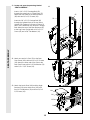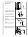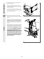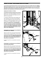
1
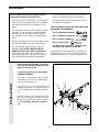
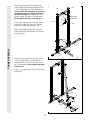
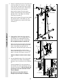
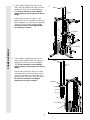
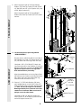
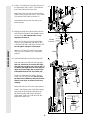
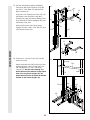
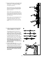
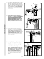
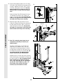
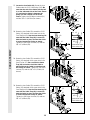
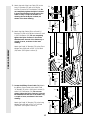
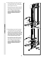
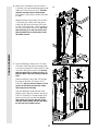
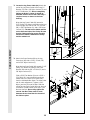
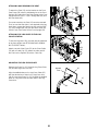
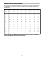
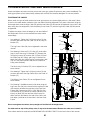
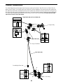
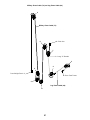
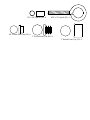
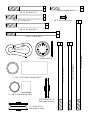
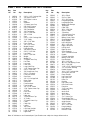
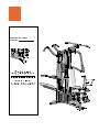
Model No. 831.159380
Serial No.
TABLE OF CONTENTS
IMPORTANT PRECAUTIONS . . . . . . . . . . . . . . . . . . . . . . . . . . . . . . . . . . . . . . . . . . . . . . . . . . . . . . . . . . . . . .2
BEFORE YOU BEGIN . . . . . . . . . . . . . . . . . . . . . . . . . . . . . . . . . . . . . . . . . . . . . . . . . . . . . . . . . . . . . . . . . . .3
ASSEMBLY . . . . . . . . . . . . . . . . . . . . . . . . . . . . . . . . . . . . . . . . . . . . . . . . . . . . . . . . . . . . . . . . . . . . . . . . . . .4
HOW TO USE THE HOME GYM SYSTEM . . . . . . . . . . . . . . . . . . . . . . . . . . . . . . . . . . . . . . . . . . . . . . . . . . .22
WEIGHT RESISTANCE CHART . . . . . . . . . . . . . . . . . . . . . . . . . . . . . . . . . . . . . . . . . . . . . . . . . . . . . . . . . . .24
TROUBLE-SHOOTING AND MAINTENANCE . . . . . . . . . . . . . . . . . . . . . . . . . . . . . . . . . . . . . . . . . . . . . . . .25
CABLE DIAGRAMS . . . . . . . . . . . . . . . . . . . . . . . . . . . . . . . . . . . . . . . . . . . . . . . . . . . . . . . . . . . . . . . . . . . .26
ORDERING REPLACEMENT PARTS . . . . . . . . . . . . . . . . . . . . . . . . . . . . . . . . . . . . . . . . . . . . . . . .Back Cover
FULL 90 DAY WARRANTY . . . . . . . . . . . . . . . . . . . . . . . . . . . . . . . . . . . . . . . . . . . . . . . . . . . . . . . .Back Cover
Note: A PART IDENTIFICATION CHART and a PART LIST/EXPLODED DRAWING are attached to the center of
this manual. Remove them before beginning assembly.
IMPORTANT PRECAUTIONS
WARNING: To reduce the risk of serious injury, read the following important precautions before using
the home gym system.
1. It is the responsibility of the owner to ensure
that all users of the home gym system are
adequately informed of all precautions.
9. Never release the press arm, butterfly arms,
military press arm, leg lever, leg press plate,
lat bar or nylon strap when weights are
raised. The weights will fall with great force.
2. The home gym system is intended for home
use only. Do not use the home gym system in
any commercial, rental, or institutional setting.
10. Keep hands and feet away from moving parts.
Always wear athletic shoes for foot protection.
11. Keep your hands away from the assist
upright when the assist arm is being used.
Your hand could become pinched between
the assist upright and the assist arm.
3. Read all instructions in this manual and in
the accompanying literature before using the
home gym system.
4. Use the home gym system only on a level
surface. Cover the floor beneath the home
gym system for protection.
12. Always be sure that your body weight is fully
supported by the dip arms or the pull-up
arms before kneeling on the assist arm. The
assist arm can drop quickly when your body
weight is placed on it.
5. Inspect and tighten all parts often. Replace
any worn parts immediately.
13. Make sure that the cables remain on the pulleys at all times. If the cables bind while you
are exercising, stop immediately and make
sure that the cables are on all of the pulleys.
6. Keep small children and pets away from the
home gym system at all times.
7. Always stand on a foot plate when performing an exercise that could cause the home
gym system to tip.
14. Always disconnect the lat bar from the home
gym system when performing an exercise
that does not use the lat bar.
8. Keep your hands away from the leg press
upright when the military press arm is being
used. Your hand could become pinched
between the leg press upright and the military press arm.
15. If you feel pain or dizziness at any time while
exercising, stop immediately and begin cooling down.
WARNING: Before beginning this or any exercise program, consult your physician. This is especially
important for persons over the age of 35 or persons with pre-existing health problems. Read all
instructions before using. SEARS assumes no responsibility for personal injury or property damage
sustained by or through the use of this product.
2
3
ASSEMBLY
Before beginning assembly, carefully read the
following information and instructions:
• As you assemble the PRO 9645 be sure that all
parts are oriented as shown in the drawings.
• Place all parts of the PRO 9645 in a cleared area
and remove the packing materials; do not dispose
of the packing materials until assembly is completed.
• Tighten all parts as you assemble them, unless
instructed to do otherwise.
THE FOLLOWING TOOLS (NOT INCLUDED) ARE
REQUIRED FOR ASSEMBLY:
• The assembly is broken into four stages: 1) frame
assembly, 2) arm assembly, 3) cable and pulley
assembly, and 4) seat and backrest assembly.
The hardware for each stage is packaged separately.
• Two (2) adjustable wrenches
• One (1) standard screwdriver
• One (1) phillips screwdriver
• Wait until you begin each assembly stage to open
the parts bag labeled for that assembly stage.
• One (1) rubber mallet
• Lubricant, such as grease or petroleum jelly,
and soapy water will also be needed.
• For help identifying the small parts used in
assembly, use the PART IDENTIFICATION
CHART located in the center of this manual.
Note: Some small parts may have been preattached for shipping. If a part is not in the parts
bag, check to see if it has been pre-attached.
Assembly will be more convenient if you have the
following tools: A socket set, a set of open-end or
closed-end wrenches, or a set of ratchet wrenches.
1. Before beginning assembly, be sure that
you have read and understand the information in the box above.
1
FRAME ASSEMBLY
Locate and open the parts bag labeled
“FRAME ASSEMBLY.”
Press two 2” Square Outer Caps (51) onto
the Stabilizer (5). Press a 2” Square Inner
Cap (27) into the Base (4).
11
Insert six 5/16” x 2 1/2” Carriage Bolts (1) up
through the Stabilizer (5). Insert two 5/16” x
2 1/2” Carriage Bolts up through the Base
(4).
51
8
5
1
Attach the Base (4) to the Stabilizer (5) with
two 5/16” x 2 3/4” Bolts (11), two 5/16” Flat
Washers (8), and two 5/16” Nylon Locknuts
(3). Do not tighten the Nylon Locknuts
yet.
51
1
3
4
1
27
4
2. Slide the Assist Upright (74) and the Leg
Press Upright (56) onto the indicated 5/16” x
2 1/2” Carriage Bolts (1) in the Stabilizer (5).
The high side of the brackets on the Assist
Upright and Leg Press Upright should be
on the side shown. Hand-tighten four 5/16”
Nylon Locknuts (3) onto the Carriage Bolts.
Do not tighten the Nylon Locknuts yet.
2
27
27
87
High Sides
of Brackets
91
74
Press two 2” Square Inner Caps (27) into the
Leg Press Upright (56). Press a 2” Square
Inner Cap into the Assist Upright (74).
56
27
Attach the Rubber Bumper (91) to the Leg
Press Upright (56) with the #8 x 1/2” Self-tapping Screw (87).
3
5
FRAME ASSEMBLY
1
1
3. Slide the Front Upright (42) onto the 5/16” x
2 1/2” Carriage Bolts (1) in the Base (4).
Hand-tighten a 5/16” Nylon Locknut (3) onto
each Carriage Bolt. Do not tighten the Nylon
Locknuts yet.
3
Press a 1” Square Inner Cap (6) into the Front
Upright (42).
42
6
3
4
1
5
4. Press a 2” Square Inner Cap (27) into the end
of the Top Frame (55). Press a 1 3/4” Square
Inner Cap (44) into each end of the crossbar
on the Top Frame. Press two 1” Round Inner
Caps (49) into the top of the crossbar.
4
11
55
49
44
8
27
3
Attach the Top Frame (55) to the Assist
Upright (74) and the Leg Press Upright (56)
with two 5/16” x 2 3/4” Bolts (11) and two
5/16” Nylon Locknuts (3).
Crossbar
44
Attach the Top Frame (55) to the Front Upright
(42) with two 5/16” x 2 3/4” Bolts (11), two
5/16” Flat Washers (8), and two 5/16” Nylon
Locknuts (3).
3
11
56
42
FRAME ASSEMBLY
74
5. Slide the Rear Seat Frame (100) onto the
indicated 5/16” x 2 1/2” Carriage Bolts (1) in
the Stabilizer (5). Hand-tighten two 5/16”
Nylon Locknuts (3) onto the Carriage Bolts.
Do not tighten the Nylon Locknuts yet.
5
1
100
Attach the other end of the Rear Seat Frame
(100) to the Leg Press Upright (56) with two
5/16” x 2 3/4” Bolts (11), two 5/16” Flat
Washers (8), and two 5/16” Nylon Locknuts (3).
11
3
56
8
Attach the Handle (82) to the Rear Seat
Frame (100) with two 5/16” x 2 1/2” Carriage
Bolts (1) and two 5/16” Nylon Locknuts (3).
3
3
82
Tighten all Nylon Locknuts used in steps
1–5.
6. Set two Weight Bumpers (19) on the bracket
on the Base (4) as shown. Set two Weight
Bumpers (19) on the bracket on the Stabilizer
(5).
Stack ten Weights (25) onto the bracket on
the Stabilizer (5). Stack eight Weights onto the
bracket on the Base (4). Be sure that the pin
grooves are all on the same side of each
stack of Weights.
1
5
6
Pin
Grooves
25
25
19
Be careful not to tip either stack of
Weights (25) until step 8 is complete.
5—Bracket
4—Bracket
6
Pin
Grooves
19
7. Press a Weight Tube Bumper (64) into the
end of the Short Weight Tube (108). Insert the
Weight Tube into the front stack of Weights
(25). Be sure that the pin on the Weight
Tube is sitting in the pin grooves in the top
Weight.
7
Holes
62
Lubricate the inside of the holes in a Top
Weight (65). Set the Top Weight onto the front
stack of Weights (25). Insert both Long Weight
Guides (62) into the stack of Weights. Be
sure that the holes in the Weight Guides
are at the top, as shown.
65
Lubricate
Pin
108
64
FRAME ASSEMBLY
Pin Grooves
25
8. Press a Weight Tube Bumper (64) into the
end of the Long Weight Tube (63). Insert the
Weight Tube into the rear stack of Weights
(25). Be sure that the pin on the Weight
Tube is sitting in the pin grooves in the top
Weight.
Lubricate the inside of the holes in the other
Top Weight (65). Set the Top Weight onto the
rear stack of Weights (25). Insert both Short
Weight Guides (73) into the stack of Weights.
Be sure that the holes in the Weight
Guides are at the top, as shown.
8
Holes
73
Lubricate
65
Pin
63
64
Pin Grooves
25
7
9. Attach the upper ends of the Short Weight
Guides (73) to the Top Frame (55) with a 5/16”
x 6” Bolt (60), two 1/2” x 3/4” Spacers (61), and
a 5/16” Nylon Locknut (3).
61
61
3
3
60
73
55
60
FRAME ASSEMBLY
Attach the upper ends of the Long Weight
Guides (62) to the Top Frame (55) in the same
manner.
9
62
10. Locate and open the parts bag labeled
“ARM ASSEMBLY.”
10
27
95
Welded
Tube
Be sure there is a Bushing (98) in each side of
the Stabilizer (5). Press a 2” Square Inner Cap
(27) into each end of the Leg Press Arm (96).
ARM ASSEMBLY
97
96
Lubricate a 3/8” x 3 1/4” Bolt (67). Attach the
Leg Press Arm (96) to the Stabilizer (5) with the
Bolt and a 3/8” Nylon Locknut (21). Do not overtighten the Nylon Locknut. The Leg Press
Arm must be able to pivot freely.
Align the welded tubes on the Leg Press Plate
(95) with one set of holes in the Leg Press Arm
(96). Attach the Leg Press Plate to the Leg
Press Arm with the Press Pin (97).
8
27
67—Lubricate
5
27
98
11
11. Press a 1” x 7/8” Plastic Bushing (90) onto
each welded spacer on the Press Frame (17).
Slide the Press Frame into place onto the Base
(4). Note: This will be a tight fit. The Plastic
Bushings should fit on each end of the indicated tube in the Base. Make sure that the
pulleys are on the side shown.
Lubricate the 3/8” x 8” Bolt (59). Attach the
Press Frame (17) to the Base (4) with the Bolt
and a 3/8” Nylon Locknut (21).
21
17
Pulleys
must be on
this side
59—Lubricate
21
Welded Spacers
4
Tube
90
12. Press a 1” Round Inner Cap (49) into one of
the Press Arms (46). Press a 1 3/4” Square
Inner Cap (44) into the Press Arm.
12
44
49
Attach the Press Arm (46) to one side of the
Press Frame (17) with two 5/16” x 2 1/2” Bolts
(22) and two 5/16” Nylon Locknuts (3).
46
22
Assemble the other Press Arm (46) in the
same manner.
46
3
17
13. Identify the Right Arm (48) and the Left Arm
(47). Note the position of the welded bracket
on each Arm. Arm identification is very
important for step 14.
50
31
50
Attach a “V”-Pulley (50) and a Long Cable
Trap (31) to the Right Arm (48) with a 3/8” x
2 1/2” Bolt (86) and a 3/8” Nylon Locknut (21).
Do not tighten the Nylon Locknut yet.
ARM ASSEMBLY
31
86
13
47
Welded
Brackets
21
Attach a “V”-Pulley (50) and a Long Cable
Trap (31) to the Left Arm (47) in the same
manner.
48
14. Lubricate both axles on the Top Frame (55).
14
55
Slide the Right Arm (48) onto the right axle.
Note: Be careful not to confuse the Right
Arm with the Left Arm (47); refer to step 13
to identify the Right Arm. Be sure that the
upper end of the Right Arm is behind the
indicated bracket on the Top Frame (55).
Tap two 1” Retainers (69) and a 1” Round
Cover Cap (70) onto the axle. Be sure that
the teeth on the Retainers bend toward the
Round Cover Cap, as shown in the inset
drawing.
Bracket
47
Lubricate
Axle
48
69
45
70
Attach the Left Arm (47) in the same manner.
44
Press 1 3/4” Square Inner Caps (44) into the
lower ends of the Right and Left Arms (47,
48). Wet the lower end of each Arm with
soapy water. Slide a 10” Pad (45) onto the
lower end of each Arm.
44
45
Axle
69
70
9
15. See the inset drawing. Attach the Military
Press Arm (84) to the Pivot Arm (101) with
two 5/16” x 2 1/4” Bolts (33) and two 5/16”
Nylon Locknuts (3).
Press two 1 1/2” Square Inner Caps (32) into
the Military Press Arm (84). Press two 1”
Round Inner Caps (49) into the Military Press
Arm. Slide two 5” Plastic Handgrips (83) onto
the Military Press Arm.
Attach the Pivot Arm (101) to the Assist
Upright (74) with a 3/8” x 3 1/4” Bolt (67) and
a 3/8” Nylon Locknut (21).
15
32
49
32
21
84
83
101
67
74
56
33
ARM ASSEMBLY
101
84
3
16. Press two 1” x 2” Inner Caps (107) into the
Assist Arm (105).
16
Bracket
105
Attach the Assist Arm (105) to the Leg Press
Upright (56) with a 3/8” x 6” Bolt (106), two
3/8” Flat Washers (9), and a 3/8” Nylon
Locknut (21). See the inset drawing. The
Assist Arm must be attached to the lowest
hole in the Leg Press Upright (56). The
Assist Arm must also be below the welded
bracket on the Assist Upright (74).
56
74
56
74
105
10
106
9
107
9
21
17. Attach the Left Pull-up Arm (75) and the Right
Pull-up Arm (77) to the Assist Upright (74)
with two 5/16” x 2 3/4” Bolts (11) and two
5/16” Nylon Locknuts (3).
Attach the Left Dip Arm (78) and the Right
Dip Arm (79) to the Assist Upright (74) with
two 5/16” x 2 3/4” Bolts (11) and two 5/16”
Nylon Locknuts (3).
Wet the ends of the Left and Right Pull-up
Arms (75, 77) with soapy water. Slide a Long
Foam Handgrip (113) onto each Pull-up Arm.
Press two 1 1/4” Round Inner Caps (109) into
each Pull-up Arm.
Wet the ends of the Left and Right Dip Arms
(78, 79) with soapy water. Slide a Short
Handgrip (80) onto each Dip Arm. Press a
1 1/4” Round Inner Cap (109) into each Dip
Arm.
18. Locate and open the parts bags labeled
“CABLE ASSEMBLY” and “PULLEYS.”
During steps 19 through 39, refer to the
CABLE DIAGRAMS on pages 26–27 of this
manual to verify proper cable routing. Before
beginning this section, fully unwind the four
Cables. Identify the four Cables by comparing
the lengths and ends of the Cables. The
approximate length of each Cable is listed (in
inches) after the key number in the drawing.
IMPORTANT: While assembling the cables,
do not overtighten the bolts and nuts
attaching the pulleys. The pulleys must be
able to turn freely.
19. Locate the High Cable (58). Wrap the High
Cable around a 3 1/2” Pulley (15). Attach the
Pulley to the Top Frame (55) with a 3/8” x
3 3/4” Bolt (88) and a 3/8” Nylon Locknut (21).
Be sure that the end of the Cable with the
ball is on the indicated side of the Pulley
and that the Cable is between the Pulley
and the hook.
11
20. Wrap the High Cable (58) around a “V”-Pulley
(50). Attach the “V”-Pulley and a Long Cable
Trap (31) to the indicated bracket on the Front
Upright (42) with a 3/8” x 2 1/2” Bolt (86) and
a 3/8” Nylon Locknut (21). Be sure that the
Long Cable Trap is positioned to hold the
Cable in place.
20
86
31
58
50
Bracket
42
21
21. Route the High Cable (58) around the “V”Pulley (50) on the Left Arm (47). Be sure that
the Cable is in the groove of the Pulley
and that the Long Cable Trap (31) is positioned to hold the Cable in place. Tighten
the 3/8” x 2 1/2” Bolt (86) and the 3/8” Nylon
Locknut (not shown).
21
86
31
50
CABLE ASSEMBLY
58
47
22. Route the High Cable (58) around the “V”Pulley (50) on the Right Arm (48). Be sure
that the Cable is in the groove of the “V”Pulley and that the Long Cable Trap (31) is
turned to hold the Cable in place. Tighten
the 3/8” x 2 1/2” Bolt (86) and the 3/8” Nylon
Locknut (not shown).
22
31
86
58
23. Attach the Pulley Bracket (20) to the Top
Frame (55) with the 5/16” x 5” Bolt (68) and a
5/16” Nylon Locknut (3). Do not overtighten
the Nylon Locknut; the Pulley Bracket
must be able to move freely.
See the inset drawing. Route the High Cable
(58) around the 3 1/2” Pulley (15) attached to
the Pulley Bracket (20). Tighten the 3/8” x 2”
Bolt (12) and a 3/8” Nylon Locknut (not
shown). Be sure that the Cable is in the
groove of the Pulley and that the Cable
Trap (66) is turned to hold the Cable in
place.
12
23
50
48
68
55
66
20
12
15
3
58
24. See the inset drawing. Attach a 3 1/2” Pulley
(15) and a Cable Trap (66) to the upper hole in
a Long “U”-Bracket (57) with a 3/8” x 2” Bolt
(12) and a 3/8” Nylon Locknut (21). Be sure
that the Cable Trap is inside the Long “U”Bracket. Note: This may come pre-assembled.
24
58
66
CABLE ASSEMBLY
15
21
Route the High Cable (58) through the Long
“U”-Bracket (57) and the 3 1/2” Pulley (15)
shown in the inset drawing. Be sure that the
Cable is in the groove of the Pulley and that
the Cable and Pulley move smoothly.
25. Wrap the High Cable (58) around a 3 1/2”
Pulley (15). Attach the Pulley to the bracket on
the Top Frame (55) with a 3/8” x 2” Bolt (12)
and a 3/8” Nylon Locknut (21). Be sure that
the Cable is in the groove of the Pulley and
that the Cable and Pulley move smoothly.
15
57
58
12
57
25
Bracket
55
12
58
15
21
26. Note: This assembly step shows how to
complete the assembly of several preattached parts.
26
The 5/8” x 9/16” Spacer (7) has been preattached on the outside of the 3 1/2” Low
Pulley (102) for shipping purposes. Remove
the 3/8” Nylon Locknut (21), the Spacer, and
the Pulley from the 3/8” x 3 3/4” Bolt (88). Do
not remove the Bolt. The Bolt has been
shown removed for part identification.
Reattach the 3 1/2” Low Pulley (102), with the
5/8” x 9/16” Spacer (7) between the Pulley and
the Press Frame (17). Do not tighten the 3/8”
Nylon Locknut (21) yet. Be sure that the
3/8” x 3 3/4” Bolt (88), the 3/8” Flat Washer
(9), the 5/8” x 9/16” Spacer (7), the 3 1/2”
Low Pulley (102), and the 3/8” Nylon
Locknut (21) are oriented as shown.
9
88
7
17
102
21
13
27. Locate the Low Cable (23). Route the Low
Cable under the 3 1/2” Low Pulley (102). Be
sure that the end of the Cable with the ball
is on the indicated side of the Press Frame
(17) and that the Cable is between the
Pulley and the crossbar on the Press
Frame. Tighten the 3/8” Nylon Locknut (21)
and the 3/8” x 3 3/4” Bolt (not shown).
27
21
102
23
Ball
17
Crossbar
28. Route the Low Cable (23) around the 3 1/2”
Pulley (15) attached to the lower hole in the
Front Upright (42). See the inset drawing. Be
sure that the Cable Trap (66) is turned to
hold the Cable in place and that the Cable
is routed around the Pulley as shown.
Tighten the 3/8” Nylon Locknut (21) and the
3/8” x 3 3/4” Bolt (88).
23
28
42
88
66
42
15
Inset shows view
from other side
21
CABLE ASSEMBLY
15
23
29. Route the Low Cable (23) around the 3 1/2”
Pulley (15) attached to the upper hole in the
Press Frame (17). Be sure that the Cable
Trap (66) is turned to hold the Cable in
place and that the Cable is routed around
the Pulley as shown. Tighten the 3/8” Nylon
Locknut (21) and the 3/8” x 3 1/2” Bolt (not
shown).
30. Route the Low Cable (23) around the 3 1/2”
Pulley (15) attached to the upper hole in the
Front Upright (42). See the inset drawing. Be
sure that the Cable Trap (66) is turned to
hold the Cable in place and that the Cable
is routed around the Pulley as shown.
Tighten the 3/8” Nylon Locknut (21) and the
3/8” x 3 3/4” Bolt (88).
14
29
23
15
21
66
17
30
23
15
23
88
42
15
42
21
66
Inset shows view
from other side
31. Attach the end of the Low Cable (23) to the
Long “U”-Bracket (57) with a 1/4” Nylon
Locknut (2) and a 1/4” Flat Washer (10). Do
not completely tighten the Nylon Locknut.
It should be threaded onto the end of the
Cable so only a couple of threads are
showing above the Nylon Locknut, as
shown in the inset drawing.
31
57
2
2
10
23
10
57
23
CABLE ASSEMBLY
32. Attach the High Cable (58) to a Small “U”Bracket (71) with a 1/4” Nylon Locknut (2) and
a 1/4” Flat Washer (10). Do not completely
tighten the Nylon Locknut. It should be
threaded onto the end of the Cable only a
couple of turns, as shown in the inset
drawing.
32
58
Attach the Small “U”-Bracket (71) to the Short
Weight Tube (108) with a 5/16” x 1 3/4” Bolt
(24) and a 5/16” Nylon Locknut (3).
3
71
108
24
10
2
58
71
10
2
33. Locate the Military Press Cable (72). Attach
the Military Press Cable to the other Small
“U”-Bracket (71) with a 1/4” Nylon Locknut (2)
and a 1/4” Flat Washer (10). Do not completely tighten the Nylon Locknut. It should
be threaded onto the end of the Cable only
a couple of turns, as shown in the inset
drawing.
Attach the Small “U”-Bracket (71) to the Long
Weight Tube (63) with a 5/16” x 1 3/4” Bolt
(24) and a 5/16” Nylon Locknut (3).
33
72
3
71
24
63
71
72
2
10
2
15
10
34. Wrap the Military Press Cable (72) around a
“V”-Pulley (50). Attach the “V”-Pulley to the
Top Frame (55) with a 3/8” x 2 1/2” Bolt (86)
and a 3/8” Nylon Locknut (21).
34
55
50
Wrap the Military Press Cable (72) around a 3
1/2” Pulley (15). Attach the Pulley to the indicated bracket on the Assist Arm (105) with a
3/8” x 1 3/4” Bolt (76) and a 3/8” Nylon
Locknut (21). Be sure that the Cable is
between the Pulley and the Assist Arm
and that the Cable and Pulley move
smoothly.
21
86
72
21
76
CABLE ASSEMBLY
15
Bracket
105
35. Wrap the Military Press Cable (72) around a
“V”-Pulley (50). Attach the “V”-Pulley and a
Long Cable Trap (31) to the Assist Upright
(74) with a 3/8” x 4 1/2” Bolt (112), a 3/8” Flat
Washer (9), and a 3/8” Nylon Locknut (21). Be
sure that the Long Cable Trap is turned to
hold the Cable in place and that the Cable
is routed around the Pulley as shown.
Wrap the Military Press Cable (72) around a
3 1/2” Pulley (15). Attach the Pulley to the
other bracket on the Assist Arm (105) with a
3/8” x 1 3/4” Bolt (76) and a 3/8” Nylon
Locknut (21). Be sure that the Cable is
between the Pulley and the Assist Arm
and that the Cable and Pulley move
smoothly.
35
74
21
31
50
21
9
72
11
105
76
Bracket
15
16
36. Slide a 5/16” Flat Washer (8) onto a 5/16” x
2 3/4” Bolt (11). Insert the Bolt through the indicated hole in the Pivot Arm (101). The Bolt
must be inserted from the side shown.
Fully tighten a 5/16” Nylon Jam Nut (93) onto
the Bolt.
36
21
93
Wrap the Military Press Cable (72) around a
3 1/2” Pulley (15). Attach the Pulley and a
Cable Trap (66) to the Pivot Arm (101) with
the 3/8” x 3 3/4” Bolt (88), a 3/8” Flat Washer
(9), and a 3/8” Nylon Locknut (21). Be sure
that the Pulley is on the side shown and
that the Cable Trap is positioned to hold
the Cable in place.
9
8
101
11
72
15
CABLE ASSEMBLY
66
37. See inset drawing A. Attach a 3 1/2” Pulley
(15) and a Cable Trap (66) to the upper hole
in a Long “U”-Bracket (57) with a 3/8” x 2” Bolt
(12) and a 3/8” Nylon Locknut (21). Be sure
that the Cable Trap is inside the Long “U”Bracket. (Note: This may come pre-assembled.)
37
21
57
93
72
1
15 57
72
17
A
15
Route the Military Press Cable (72) through
the Long “U”-Bracket (57) and the 3 1/2”
Pulley (15). Be sure that the Cable is in the
groove of the Pulley and that the Cable
and Pulley move smoothly.
See inset drawing B. Slide the end of the
Military Press Cable (72) onto the end of the
5/16” x 2 3/4 Bolt (11). Thread another 5/16”
Nylon Jam Nut (93) onto the Bolt. Do not
fully tighten the second Jam Nut. There
must be room between the two Jam Nuts
for the end of the Cable to pivot.
88
66
12
B
38. Locate the Leg Press Cable (99). Attach the
end of the Leg Press Cable to the Long “U”Bracket (57) with a 1/4” Nylon Locknut (2) and
a 1/4” Flat Washer (10). Do not completely
tighten the Nylon Locknut. It should be
threaded onto the end of the Cable only a
couple of turns, as shown in the inset
drawing.
38
2
57
10
Wrap the Leg Press Cable (99) around a
3 1/2” Pulley (15). Attach the Pulley to the Leg
Press Upright (56) with the 3/8” x 3 3/4” Bolt
(88), a 3/8” Flat Washer (9), and a 3/8” Nylon
Locknut (21). The ball on the Cable must be
on the indicated side of the Pulley. Be sure
that the Cable and Pulley move smoothly
and that the Cable is between the Pulley
and the welded rod.
99
56
Ball
88
15
9
21
CABLE ASSEMBLY
2
Welded
Rod
10
57
99
39. Attach the Press Bracket (94) to the Leg
Press Arm (96) with a 5/16” x 3” Bolt (111)
and a 5/16” Nylon Locknut (3).
39
Wrap the Leg Press Cable (99) around a 3 1/2”
Pulley (15). Attach the Pulley to the Press
Bracket (94) with the 3/8” x 2” Bolt (12) and a
3/8” Nylon Locknut (21).
Slide a 5/16” Flat Washer (8) onto a 5/16” x
2 3/4” Bolt (11). Insert the Bolt through the
lowest hole in the Rear Seat Frame (100)
from the indicated side. (Note: The three holes
are for cable adjustment.) Tighten a 5/16”
Nylon Jam Nut (93) onto the Bolt. Slide the
end of the Leg Press Cable (99) onto the end
of the Bolt. Thread another 5/16” Nylon Jam
Nut onto the Bolt. Do not fully tighten the
second Jam Nut. There must be room
between the two Jam Nuts for the end of
the Cable to pivot.
96
3
11
8
99
12
94
111
15
21
100
93
18
40. Locate and open the parts bag labeled
“SEAT ASSEMBLY.”
40
Insert a 1/4” x 2 1/2” Carriage Bolt (92)
through the center hole in a Seat Plate (37).
Attach the Seat Plate to the Rear Backrest
(85) with two 1/4” x 1/2” Screws (18).
85
56
Insert the 1/4” x 2 1/2” Carriage Bolt (92)
through the indicated hole in the Leg Press
Upright (56). Tighten a 1/4” Nylon Locknut (2)
with a 1/4” Flat Washer (10) onto the Carriage
Bolt. Attach the top of the Rear Backrest (85)
to the Leg Press Upright with a 1/4” x 2 1/2”
Screw (43) and a 1/4” Flat Washer (10).
18
37 92
43
10
SEAT ASSEMBLY
2
41. Attach one end of a Seat (13) to the Rear
Seat Frame (100) with two 1/4” x 1/2” Screws
(18). Attach the other end of the Seat to the
Rear Seat Frame with a 1/4” Flat Washer (10)
and a 1/4” x 2 1/2” Screw (43).
41
13
100
18
10
43
42. Attach the Assist Seat (104) and the Angle
Bracket (110) to the Assist Arm (105) with
four 1/4” Flat Washers (10) and four 1/4” x 2
1/2” Screws (43).
42
104
110
105
10
10
43
19
18
43. Attach the Front Backrest (41) to the Front
Upright (42) with two 1/4” x 2 1/2” Screws (43)
and two 1/4” Flat Washers (10). The Backrest
must be oriented as shown.
43
42
41
43 10
Thick
End
44. Press a 1 1/2” Square Inner Cap (32) into the
Front Seat Frame (36).
Insert a 1/4” x 2” Carriage Bolt (38) through
the center hole in the Seat Plate (37). Attach
the Seat Plate to the Seat (13) with two 1/4” x
1/2” Screws (18).
44
13
38
SEAT ASSEMBLY
Insert the 1/4” x 2” Carriage Bolt (38) through
the indicated hole in the Front Seat Frame
(36). Tighten a 1/4” Nylon Locknut (2) with a
1/4” Flat Washer (10) onto the Carriage Bolt.
37
Attach the other end of the Seat (13) to the
Front Seat Frame (36) with a 1/4” Flat Washer
(10) and a 1/4” x 2” Machine Screw (81).
45. Press a 1 1/2” Square Inner Cap (32) into the
Leg Lever (29).
32
18
36
10
81
2
45
Lubricate the 5/16” x 2 1/4” Bolt (33). Attach
the Leg Lever (29) to the Front Seat Frame
(36) with the Bolt and a 5/16” Nylon Locknut
(3).
36
3
Lubricate—33
Insert the 5/16” x 2” Eyebolt (35) into the Leg
Lever (29) from the direction shown. Tighten a
5/16” Nylon Locknut (3) with a 5/16” Flat
Washer (8) onto the Eyebolt.
29
8
35
3
32
46. Rest the Front Seat Frame (36) on the indicated pin in the Front Upright (42). Attach the
Front Seat Frame to the Front Upright with a
5/16” x 2 3/4” Carriage Bolt (14) and the Seat
Knob (40).
46
42
40
14
Pin
20
36
SEAT ASSEMBLY
47. Press two 3/4” Round Inner Caps (34) into
each Pad Tube (28).
47
30
34
28
Insert the other Pad Tube (28) into the Leg
Lever (29). Slide a Foam Foam Pad (30) onto
each end of the Pad Tube.
34
30
29
48. Remove the backing from the PRO 9645
decal and apply it to the home gym system as
shown.
Make sure that all parts have been properly
tightened. The use of the remaining parts will
be explained in HOW TO USE THE HOME
GYM SYSTEM, beginning on page 22 of this
manual.
DECAL
36
Insert a Pad Tube (28) into the Front Seat
Frame (36). Slide a Foam Pad (30) onto each
end of the Pad Tube.
48
PRO 9645
Before using the home gym system, pull each
cable a few times to be sure that the cables
move smoothly over the pulleys. If one of the
cables does not move smoothly, find and correct the problem. IMPORTANT: If the cables
are not properly installed, they may be
damaged when heavy weight is used. See
the CABLE DIAGRAMS on pages 26 and 27
of this manual for proper cable routing. If
there is any slack in the cables, you will
need to remove it by tightening the cables.
See TROUBLE-SHOOTING AND MAINTENANCE on page 25.
21
HOW TO USE THE HOME GYM SYSTEM
The instructions below describe how each part of the home gym system can be adjusted. Refer to the exercise
poster accompanying this manual to see how the home gym system should be set up for each exercise. IMPORTANT: When attaching the lat bar or nylon strap, make sure that the attachments are in the correct starting position for the exercise to be performed. If there is any slack in the cables or chain as an exercise is
performed, the effectiveness of the exercise will be reduced.
CHANGING THE WEIGHT SETTING
The PRO 9645 features two weight stacks. The front
weight stack is connected to the upper and lower pulleys, the press arm, and the butterfly arms. The rear
weight stack is connected to the military press arm,
assist arm, and leg press.
26
To change the weight setting of either weight stack,
insert a Weight Pin (26) under the desired Weight
(25). Insert the Weight Pin until the bent end of the
Weight Pin is touching the Weights, and turn the bent
end downward. The weight setting of either weight
stack can be changed from 6.5 pounds to 106.5
pounds, in increments of 12.5 pounds. Note: Due to
the cables and pulleys, the amount of resistance
at each exercise station may vary from the weight
setting. Use the WEIGHT RESISTANCE CHART on
page 24 to find the approximate amount of resistance at each weight station.
25
25
26
ATTACHING THE LAT BAR OR NYLON STRAP TO
THE HIGH PULLEY STATION
53
Attach the Lat Bar (54) to the High Cable (58) with a
Cable Clip (53). For some exercises, the Chain (52)
should be attached between the Lat Bar and the High
Cable with two Cable Clips. Adjust the length of the
Chain between the Lat Bar and the High Cable so
the Lat Bar is in the correct starting position for
the exercise to be performed.
52
58
53
54
The Nylon Strap (39) can be attached in the same
manner.
39
ATTACHING THE LAT BAR OR NYLON STRAP TO
THE LOW PULLEY STATION
23
53
Attach the Lat Bar (54) to the Low Cable (23) with a
Cable Clip (53). For some exercises, the Chain (52)
should be attached between the Lat Bar and the Low
Cable with two Cable Clips. Adjust the length of the
Chain between the Lat Bar and the Low Cable so
the Lat Bar is in the correct starting position for
the exercise to be performed.
52
53
39
The Nylon Strap (39) can be attached in the same
manner.
54
22
ATTACHING AND REMOVING THE SEAT
40
36
To attach the Seat (13), set the bracket on the Front
Seat Frame (36) onto the indicated pins on the Front
Upright (42). Attach the Front Seat Frame to the Front
Upright with the 5/16” x 2 3/4” Carriage Bolt (14) and
the Seat Knob (40).
13
42
For some exercises, the Seat (13) must be removed.
First, be sure that the chain is not attached to the leg
lever. Next, remove the Seat Knob (40) and the 5/16”
x 2 3/4” Carriage Bolt (14) from the Seat Frame (36).
Lift the Front Seat Frame off the Front Upright (42).
14
ATTACHING THE LEG LEVER TO THE LOW
PULLEY STATION
To use the Leg Lever (29), the seat must be attached
to the front upright (see ATTACHING AND REMOVING THE SEAT above).
53
Attach one end of the Chain (52) to the Short Cable
(23) with a Cable Clip (53). Attach the other end of
the Chain to the Eyebolt (35) with a Cable Clip.
29
35
52
53
23
ADJUSTING THE LEG PRESS PLATE
Remove the Press Pin (97) from the Leg Press Plate
(95) and the Leg Press Arm (96).
95
Welded
Tube
Align the welded tubes on the Leg Press Plate (95)
with the desired set of holes in the Leg Press Arm
(96). Re-insert the Press Pin (97) through the welded
tubes on Leg Press Plate and the holes in the Leg
Press Arm.
97
96
23
WEIGHT RESISTANCE CHART
This chart shows the approximate weight resistance at each weight station. “Top” refers to the 6.5 lb. top weight.
The other numbers refer to the 12.5 lb. weight plates. The butterfly arm resistance listed is the resistance for
each butterfly arm.
WEIGHT
PRESS
ARM
BUTTERFLY
ARM
LEG
LEVER
HIGH
PULLEY
LOW
PULLEY
MILITARY
PRESS ARM
LEG
PRESS
ASSIST
ARM
PLATES
(lbs.)
(lbs.)
(lbs.)
(lbs.)
(lbs.)
(lbs.)
(lbs.)
(lbs.)
Top
31
17
25
23
36
30
36
11
1
59
35
50
36
67
51
78
38
2
81
40
71
54
95
74
123
66
3
104
70
97
70
123
97
171
95
4
132
80
111
88
155
115
219
117
5
154
110
131
98
191
135
265
142
6
196
115
156
120
220
164
299
186
7
206
130
172
135
252
183
333
213
8
227
140
184
144
273
194
387
232
9
–
–
–
–
–
218
440
256
10
–
–
–
–
–
246
455
293
The actual resistance at each weight station may vary due to differences in individual weight plates, as
well as friction between the cables, pulleys, and weight guides.
24
TROUBLE-SHOOTING AND MAINTENANCE
Inspect and tighten all parts each time you use the home gym system. Replace any worn parts immediately. The
home gym system can be cleaned using a damp cloth and mild non-abrasive detergent. Do not use solvents.
TIGHTENING THE CABLES
Woven cable, the type of cable used on the home gym system, can stretch slightly when it is first used. If there
is slack in the cables before resistance is felt, the cables should be tightened. If any slack is felt when using the
front weight stack, both the High Cable (58) and the Low Cable (23) will need to be tightened. If any slack is felt
when using the rear weight stack, both the Military Press Cable (72) and the Leg Press Cable (99) will need to
be tightened.
To tighten the cables, insert the weight pin into the middle of
the weight stack. Slack can be removed from these cables
several ways:
•
1
15
66
See drawing 1. Tighten the 1/4” Nylon Locknut (2) that
connects the end of the Low Cable (23) to the Long “U”Bracket (57).
21
12
57
The Leg Press Cable (99) can be tightened in the same
manner.
2
•
See drawing 1. Move the 3 1/2” Pulley (15) to the other
hole in one of the Long “U”-Brackets (57). Remove the
3/8” Nylon Locknut (21) and the 3/8” x 2” Bolt (12) from
the Cable Trap (66), Pulley, and Long “U”-Bracket. Reattach the Pulley and Cable Trap. Be sure that the Cable
Trap is in the proper position and that the Cable and
Pulley move smoothly.
23 or 99
2
72
58
71
2
71
The other Long “U”-Bracket (57) can be adjusted in the
same manner.
•
See drawing 2. Tighten the 1/4” Nylon Locknut (2) that
connects the end of the High Cable (58) to the Small “U”Bracket (71).
2
3
The Military Press Cable (72) can be tightened in the
same manner.
•
See Drawing 3. If additional slack is felt while using the
Leg Press Arm (96), then the end of the Leg Press Cable
(99) must be moved to the next hole in the Rear Seat
Frame (100). Remove the 5/16” x 2 3/4” Bolt (11), the
5/16” Washer (8), the end of the Cable, and both 5/16”
Nylon Jam Nuts (93) from the Rear Seat Frame. Reattach the Bolt, the Washer, the end of the Cable, and
both Nylon Jam Nuts to the next hole in the Rear Seat
Frame.
11
96
8
100
99
93
93
Do not overtighten the cables; the top weight will be lifted off the weight stack.
If a cable tends to slip off the pulleys often, it may have become twisted. Remove the cable and re-install it.
If the cables need to be replaced, see ORDERING REPLACEMENT PARTS on the back cover of this manual.
25
CABLE DIAGRAMS
The cable diagrams on these pages show the proper routing of the High Cable (58), the Low Cable (23), the
Military Press Cable (72), and the Leg Press Cable (99). Use the diagrams to be sure that the four cables and
the cable traps have been assembled correctly. If the cables have not been correctly routed, the home gym system will not function properly and damage may occur. The insets show the proper positioning of the cable traps.
The cable traps should be positioned so that the cables will not come off the pulleys. Be sure that the cable
traps do not touch or bind the cables.
High Cable (58) and Low Cable (23)
3
2
1—High Pulley
7
5
4
6
High Cable (58)
5—Long “U”-Bracket
Low Cable (23)
Front Weight Stack—8
4
3
2
26
1—Low Pulley
Military Press Cable (72) and Leg Press Cable (99)
2
Military Press Cable (72)
8—Pivot Arm
6
7
1—Long “U”-Bracket
3
2
4
Rear Weight Stack—1
4—Rear Seat Frame
3
Leg Press Cable (99)
5
27
1/2" x 3/4" Spacer (61)–4
5/16" x 2" Eyebolt (35)—1
3/4" Round Inner Cap (34)–4
1" Round Inner Cap (49)–6
1" Round Cover Cap (70)–2
1/4" x 2" Machine Screw (81)–1
5/16" Nylon Locknut(3)–36
5/16" Nylon Jam Nut(93)–4
3/8" Nylon Locknut (21)–23
1/4" Flat Washer (10)–15
5/16" Flat Washer (8)–9
1/4" x 2 1/2" Screw (43)–8
3/8" Flat Washer (9)–9
5/16" x 2 1/2" Carriage Bolt (1)–10
5/16" x 2 3/4" Carriage Bolt (14)–1
5/16" x 3" Bolt ( 111)–1
3/8" x 3 1/4" Bolt (67)–2
3/8" x 3 1/2" Bolt (16)–1
1/4" x 1/2" Screw (18)–6
3/8" x 3 3/4" Bolt (88)–6
5/16" x 5" Bolt (68)–1
Cable Clip (53)–3
1" Retainer (69)–4
1 1/8" x 2 1/2" Plastic Bushing (89)–2
1" x 7/8" Plastic Bushing (90)–2
3 1/2" Pulley (15)–13
(Not shown to scale)
"V"-Pulley (50)–5
(Not shown to scale)
??
@@@@@@@@e??
N@h?
?@h??
@?f?
@?f?
@?f?
@?f?
@?f?
@?f??
?W2@@@@6X??
W.M?e?I/X?
.YgV/??
W.?W2@6Xe?
7H?7<?B1e?
@??@e?@e?
3=?@eC5e?
V4@@@@0Ye??
W2@@@@6Xe?
7<fB1e?
@?f?@e?
3=fC5e?
V4@@@@0Ye??
?
@@@@@@@@e?
N@h?
?@h??
/XgW.?
V/K?e?O.Y?
?V4@@@@0Y???
??
?
?W&KeO@e?
?*@@@@@@e?
?V+Mg??
@@@@@@@@e???
W2@@6Xe?
7<eB1e?
@?e?@e?
3=eC5e?
S@@@@He?
W2@>@@@Le?
7<B@<?B1e?
@??@e?@e?
@??@e?@e?
@??@e?@e?
@@@@@@@@e??
??
??
??
@@@?g???
@@@?g??
W.?W2@6Xe?
7H?7<?B1e?
@??@e?@e?
3=?@eC5e?
V4@@@@0Ye??
??
?
@6KO2@e?
?B@@<?e?
?C@@=?e?
@0MI4@e??
??
?
@@@?g???
@@@?g??
W26T2@6Xe?
7<B@<?B1e?
@??@e?@e?
@?C@=?C5e?
@@@>@@0Ye?
I4@Xf?
I4@@e??
W26T2@6Xe??
7<B@<?B1e?
@??@e?@e?
@?f?@e?
??
W2@6X??@e?
7<?B1??@e?
@?e3L?@e?
3=eV/X@e?
V4@??V4@e?
@?f?
@?f?
@?f?
@?f?
@?f?
@?f??
?W2@@@@6X??
W.M?e?I/X?
.YgV/??
W2@@@@6Xe?
7<fB1e?
@?f?@e?
3=fC5e?
V4@@@@0Ye??
W.?W2@6Xe?
7H?7<?B1e?
@??@e?@e?
3=?@eC5e?
S@@@@@0Ye?
*UgW.?
V/K?e?O.Y?
?V4@@@@0Y???
??
?
?W&KeO@e?
?*@@@@@@e?
?V+Mg??
@@@@@@@@e???
W2@@6Xe?
7<eB1e?
@?e?@e?
3=eC5e?
S@@@@He?
W2@>@@@Le?
7<B@<?B1e?
@??@e?@e?
@??@e?@e?
@??@e?@e?
@@@@@@@@e??
??
?
@@@?g???
@@@?g??
W.?W2@6Xe?
7H?7<?B1e?
@??@e?@e?
3=?@eC5e?
V4@@@@0Ye??
??
@6KO2@e??
?B@@<?e?
?C@@=?e?
@0MI4@e??
??
?
@@@?g???
@@@?g??
W.?W2@6Xe?
7H?7<?B1e?
@??@e?@e?
3=?@eC5e?
V4@@@@0Ye??
@@@@@@@@e??
N@h?
J@L?g?
@@)Kg?
I46Kf?
I4@@e??
@?W2@@6Xe??
@?7<eB1e?
@?@?e?@e?
@?@?e?@e?
??
?
@@@@@@@@e?
N@h?
?@h??
?
@?f?
@?f?
@?f?
@?f?
@?f?
@?f?
?W2@@@@6X??
W.M?e?I/X?
.YgV/??
W2@@@@6Xe?
7<e@?B1e?
@?e@??@e?
3=?C5?J5e?
V4@0Y?.Ye??
@?W2@@6Xe?
@?7<eB1e?
@?@?e?@e?
3X@LeJ5e?
S@@@e.Ye?
*UgW.?
V/K?e?O.Y?
?V4@@@@0Y???
??
?
?W&KeO@e?
?*@@@@@@e?
?V+Mg??
@@@@@@@@e???
W2@@6Xe?
7<eB1e?
@?e?@e?
3=eC5e?
S@@@@He?
W2@>@@@Le?
7<B@<?B1e?
@??@e?@e?
@??@e?@e?
@??@e?@e?
@@@@@@@@e??
??
?
@@@?g???
@@@?g??
W26T2@6Xe?
7<B@<?B1e?
@??@e?@e?
3=C@=?C5e?
V40R4@0Ye??
??
?
@6KO2@e?
?B@@<?e?
?C@@=?e?
@0MI4@e??
??
?
@@@?g???
@@@?g??
W26T2@6Xe?
7<B@<?B1e?
@??@e?@e?
@?C@=?C5e?
@@@>@@0Ye?
I4@Xf?
I4@@e??
?
W26T2@6Xe?
7<B@<?B1e?
@??@e?@e?
@?f?@e?
PART LIST—Model No. 831.159380
Key
No.
Part
No.
Qty.
1
2
3
4
5
6
7
8
9
10
11
12
13
14
15
16
17
18
19
20
21
22
23
24
25
26
27
28
29
30
31
32
33
34
35
36
37
38
39
40
41
42
43
44
45
46
47
48
49
50
51
52
53
54
55
56
57
58
100291
012139
012056
133351
133352
120696
121845
014073
014132
014063
119377
013601
133379
123385
134031
120003
133360
123148
115644
133359
012149
127948
133395
102073
120294
122693
108874
133373
133358
103805
133361
103833
121421
119170
129051
133380
133362
128281
115177
119192
133357
133356
128283
113666
120596
133355
133364
133366
120733
115164
120822
116868
103087
133367
133368
133370
133375
133396
10
6
36
1
1
1
1
9
9
15
14
5
2
1
13
1
1
6
4
1
23
4
1
2
18
2
8
2
1
4
4
4
3
4
1
1
2
1
1
1
1
1
8
6
2
2
1
1
6
5
2
1
3
1
1
1
2
1
Description
5/16” x 2 1/2” Carriage Bolt
1/4” Nylon Locknut
5/16” Nylon Locknut
Base
Stabilizer
1” Square Inner Cap
5/8” x 9/16” Spacer
5/16” Flat Washer
3/8” Flat Washer
1/4” Flat Washer
5/16” x 2 3/4” Bolt
3/8” x 2” Bolt
Seat
5/16” x 2 3/4” Carriage Bolt
3 1/2” Pulley
3/8” x 3 1/2” Bolt
Press Frame
1/4” x 1/2” Screw
Weight Bumper
Pulley Bracket
3/8” Nylon Locknut
5/16” x 2 1/2” Bolt
Low Cable
5/16” x 1 3/4” Bolt
Weight
Weight Pin
2” Square Inner Cap
Pad Tube
Leg Lever
Foam Pad
Long Cable Trap
1 1/2” Square Inner Cap
5/16” x 2 1/4” Bolt
3/4” Round Inner Cap
5/16” x 2” Eyebolt
Front Seat Frame
Seat Plate
1/4” x 2” Carriage Bolt
Nylon Strap
Seat Knob
Front Backrest
Front Upright
1/4” x 2 1/2” Screw
1 3/4” Square Inner Cap
10” Pad
Press Arm
Left Arm
Right Arm
1” Round Inner Cap
“V”-Pulley
2” Square Outer Cap
Chain
Cable Clip
Lat Bar
Top Frame
Leg Press Upright
Long “U”-Bracket
High Cable
R1096A
Key
No.
Part
No.
Qty.
59
60
61
62
63
64
65
66
67
68
69
70
71
72
73
74
75
76
77
78
79
80
81
82
83
84
85
86
87
88
89
90
91
92
93
94
95
96
97
98
99
100
101
102
103
104
105
106
107
108
109
110
111
112
113
#
#
128292
128293
131516
130361
133376
122691
126866
133381
120354
128297
108778
120808
133371
133397
131911
133377
133383
013399
133382
133384
133385
133369
128276
133378
119702
133386
133372
013581
102308
118471
126891
126808
122950
121422
100427
133387
133388
133389
131522
131910
133398
133354
133353
124590
133390
133391
133392
118522
127231
133394
124819
133231
126145
013485
134434
133393
125056
1
2
4
2
1
2
2
7
2
1
4
2
2
1
2
1
1
2
1
1
1
2
1
1
8
1
1
4
1
6
2
2
1
1
4
1
1
1
1
2
1
1
1
1
2
1
1
1
2
1
6
1
1
1
2
1
1
Description
3/8” x 8” Bolt
5/16” x 6” Bolt
1/2” x 3/4” Spacer
Long Weight Guide
Long Weight Tube
Weight Tube Bumper
Top Weight
Cable Trap
3/8” x 3 1/4” Bolt
5/16” x 5” Bolt
1” Retainer
1” Round Cover Cap
Small “U”-Bracket
Military Press Cable
Short Weight Guide
Assist Upright
Left Pull-up Arm
3/8” x 1 3/4” Bolt
Right Pull-up Arm
Left Dip Arm
Right Dip Arm
Short Handgrip
1/4” x 2” Machine Screw
Handle
5” Plastic Handgrip
Military Press Arm
Rear Backrest
3/8” x 2 1/2” Bolt
#8 x 1/2” Self-tapping Screw
3/8” x 3 3/4” Bolt
1 1/8” x 2 1/2” Plastic Bushing
1” x 7/8” Plastic Bushing
Rubber Bumper
1/4” x 2 1/2” Carriage Bolt
5/16” Nylon Jam Nut
Press Bracket
Leg Press Plate
Leg Press Arm
Press Pin
Bushing
Leg Press Cable
Rear Seat Frame
Pivot Arm
3 1/2” Low Pulley
Handle Cap
Assist Seat
Assist Arm
3/8” x 6” Bolt
1” x 2” Inner Cap
Short Weight Tube
1 1/4” Round Inner Cap
Angle Bracket
5/16” x 3” Bolt
3/8” x 4 1/2” Bolt
Long Handgrip
User’s Manual
Exercise Poster
Note: “#” indicates a non-illustrated part. Specifications are subject to change without notice.
109
109
103
113
80
78
109
75
10
2
103
9
77
99
57
112
11
11
21
15
83
54
3
27
12
66
10
2
3
3 65
3
11
74
51
52
5
11
26
79
8
51
3
50
31
113
21
109
11
60
1
53
19
61
27
11 8
25
15
88
24
64
63
71
72
73
3
39
3
1
10
10
83
3
8
2
43
91
87
3
21
8
21
9
110
10
43
101
1566
98
83
83
15
11
43
10
15
3
76
9
2
9
21
107
83
57
23
15
67
27
50
21
95
27
32
21
21
10
27
111
12
106
21
105
76 15
84
49
32
21
94
96
15 66
12 3
20
33
3 8
88
100
21
99
93
13
18
85
93 72
93
3
83
10
43
3
18
67
21
104
1
82
92
37
1
11
11
11
18
9
56
27
68
12
66
97
55
25
2
3
10
60
27
3
21
86
61
4
19
108
65
24
71
64
49
44
58
62
3
8
11
1
26
88
43
3
15
10
3
9
21
49 44
12
42
21
88
50
3
27
15
86
31
15
49
6
66
14
41
44
83
34
33
18
37
21
17
21
22
34 30
35
2
13
70
30
10
38
45
44
48
69
89
46
21
81
66
36
40
58
50
31
86
3
32
8
29
32
90
21
66
3
30
34
45
44
7
102
88
49
23
44
47
16
59
15
9
46
34
30
83
28
28
3
70
69
89
EXPLODED DRAWING—Model No. 831.159380
R1096A
The model number and serial number of your WEIDER® PRO 9645
are listed on a decal attached to the frame. See the front cover of
this manual to find the location of the decal.
Model No. 831.159380
If you find that:
All replacement parts are available for immediate purchase or
special order when you visit your nearest SEARS Service Center.
To request service or to order parts by telephone, call the toll-free
numbers listed at the left.
• you need help assembling or
operating the WEIDER® PRO 9645
When requesting help or service, or ordering parts, please be prepared to provide the following information:
QUESTIONS?
• a part is missing
• or you need to schedule repair
service
call our toll-free HELPLINE
1-800-736-6879
Monday–Saturday, 7 am–7 pm
Central Time (excluding holidays)
• The MODEL NUMBER of the product (831.159380).
• The NAME of the product (WEIDER® PRO 9645 Home Gym
System).
• The PART NUMBER of the PART (see the PART LIST and the
EXPLODED DRAWING at the center of this manual).
• The DESCRIPTION of the PART (see the PART LIST and the
EXPLODED DRAWING at the center of this manual).
REPLACEMENT PARTS
If parts become worn and need to
be replaced, call the following tollfree number
1-800-FON-PART
(1-800-366-7278)
FULL 90 DAY WARRANTY
For 90 days from the date of purchase, if failure occurs due to defect in material or workmanship in this
SEARS WEIGHT SYSTEM EXERCISER, contact the nearest SEARS Service Center throughout the
United States and SEARS will repair or replace the WEIGHT SYSTEM EXERCISER, free of charge.
This warranty does not apply when the WEIGHT SYSTEM EXERCISER is used commercially or for
rental purposes.
This warranty gives you specific legal rights, and you may also have other rights which vary from state
to state.
SEARS, ROEBUCK AND CO., DEPT. 817WA, HOFFMAN ESTATES, IL 60179
Part No. 133393 R1096A
Printed in Canada © 1996 Sears, Roebuck and Co.