1
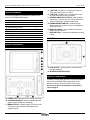
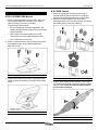
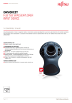
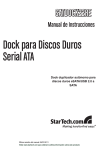
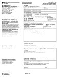
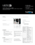
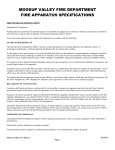
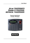
SV-CLCD56BA/70BA Quick Installation Guide June 2010 Safety Vision SV-625B-KIT, which includes the camera (Part Number SV-625B) and a 65-foot extension cable (Part Number SV-523B) and has the following features: Safety Vision SV-CLCD56BA Safety Vision SV-CLCD70BA Color TFT LCD Collision Avoidance System Quick Installation Guide y Rugged, water-resistant housing y CCD image sensor for improved image quality y Wide field of view y LEDs that generate infrared light for improved image quality in low-light situations y Integrated microphone Important Safety Precautions Install and operate the SV-CLCD56BA/70BA system with the following safety precautions in mind: The ground (black) wire of the control box system power cable must be connected directly to the vehicle chassis. Use only the correct voltage (12 to 24 VDC). To reduce the risk of electrical shock, disconnect the battery from the electrical system of the vehicle before starting the installation. Overview The Safety Vision SV-CLCD56BA and SV-CLCD70BA Color TFT LCD Collision Avoidance Systems are designed for rugged, mobile environments and turn on automatically when the vehicle transmission is in reverse gear. Each system includes a monitor and camera (The SV-CLCD56BA system includes a 5.6-inch monitor, and the SV-CLCD70BA system includes a 7.0-inch monitor.) The system monitor has an integrated speaker, and the system camera has an integrated microphone, permitting the driver to both see and hear activity within the camera’s range. Although two cameras can be connected to the SV-CLCD56BA/70BA system, only one camera is provided with the system. Do not expose the monitor or control box to water or other liquids. To avoid the risk of electric shock, do not disassemble the system components, and keep cables away from sharp objects. Do not block the ventilation holes in the monitor housing. This system is designed to assist the vehicle driver with rear vision only. Do not attempt to view the monitor while driving forward. Select inconspicuous cable routes that do not interfere with normal driver or passenger mobility. Components of the SV-CLCD56BA/70BA system include: Safety Vision SV-LCD56BA or SV-LCD70BA Monitor, which features: y Either a 5.6-inch or 7-0-inch TFT LCD screen y Wide field of view y Integrated speaker Copyright © 2010 Safety Vision, LLC. Safety Vision and the Safety Vision logo are trademarks of Safety Vision, LLC. Notice to Users: This document is confidential and contains proprietary information belonging to Safety Vision, LLC. This document and the information contained herein cannot be distributed, communicated, reproduced, altered, or disseminated by any means, in whole or in part, without the express written consent of Safety Vision, LLC. Possession of this document constitutes the user’s acceptance of these nondisclosure covenants. The information in this document is believed to be accurate in all respects. However, Safety Vision cannot assume responsibility for any consequences resulting from the use thereof. The information contained herein is subject to change without notice. Revisions or new editions to this publication may be issued to incorporate such changes. Safety Vision ▪ 6100 West Sam Houston Parkway North ▪ Houston, Texas 77041 ▪ USA SV-CLCD56BA_70BA QIG Ver.1.1d.doc 1 SV-CLCD56BA/70BA Quick Installation Guide Supplied Hardware The following hardware is supplied for installation with each SV-CLCD56BA/70BA system: Hardware Item SV-LCD56BA/70BA Monitor Monitor Cable Monitor Mounting Bracket Monitor Screw Kit SV-625B Camera Camera Extension Cable (65-foot) Camera Sun Visor Camera Mounting Bracket Camera Screw Kit Quantity 1 1 1 1 1 1 1 1 1 June 2010 D + BUTTON—UP button—increases the value for Setup menu items, such as Volume E – BUTTON—DOWN button—decreases the value for Setup menu items, such as Volume F POWER/CAM SELECT BUTTON—when pressed and held for 1 second, turns the monitor ON or OFF; when pressed briefly, switches image input) G NORMAL/MIRROR SWITCH—switches image display to Normal or Reverse (as it would appear in a rear-view mirror) H MONITOR CABLE—receives power and camera images from the camera I BRACKET SLOT—accepts the adjustable mounting bracket SV-625B Camera System Components SV-LCD56BA/70BA Monitor A Infrared LEDs—generate light to compensate for low-light situations B INTEGRATED MICROPHONE Optional Components In addition, devices other than the components supplied with the SV-CLCD56BA/70BA system (such as an additional camera) can be connected to the system. See the procedure to activating a second camera input on page 4. A POWER LED—indicates that the monitor has power B DAY/NIGHT SENSOR—senses available light and adjusts monitor brightness accordingly C MENU BUTTON—initiates display of onscreen user controls for image contrast and brightness and speaker volume SV-CLCD56BA_70BA QIG Ver.1.1d.doc 2 SV-CLCD56BA/70BA Quick Installation Guide Typical Installation SV-LCD56BA/70BA Monitor 1. Select a mounting surface for the monitor, which can be mounted overhead or elsewhere in the vehicle cabin (including on the floor or console). The mounting surface should: June 2010 SV-625B Camera 1. Select an appropriate mounting location for the camera, which should be mounted on a solid, flat surface at the highest possible point on the vehicle. 2. With the provided hardware, affix the camera mounting bracket to the mounting surface, and secure the camera and sun visor in the bracket. y Be level, waterproof, ventilated adequately, and capable of supporting the weight of the monitor and mounting bracket y Not be close to a vehicle speaker (to prevent interference from the speaker’s magnetic field) y Not be extremely hot or humid 2. Affix the monitor bracket to the mounting surface with the supplied screws, the pre-applied high-bond adhesive, or both. Ï Installing the Monitor Bracket 3. Position the monitor in the monitor mounting bracket, adjust the angle as necessary, and tighten the handle screw. Ï Installing the Camera 3. Connect the provided 65-foot extension cable. Align the arrows on both cable connectors, and then tighten securely. This connection must be made tightly to ensure water resistance. Ï Installing the Monitor in the Bracket Ï Connecting the Camera Pigtail to the Extension Cable SV-CLCD56BA_70BA QIG Ver.1.1d.doc 3 SV-CLCD56BA/70BA Quick Installation Guide June 2010 Connections 1. Connect the 13-pin DIN connector on the wiring harness to the 13-pin DIN connector on the monitor cable. System Operation 2. Connect the camera extension cable to the connector labeled as “Camera 1” on the wiring harness. To initiate display of the main menu, press the MENU button on the front panel of the monitor. Use the UP and DOWN buttons to increase and decrease values for menu items. 3. Connect the individual wires on the wiring harness as follows: Wire Color Red Black (Ground) Green (Trigger 1) White (Trigger 2) (Optional) Yellow (Audio) Vehicle Location Vehicle wire that has 12 VDC when the vehicle ignition is on Vehicle chassis Vehicle wire that has 12 VDC when the vehicle transmission is in reverse gear (typically the wire for the backup lights). (When this wire has 12 VDC, the monitor receives input from Camera 1.) Vehicle wire that has 12 VDC when a separate event (such as activating a turn signal) occurs. (When this wire has 12 VDC, the monitor receives input from an optional Camera 2. Camera 1 input takes priority over Camera 2 input.) When this wire has 12 VDC, the monitor receives audio input from Camera 1 Initial Setup NOTE: After several seconds of inactivity, the menu is no longer displayed, and the MENU button must be pressed again to initiate display of the main menu again. Menu items can be changed as follows: Menu Item CONTRAST BRIGHT VOLUME Function Adjusts the contrast level between dark and light images Adjusts the brightness intensity level Adjusts the volume of the integrated speaker Camera 2 Input By default the SV-CLCD56BA/70BA monitors are set to receive one camera (Camera 1) input only. To configure the monitor to receive two inputs, ensure a second camera (Camera 2) is connected, and use the following procedure: 1. 2. 3. 4. Press the “-“ (Down) button, then the “+” (Up) button. Repeat step 1 five times (ten total button presses). Press the Menu button. When “TO B2 RESET” appears on the screen, press the Power button. The monitor is sensitive to the timing that the “-“ and “+” buttons are pressed. If at first “TO B2 RESET” does not appear on the screen, try again, pressing the buttons more slowly (or more quickly) and consistently. When the monitor is powered up again, press the Power button to switch between Camera 1 and Camera 2. System Power In typical installations, the system is placed into Standby mode automatically when the sensor wire for the vehicle ignition is activated, and the monitor automatically displays camera input when the sensor wire for the vehicle backup lights is activated. The system can also be powered ON and OFF manually with the POWER button on the front panel of the monitor. SV-CLCD56BA_70BA QIG Ver.1.1d.doc 4 SV-CLCD56BA/70BA Quick Installation Guide Cleaning Turn the system off and disconnect components from power before cleaning. Use a damp cloth for cleaning. Do not use harsh cleaners. Specifications SV-LCD56B/70B Monitor Item LCD Panel Size Backlight Video System Power Input Power Consumption Sync System Resolution Speaker Impedance Impact Rating LCD Profile WideScreen Ratio Response Time View Angle (CR>10) Brightness Contrast Ratio Automatic Brightness Control On-Screen Display Controls Operating Temperature Storage Temperature Weight Dimensions Width x Height x Depth Supplied Accessories Specification 5.6-inch or 7.0-inch (diagonal) LED NTSC standard signal 12V/24V DC Maximum 5 watts Internal 336,960 pixels 16 ohms, 0.5 watt maximum 4G 5.6-inch: 4:3 7.0-inch: 16:9 30 ms (at 25°C) 40/65/65/65 (up/down/left/right) 2 500 cd/m 300:1 Light sensor, Day/Night switch June 2010 SV-625B Camera Item Specification Image Type Color CCD Horizontal Resolution 420 TV lines Vertical Resolution 390 TV lines Number of Pixels EIA 270,000 Power Supply 12V/24V DC Power Consumption 1.5 watts Signal-to-Noise Ratio Better than 48 db Sync System Internal Scanning System 2:1 interface Scanning Frequency 1/60 ~ 1/120,000 seconds Field of View 110° Impact Rating 10 G Operating Temperature -22°F to +149°F (-30°C to 65°C) Storage Temperature -42°F to +185°F (-40°C to 85°C) Dimensions (Width x Height x Depth) 3.2 x 2.9 x 2.3 inches (82 x 73 x 58 mm) Weight 0.84 pounds (0.38 kg) (including bracket) Supplied Accessories Adjustable mounting bracket Extension cable Screw kit Minimum Illumination 0 lux (IR on), 0.1 lux (IR off) Brightness, Contrast, Volume Color, Languages 5°F to 149°F (-15°C to 65°C) -13°F to 185°F (-25°C to 85°C) 5.6-inch: 1.21 pounds (547g) 7.0-inch: 1.36 pounds (619g) 5.6-inch: 6.5 x 4.5 x 1.1 inch (165 x 115 x 29 mm) 7.0-inch: 7.9 x 4.5 x 1.1 inch (200 x 115 x 29 mm) Adjustable mounting bracket Extension cable Screw kit SV-CLCD56BA_70BA QIG Ver.1.1d.doc 5 SV-CLCD56BA/70BA Quick Installation Guide June 2010 illegible; or to any failure of the product to function caused by burglary, fire, flood, war, riot, civil commotion, Acts of God, or any other condition beyond the control of SV. Warranty Information LIMITED 1-YEAR NEW PRODUCT WARRANTY Safety Vision, L.P. (“SV”) makes the following limited warranty, which is effective at the time of the original end-user purchase. NOTE: Optional warranty products are available for all SV products and may be purchased at the time of the original end-user purchase or any time during the original Limited 1-Year New Product Warranty period. SV warrants this product against defects in materials for a period of 1 year after the date of purchase. During this period, SV will repair or replace a defective product or part without charge to the customer. The customer must send the defective product or part to SV or an authorized SV dealer. The customer must pay for all transportation and insurance charges for sending the unit to be repaired. SV’s total liability is limited to the original product cost. Quick Installation Guide The customer should thoroughly read this guide before operating this product. Customer’s Responsibility Obtaining Warranty Service To obtain warranty service, the customer must contact the SV Service and Warranty Manager at 713.896.6600 or 800.880.8855 to report a defective product. (The customer must report the model number and serial number if available.) The Service and Warranty Manager will assist in troubleshooting the problem and, if necessary, issue a return material authorization (RMA) number. The customer must include this number on the outside of each package shipped to SV. Important Packing and Shipping Instructions When a product requires service, only the affected component must be returned. The customer must use proper packing material to ensure against damage during shipping. Any shipping damage caused by improper packing is not covered under this warranty. In addition, the customer must include a return material authorization (RMA) number on the outside of each package shipped to SV and a letter explaining the defect with the product. How to Reach Us The above warranty is subject to the following conditions: Customer must notify SV within 10 days of discovering the defective product or part and provide a description of the defect and complete information about the manner of its discovery. All warranty servicing of this product must be performed by SV or an authorized servicing agent. Warranty extends only to defects in materials as limited above. Warranty does not extend to any product or part that has been lost or discarded by the customer; to damage to products or parts caused by misuse, accident, improper installation, improper maintenance, or use in violation of instructions furnished with the product; to units that have been altered or modified without authorization of SV; to damage to products or parts thereof that have had the serial number removed, altered, defaced, or rendered SV-CLCD56BA_70BA QIG Ver.1.1d.doc If you have exhausted the information in this document and require further assistance or information, please contact Safety Vision toll-free at 1-800-880-8855 or send an e-mail message requesting assistance to: [email protected]. Document Change Log Changes Made Version Filename Date 1.0 SV-CLCD56BA_70BA QIG VER.1.0.DOC December New 2009 document 1.1 SV-CLCD56BA_70BA QIG VER.1.1.DOC June 2010 Camera 2 code procedure added 6