1
m Fully
upervised
wireless
s alarm
control
stem Fully
upervised
wireless
s alarm
control
ntrol
stem Fully
upervised
User Guide
PowerMaster-10/
PowerMaster-30
Fully supervised wireless alarm control system
Your professional installer:
Eagle Security Solutions Ltd
Tel: 020 8853 0580
www.eaglesecuritysolutions.co.uk
PowerMaster-10 / PowerMaster-30 User's Guide
Table of Contents
1. Introduction .................................................... 3
Preface ......................................................... 3
Overview ....................................................... 3
System Features ........................................... 3
PowerMaster-10 Panel Indicator and Controls
..................................................................... 5
LED Indicators .............................................. 5
Control Keys ................................................. 5
Arming Keys ................................................. 5
Other Keys .................................................... 6
PowerMaster-30 Panel Indicator and Controls
..................................................................... 6
LED Indicators .............................................. 6
Control Keys ................................................. 6
Arming Keys ................................................. 7
Other Keys .................................................... 7
Internal Alarm Sounder ................................. 7
General Audible Indicators ............................ 8
Other Audible Indicators ............................... 8
Audible Indicators∗ ........................................ 8
LCD Display .................................................. 8
Screen Saver Mode ...................................... 8
Proximity Tags .............................................. 9
Users and Codes .......................................... 9
2. Operating the PowerMaster System ........... 10
Basic Arming and Disarming ................... 10
Partition selection process .......................... 10
Preparing to Arm ......................................... 10
Arming ‘AWAY’ ........................................... 11
Arming ‘HOME' ........................................... 11
Disarming and Stopping Alarm ................... 11
Disarming after an Alarm or Trouble ........... 11
Special Arming & Disarming Options ..... 12
Switching from ‘HOME’ to ‘AWAY’ .............. 12
Switching from ‘AWAY’ to ‘HOME’ .............. 12
Arming AWAY or HOME ‘Instant’ ................ 12
Forced Arming AWAY or HOME ................. 12
Arming in the Latchkey Mode...................... 13
Disarming under Duress. ............................ 14
Using Keyfob Transmitters .......................... 14
Initiating Alarms ........................................ 15
D-303223 PowerMaster-10 / PowerMaster-30 User's Guide
Initiating Panic Alarm with Keyfobs .............. 15
Initiating Panic Alarm ................................... 15
Initiating Fire Alarm ..................................... 15
Initiating Emergency Alarm .......................... 16
Siren Alarms ................................................ 16
Chime ON/OFF ........................................... 16
Adjusting the Volume of the Beeps .............. 16
3. Speech And Sound Control ......................... 18
Speech & Sound Cont. Push-buttons .......... 18
Adjusting the Speech Volume...................... 18
Voice ON/OFF ............................................. 19
Message Exchange ..................................... 19
Message Playback ...................................... 19
4. Electrical Appliance Control ........................ 20
Control Options and Pushbuttons ................ 20
Automatic ON/OFF Control ......................... 20
5. Reviewing Troubles and Alarm memory..... 22
Alarm & Tamper Memory Indication ............ 22
Clearing the Memory Indication ................... 23
Troubles ...................................................... 23
General Indications ..................................... 24
Correcting Trouble Situations ...................... 24
6. Menus and Functions ................................... 25
A The Settings You Need ............................ 25
B.1 Entering the User Settings Menu &
Selecting a Setting Option ........................... 26
B.2 Returning to the Previous Step or Exiting
the USER SETTINGS Menu ........................ 28
B.3 Buttons used for Navigation & Setting ... 28
C.1 Setting the Zone Bypass Scheme ......... 29
C.2 Reviewing the Zone Bypass Scheme.... 30
C.3 Recalling the Zone Bypass Scheme ..... 30
C.4 Programming User Codes..................... 32
C.5 Add / Delete Proximity Tags .................. 35
C.6 Add / Delete Keyfob Transmitters ......... 37
C.7 Setting the Time & Time Format ........... 40
C.8 Setting the Date & Date Format ............ 41
C.9 Enabling / Disabling Auto-Arming ......... 42
C.10 Setting the Auto-Arming Time ............. 42
C.11 Programming Private Phone and SMS
Reporting ..................................................... 43
1
C.12 Enabling / Disabling the Squawk Option
.................................................................... 47
C.13 Programming the Scheduler ............... 48
C.14 Enabling / Disabling Voice Option ...... 51
7. Event Reporting and Control by Telephone
and SMS ........................................................ 52
Event notifications by Telephone ................ 52
Event notifications by SMS ......................... 52
Remote Control by Telephone .................... 52
Remote Control by SMS ............................. 54
8. Special Applications and Functions ........... 55
Looking after People Left at Home .............. 55
Acknowledging “low battery” condition in
Keyfobs ....................................................... 55
9. Testing the System ...................................... 56
Periodic Test ............................................... 56
10. Maintenance ............................................... 59
Replacing the Backup Battery ..................... 59
Replacing Wireless Devices Batteries ......... 59
2
Accessing 24-Hour Zones ........................... 59
Cleaning the Control Panel .......................... 59
Event Log .................................................... 59
Reading the Event Log ................................ 60
Exiting the Event Log ................................... 60
APPENDIX A. PARTITIONING .......................... 61
Selecting a Partition..................................... 61
Arming / Disarming the System ................... 61
The Show Function...................................... 61
Siren ............................................................ 62
Partition Status display ................................ 62
KP-140 PG2/ KP-141 PG2 .......................... 62
Arming Station PG2 ..................................... 63
APPENDIX B. GLOSSARY ................................ 64
APPENDIX C. HOME FIRE ESCAPE PLANNING
........................................................................ 67
FCC STATEMENT ............................................. 68
D-303223 PowerMaster-10 / PowerMaster-30 User's Guide
INTRODUCTION
1. Introduction
Preface
Dear Customer,
Thank you for choosing PowerMaster-10 / PowerMaster-30, a highly advanced wireless alarm control system
produced by Visonic Ltd.
Note: Make sure that you have the name and telephone number of the monitoring station your system will report
to. If you ever call the monitoring station to ask questions, you should have access to your "ACCOUNT
NUMBER" used to identify your alarm system to the monitoring station. Obtain this information from your
installer and write it.
Overview
The PowerMaster-10 / PowerMaster-30 is a wireless alarm system for detecting and alerting in case of burglary,
fire and a variety of other security and safety hazards. In addition, it can be used to monitor the activity of
disabled or elderly people left at home. System status information is presented visually and verbally∗, and in
most cases a recorded voice prompts you to take correct action.
The system includes an optional partition∗∗ feature. Partitioning allows you to have up to three independently
controllable areas with different user codes assigned to each partition. A partition can be armed or disarmed
regardless of the status of the other partitions within the system (for a detailed description of the Partitioning
feature, refer to Appendix A).
The PowerMaster-10 / PowerMaster-30 is governed by a control panel (Figure 1a and Figure 1b) designed to
collect data from various sensors that are strategically located within and along the perimeter of the protected
site.
The alarm system can be armed or disarmed by a variety of keyfobs and keypads using special codes.
In the disarmed state, the system provides you with visual status information, and initiates an alarm if smoke is
detected or upon disturbance in a 24-hour zone (a zone which is active 24-hours a day).
In the armed state, the system will initiate an alarm upon detection of disturbance in any one of the armed
zones.
Proximity tags enable authorized people to enter restricted areas. Presenting a valid proximity tag, while the
system is armed (and when partitioning∗∗ is set to disabled), causes the system to disarm. Presenting a valid
proximity tag, while the system is disarmed, causes the system to be armed in AWAY (optional HOME) mode.
The system identifies a wide range of events - alarms, attempts to tamper with sensors and several types of
trouble. Events are automatically reported via PSTN (telephone line) or optional GSM communication to
monitoring stations (in digital or IP form) and to private telephones (in tones and/or SMS messages). The person
receiving such a message is expected to investigate the event and act accordingly.
IMPORTANT! All you need to know to secure your premises can be found in Chapters 2 and 3 of this manual.
If you are not familiar with some of the terms used here, refer to Appendix B at the end of this guide.
Note: This system must be checked by a qualified technician at least once a year.
System Features
Your PowerMaster-10 / PowerMaster-30 offers a large number of unique features:
• Master / User Settings: Two user levels allow different access types (see Chapter 6. Menus and Functions,
section C.4 Programming User Codes).
• 30 detector zones (PowerMaster-10) / 64 detector zones (PowerMaster-30): Each detector zone is
identified by zone number, location and by name.
• Multiple arming modes: AWAY, HOME, AWAY- INSTANT, HOME-INSTANT, LATCHKEY and BYPASS.
∗
Refers to PowerMaster-30 with voice option only
∗∗
Refers to PowerMaster-30 only
D-303223 PowerMaster-10 / PowerMaster-30 User's Guide
3
INTRODUCTION
• Liquid crystal display (LCD): Plain-language status information and prompts are displayed on the front
panel in large, clear text.
• Real-time clock: The present time is visible on the display. This feature is also used for the log file by
providing the date and time of each event.
• Various reporting destinations: Events can be reported automatically to monitoring stations, private
telephones and mobile phones of your choice, and even by SMS if GSM is installed.
• Selective reporting: Your installer can determine what type of events will be reported to which destination.
• Latchkey mode: An automatic “Latchkey” message is sent to chosen telephones if the system is disarmed by
a “latchkey” user (a junior family member, for instance). (See Chapter 2.)
• Spoken announcements and instructions∗: Status-dependent, pre-recorded verbal messages are heard
over the built-in loudspeaker (if the voice prompts are enabled - see chapter 4).
• Message exchange∗: Before leaving the premises, you may record a short verbal message for other users of
the system who may arrive later. Upon arrival, you can listen to verbal messages left by others for you.
• Access from remote telephones: You may access the PowerMaster-10 / PowerMaster-30 from a remote
telephone and Arm/Disarm it or receive system status information. (See Chapter 5).
Note: Remote operation is performed per partition, or per user code defined for a particular partition, when
partition is enabled∗∗.
• Numerical keys serve as function keys: When the system is disarmed, the numerical keys are used also to
control various system functions. A simple icon on each key identifies the task of that key.
• Data retrieval: You can obtain status information, trouble information and review memorized alarm events
visually. (See Chapter 3).
• Event log: System events are memorized in an event log that stores the most recent 1000 events, each
tagged with the time and date of the event. You can access this log and review the past events in case of
need such as after a burglary. (See Chapter 10. Maintenance).
• Looking after elderly, physically handicapped and infirm individuals: The system can be programmed to
monitor people activity within the protected area and send out an alert message if no movement is detected in
the area for a predefined period of time (See Chapter 6. Menus and Functions).
• Distress calls: Miniature pushbutton portable transmitters given to specific individuals may be used for
sending emergency calls for help.
• Disarming under duress: If a user is forcibly compelled to disarm the system, he can do so using a special
code ("Duress Code") that disarms the system as usual, but also sends a silent alarm to the monitoring station
(see Chapter 2. Operating the PowerMaster System).
• System supervision: All wireless peripherals within the protected site send periodic keep alive supervision
messages. If such a message is overdue, the PowerMaster-10 / PowerMaster-30 displays a 'missing' trouble
message. Your installer can disable this feature if so desired.
• Battery supervision: The PowerMaster-10 / PowerMaster-30 continuously monitors the battery condition of
the sensors and devices in the system and displays a ‘Low Battery’ message whenever a battery needs to be
replaced within a maximum of 30 days. Wireless sirens can still provide 2 siren alarms before the siren
becomes totally inactive.
∗
∗∗
4
Refers to PowerMaster-30 with voice option only
Refers to PowerMaster-30 only
D-303223 PowerMaster-10 / PowerMaster-30 User's Guide
INTRODUCTION
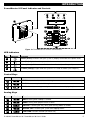
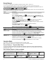
PowerMaster-10 Panel Indicator and Controls
1
2
3
20
4
5
6
7
9
10
12
8
11
13
14
15
16
17
18
19
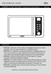
Figure 1a. PowerMaster-10 Controls and Indicators
LED Indicators
No.
Indication
Function
2
Power (Green): Indicates that your system is properly connected to the power outlet.
3
Arm (Red): Lights when the system is in the armed state.
4
Chime (Green): Chime zones will chime when disturbed (see Chapter 2).
5
Trouble (Orange): Lights when the system is in a state of trouble (see Chapter 3).
Control Keys
No.
Indication
Function
7
NEXT: Advance from item to item within a given menu.
8
BACK: Move one step back within a given menu.
9
OK: Review status messages one by one and also select a displayed option.
Arming Keys
No.
Indication
Function
12
AWAY: Arming when nobody is at home
10
HOME: Arming when people remain at home.
14
INSTANT: Canceling the entry delay upon arming (AWAY or HOME)
11
DISARM / OFF: Disarming the system and stopping alarms
16
PARTITION: Partition selection (for future use)
D-303223 PowerMaster-10 / PowerMaster-30 User's Guide
5
INTRODUCTION
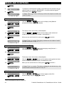
Other Keys
No.
Indication
Function
13
Chime ON/OFF
15
Reviewing the event log
17
Emergency (hold for 2 sec.)
18
Fire (hold for 2 sec.)
19
Press both buttons simultaneously for panic alarm
+
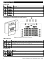
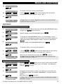
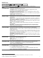
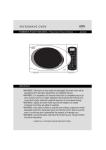
PowerMaster-30 Panel Indicator and Controls
Figure 1b. PowerMaster-30 Controls and Indicators
LED Indicators
No.
Indication
Function
2
Power (Green): Indicates that your system is properly connected to the power outlet.
3
Arm (Red): Lights when the system is in the armed state.
4
Chime (Green): Chime zones will chime when disturbed (see Chapter 2).
5
Trouble (Orange): Lights when the system is in a state of trouble (see Chapter 3).
Control Keys
No.
6
Indication
Function
7
NEXT: Advance from item to item within a given menu.
8
BACK: Move one step back within a given menu.
9
OK: Review status messages one by one and also select a displayed option.
D-303223 PowerMaster-10 / PowerMaster-30 User's Guide
INTRODUCTION
Arming Keys
No.
Indication
Function
12
AWAY: Arming when nobody is at home
10
HOME: Arming when people remain at home.
14
INSTANT: Canceling the entry delay upon arming (AWAY or HOME)
11
DISARM / OFF: Disarming the system and stopping alarms
16
PARTITION: Partition selection
Other Keys
No.
Indication
Function
13
Chime ON/OFF
15
Reviewing the event log
17
Emergency (hold for 2 sec.)
18
Fire (hold for 2 sec.)
19
Press both buttons simultaneously for panic alarm
+
20
PGM control
21
PGM output OFF
22
PGM output ON
23
Volume up *
24
Volume down *
25
Record message *
26
Play message *
27
Mute speaker * / **
* May not be functional on all versions of PowerMaster-30.
** The Mute Speaker button is active only if the "Set Voice Option" function is enabled ("enable prompts" - see
Chapter 6, section C.14).
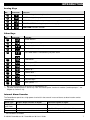
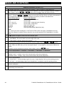
Internal Alarm Sounder
The PowerMaster panel has a high power siren built-in that sounds in case of alarm, to deter intruders and to
summon help.
Alarm Type
Burglar / 24
hour/ Panic
Fire
Test*
Graphic Representation of Signal
–––––––––––––––––––––––––––––––
Verbal Description of Signal
ON continuously
– – – – – – – – – – – – .................
–– (both external and internal sirens)
ON - ON - ON - pause - ON - ON - ON - pause.....
ON for 2 seconds (once)
* Not included in all models
D-303223 PowerMaster-10 / PowerMaster-30 User's Guide
7
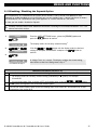
INTRODUCTION
General Audible Indicators
The sounds you will hear while using the control panel are:
Sound
Definition
Single beep, heard whenever a key is pressed
Double beep, indicates automatic return to the normal operating mode (by timeout).
Three beeps, indicates a trouble event
♫☺
♫
Happy Tune (- - - –––), indicates successful completion of an operation.
Sad Tune (–––––), indicates a wrong move or rejection
Other Audible Indicators∗
Pre-recorded voice announcements respond to your commands by announcing what the system is doing and by
prompting you to perform certain actions. They also announce alarms, troubles and identify the source of each
event.
Audible Indicators∗
The pre-recorded voice announcements respond to your commands by announcing what the system is doing
and by prompting you to perform certain actions. They also announce alarms, troubles and identify the source of
each event.
LCD Display
The display is a single line, backlit 16-character LCD used to display system status and events, time and date,
programming instructions and also an event log file which is accompanied by the date and time of each event.
The normal display alternates with the time and the system status, for example:
READY
HH:MM
(alternating)
READY MEMORY
Screen Saver Mode
For security reasons, it is sometimes required to hide the status indication (LCD and LED display) from a
potential intruder. If the Screen Saver option is enabled by the installer, then if no key is pressed for more than
30 seconds, the display will read “PowerMaster-10 / PowerMaster-30” and the LEDs will stop indicating any
status. Pressing any key will resume the normal status display. Pressing the Fire or Emergency keys will also
initiate the Fire or Emergency alarm.
If configured by the installer for additional security, the system will ask you to enter your user code as well
before resuming the normal display.
∗
8
Refers to PowerMaster-30 with voice option only
D-303223 PowerMaster-10 / PowerMaster-30 User's Guide
INTRODUCTION
Proximity Tags
Your system responds to valid proximity tags enrolled to the system. The proximity tag enables you to perform a
variety of functions without entering user code, for example, arming, disarming, reading the event log, etc.
Whenever the user code is required, you can simply present a valid proximity tag and perform the desired
operation without the need to key-in your user code.
When the system is disarmed, after presenting a valid proximity tag to the control panel, the message "<OK> for
button to immediately arm the control panel, or wait for 3
AWAY" is displayed. Now you can press the
second for system automatic AWAY arming (the message "Please exit now" will be displayed). Presenting the
proximity tag once again will DISARM the system.
Instead of pressing the
button (see above), you can press the
button once / twice (the
message "<OK> for HOME" / "<OK> for disarm" is displayed, accordingly) and then press the press
button for HOME arming / disarming.
Users and Codes
As a master User (User No.1) you will need a 4-digit security code to master the system (code 0000 is not
allowed).You can also authorize 7 other persons to use the system by providing them with their own security
codes (see Chapter 6, C.4 Programming User Codes).
Security codes are used mainly to arm and disarm the system or to access information that is restricted only to
authorized users (see Chapter 6, C.4 Programming User Codes).
Moreover, you can obtain up to 8 multi-function portable keyfob transmitters that will allow you and the other
users to easily arm, disarm and control the system without accessing the panel, including from outside the
premises (see Chapters 2 and 6, C.6 Add / Delete Keyfob Transmitters).
The Duress Code enables you to disarm the system using a special code that sends a silent alarm to the
monitoring station (See chapter 2).
D-303223 PowerMaster-10 / PowerMaster-30 User's Guide
9
OPERATING THE POWERMASTER SYSTEM
2. Operating the PowerMaster System
For more information regarding terms used in this chapter, refer to APPENDIX B. GLOSSARY.
Note: Except for specific reference to PowerMaster-30 functions, the buttons displayed throughout the User's
Guide are of the PowerMaster-10 control panel. When using the PowerMaster-30 control panel, these buttons
can be interchanged.
Basic Arming and Disarming
Following are a set of procedures for performing basic arming and disarming of the alarm system.
Partition selection process∗
Access to any desired partition is achieved through the use of an individual code or proximity tag. It is not
possible to access the INSTALLER MENU if one or more partitions are in the AWAY or HOME modes.
Before attempting to perform any operation on any given partition(s), it is necessary to perform the operations
below which enable you to select the desired/allowed partition(s) using the individual code or proximity tag:
PRESS
RESULTING DISPLAY
SELECT PARTITION
Enter partition # (1 - 3)
PARTITION 1
Note: The “Sad Tune” will be heard when attempting to select a partition to which no sensors / peripherals were
enrolled.
Preparing to Arm
Before arming, make sure that READY is displayed.
READY HH:MM
This means that all zones are secured and you may arm the system any way you choose.
If at least one zone is open (disturbed) the display will read:
NOT READY HH:MM
This means that the system is not ready for arming until all zones are secured (closed).
To review the open zones click
. The details and location of the first open zone detector (usually an
open door or window sensor) will be displayed.
To fix the open zone, locate the sensor and secure it (close the door or window) – see "device locator" below.
Each click of the
button will display another open zone or trouble indication.
Note: To quit at any stage and to revert to the "READY" display, click
.
Device Locator: The PowerMaster-10 / PowerMaster-30 system has a powerful device locator that helps you to
identify open or troubled devices indicated on the LCD display which operates as follows:
While the LCD displays an open or faulty device, the LED on the respective device flashes indicating "it's me".
The "it's me" indication will appear on the device within max. 16 seconds and will last for as long as the LCD
displays the device.
It is highly recommended to fix the open zone(s), thus restoring the system to the state of “ready to arm”. If you
do not know how to do this, consult your installer.
IMPORTANT! All arming procedures below are based on the assumption that quick arming has been enabled
by the installer. If quick arming is disabled, the PowerMaster-10 / PowerMaster-30 will prompt you to enter your
security code before arming as follows:
∗
Refers to PowerMaster-30 only
10
D-303223 PowerMaster-10 / PowerMaster-30 User's Guide
OPERATING THE POWERMASTER SYSTEM
ENTER CODE
____
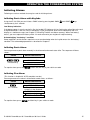
Arming ‘AWAY’
If the system is READY and quick arming is allowed, proceed as shown:
PRESS
RESULTING DISPLAY
ARMING AWAY
PLEASE EXIT NOW
Vacate the premises
↓
(Exit delay)
↓
AWAY
ARM indicator lights steadily during the armed state.
Arming ‘HOME'
If all perimeter zones are READY, and quick arming is allowed, proceed as shown:
PRESS
RESULTING DISPLAY
ARMING HOME
Move to interior zone
↓
(Exit delay)
↓
AWAY HH:MM
ARM indicator flashes during the armed state.
Disarming and Stopping Alarm
Enter the protected premises via a delayed zone. Upon detecting your entrance, the system will start sounding
the entry delay beeps alerting you to disarm the system before the entry delay ends. To disarm the system
proceeds as shown:
PRESS
RESULTING DISPLAY
CODE
[Enter Code]
____
Code
READY
HH:MM
ARM indicator extinguishes during the disarmed state.
Disarming the system also stops the siren alarm, irrespective of whether the alarm was initiated during the
armed or the disarmed state.
Disarming after an Alarm or Trouble
After disarming, different displays may appear indicating that the system is in a state of TROUBLE (TRBL) or
alarm MEMORY and will also sound trouble beeps
once per minute. To find out the troubles that have
been detected, or which zone alarmed, see Chapter 5. Reviewing Troubles and Alarm memory.
Upon eliminating the cause for trouble the TRBL display will disappear, the TROUBLE indicator will extinguish
and the trouble beeps will stop.
The MEMORY message will disappear only upon rearming the system.
IMPORTANT! If the trouble beeps bother you, disarm the system again (even though it is already disarmed).
This will cancel the trouble beeps for 4 hours.
D-303223 PowerMaster-10 / PowerMaster-30 User's Guide
11
OPERATING THE POWERMASTER SYSTEM
Special Arming & Disarming Options
In addition to basic arming, PowerMaster-10 / PowerMaster-30 provides you with several advanced arming and
disarming options:
Switching from ‘HOME’ to ‘AWAY’
. The response will be the same as in ARMING AWAY above.
Do not disarm the system - just press
Vacate the premises before the exit delay expires.
Switching from ‘AWAY’ to ‘HOME’
Do not disarm the system - simply press
. Since this operation reduces the security level, the
PowerMaster-10 / PowerMaster-30 will ask you to key in your master user code or user code, thus making sure
that you are an authorized user.
PRESS
[Enter code]
RESULTING DISPLAY
ENTER CODE
Code
____
ARMING HOME
Move to interior zone
↓ (Exit delay) ↓
ARM HOME HH:MM
ARM indicator flashes during the armed state.
Arming AWAY or HOME ‘Instant’
Pressing the
button during the exit delay will arm the system in the "Instant' mode, i.e. without an entry
delay. Therefore, any detection in any zone will trigger an immediate alarm.
If you wish to arm AWAY-INSTANT, proceed as follows.
PRESS
RESULTING DISPLAY
ENTER CODE
Code
____
ARMING AWAY
ARMING INSTANT
(alternating)
PLEASE EXIT NOW
Vacate the premises
↓ (Exit delay) ↓
AWAY
ARM indicator lights during the armed state.
Forced Arming AWAY or HOME
Forced arming allows you to arm the system even if one or more zones are disturbed and the "NOT READY"
message is displayed.
Automatic forced arming operates only if this option was enabled by the installer while programming your
system. All disturbed zones will be automatically bypassed - they will not be armed. The protected site will not
have maximum protection.
12
D-303223 PowerMaster-10 / PowerMaster-30 User's Guide
OPERATING THE POWERMASTER SYSTEM
Note: When forced arming is carried out, the buzzer “protests” by emitting a continuous tone during the exit
delay until the last 10 seconds of the delay. You can silence this signal by pressing the arming button again.
If forced arming is enabled and you wish to arm the system when NOT READY is displayed, proceed as shown:
PRESS
[Enter code]
RESULTING DISPLAY
ENTER CODE
Code
____
ARMING AWAY
PLEASE EXIT NOW
(to mute the buzzer)
Vacate the premises
(Exit delay)
↓
↓
AWAY
ARM indicator lights during the armed state.
Remember: Forced arming compromises security!!
Forced arming “HOME” is performed in a similar manner, as follows:
PRESS
[Enter code]
RESULTING DISPLAY
ENTER CODE
Code
____
ARMING HOME
PLEASE EXIT NOW
(to mute the buzzer)
↓
Go to interior zone
(Exit delay)
HOME
↓
HH:MM
ARM indicator flashes during the armed state.
Arming in the Latchkey Mode
This mode, if enabled by the installer, is useful for a parent at work who wants to be sure that his children have
returned from school and have disarmed the system. A special “latchkey” message will be sent out when the
system is disarmed by a “latchkey user”.
Latchkey users are holders of user codes 5 through 8 (PowerMaster-10) / user codes 23-32 (PowerMaster-30)
or users of Keyfob transmitters 5 through 8 (PowerMaster-10) / 23-32 (PowerMaster-30). The latchkey message
is considered an alert and not an alarm, and is therefore sent to the private telephones programmed by the user
as targets for alert messages.
Latchkey arming is possible only when you arm “AWAY”. To arm in the Latchkey mode, proceed as follows:
PRESS
RESULTING DISPLAY
ARMING AWAY
(Within 2 seconds)
ARMING LATCHKEY
(alternating)
PLEASE EXIT NOW
Vacate the premises
↓
(Exit delay)
AWAY
↓
D-303223 PowerMaster-10 / PowerMaster-30 User's Guide
13
OPERATING THE POWERMASTER SYSTEM
Note: Latchkey must be enabled by your installer.
ARM indicator lights during the armed state.
Disarming under Duress.
If you are forcibly compelled to disarm the system, enter the duress code (2580 by default) or another code set
by the installer. Disarming will take place normally but a silent alarm will be transmitted to the monitoring station.
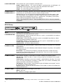
Using Keyfob Transmitters
Using portable keyfobs (KF-234 PG2) you can also conveniently arm and disarm the system from outside the
premises, initiate "panic alarms" and even use it as a remote control.- see figure 2.
The KF-234 PG2 commands are authenticated and encrypted using high security AES - 128 encryption
standard, hence malicious “code grabbing” is virtually impossible.
Arming & disarming with Keyfobs:
To arm or disarm the system press the respective key (see Figure 2). The keyfob will confirm with a red LED
blink and buzzer beep and will transmit your request to the panel.
ARM AWAY
ARM HOME
DISARM
AUX
Figure 2. KF-234 PG2 Keyfob Transmitter
If the operation is successfully completed, the green LED lights momentarily and a "happy tune" is heard. If the
operation cannot be completed, for example, when the system is "not ready", the red LED lights steadily and a
"sad tune" is heard.
Arming in Latchkey mode (*):
Pressing AWAY twice within 2 seconds initiates Latchkey arming, if enabled by the installer.
Using the AUX key ():
The AUX () key on the KF-234 PG2 keyfob can be configured by the installer to provide you with any of the
following options:
A. Arming the system in the INSTANT mode (*): This is the default option. Pressing the AUX () button
immediately after arming, during exit delay, will arm the system in "instant" mode. This means cancelling
the entry delay causing the system to trigger an immediate alarm upon entering the protected premises via
any zone. To prevent false alarms, you, and other keyfob holders, must disarm the system by pressing the
DISARM ( ) button on your keyfobs before entering the protected premises.
B. Not used: No function is assigned to the AUX () button
C. Stop Beeps: Pressing the AUX () button will cause the control panel and other devices in the system (such as
keyfobs, keypads, sirens etc.) to stop beeping (for example during exit or entry delays).
D.
E.
Skip exit delay: Pressing the AUX () button during the exit delay will immediately stop the exit delay
beeps.
Controlling a gate or another electrical device (PGM): Pressing the AUX () button opens/closes an
electrically-controlled gate, or controls a chosen electrical device via PGM output of the system.
(*) For further information - see Appendix B.
14
D-303223 PowerMaster-10 / PowerMaster-30 User's Guide
OPERATING THE POWERMASTER SYSTEM
Initiating Alarms
Following are various methods that may be used for initiating alarms.
Initiating Panic Alarm with Keyfobs
Using the KF-234 PG2 you can initiate a PANIC alarm by pressing both AWAY
simultaneously for 2 seconds.
and HOME
keys
Low Battery Indication
If the battery power is near the end of its life, the keyfob LED indicates this by flashing the yellow light at the end
of keyfob activation. It will also send a "low battery" signal to the panel which will be indicated on the LCD
display as a trouble message (see Chapter 5. Reviewing Troubles and Alarm memory). When "low battery"
occurs, you must replace the battery within 2-3 weeks otherwise your keyfob will stop functioning.
Acknowledging “low battery” condition
Some regulations and institutions require the user to acknowledge when the keyfob enters the “low battery”
condition. The acknowledge procedure is described in Chapter 6.
Initiating Panic Alarm
You can generate a panic alarm manually in the disarmed and armed states alike. The sequence will be as
shown:
PRESS
RESULTING DISPLAY
PANIC ALARM
simultaneously
READY HH:MM
To stop the alarm, press the
button and then key in your valid user code.
Initiating Fire Alarm
(This function is disabled in ACPO compliant version).
You can generate a fire alarm in disarmed & armed states, as follows:
PRESS
for 2 seconds
To stop the alarm, press
RESULTING DISPLAY
FIRE ALARM
Then, if or when the
system is in the disarmed
READY HH:MM
(alternating)
READY MEMORY
and then key in your valid user code.
D-303223 PowerMaster-10 / PowerMaster-30 User's Guide
15
OPERATING THE POWERMASTER SYSTEM
Initiating Emergency Alarm
You can generate a silent emergency alarm manually in the disarmed and armed states, as follows:
PRESS
for 2 seconds
RESULTING DISPLAY
EMERGENCY
Then, if or when the
system is in the disarmed
READY HH:MM
(alternating)
READY MEMORY
Siren Alarms
The maximum operating time of the siren is configured by the installer according to local regulations.
Continuously ON when initiated by a burglar zone or a 24-hour zone, and when a user initiates a “panic alarm”.
When initiated by a fire zone (smoke is detected) ON - ON - ON - pause - ON - ON - ON - pause - ........ and so
on.
If there is nobody around to disarm the system upon alarm, the siren will sound for the time duration set by the
installer - then will stop. If enabled, the strobe light will keep flashing until the system is disarmed or the siren will
stop as configured by the installer.
Chime ON/OFF
You can disable / enable the chime zones (see Appendix B) by alternate clicking of the
below:
PRESS
key, as shown
RESULTING DISPLAY
CHIME ON
CHIME OFF
↓
READY HH:MM
CHIME indicator lights steadily when “chime on” is selected.
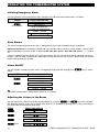
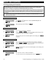
Adjusting the Volume of the Beeps
You can control the volume level of the sounded beeps by using the
and
keys on the keypad.
The following diagram shows how to increase the loudness of the beeps by clicking the <1> key (assuming that
the volume was at minimum to begin with).
PRESS
RESULTING DISPLAY
VOLUME+
VOLUME+
VOLUME+
(max)
16
VOLUME+
D-303223 PowerMaster-10 / PowerMaster-30 User's Guide
OPERATING THE POWERMASTER SYSTEM
The following diagram shows how to decrease the loudness of the beeps with the <4> key (assuming that the
volume was at maximum to begin with).
RESULTING DISPLAY
PRESS
(max)
VOLUME–
VOLUME–
VOLUME–
VOLUME–
D-303223 PowerMaster-10 / PowerMaster-30 User's Guide
17
SPEECH AND SOUND CONTROL
3. Speech And Sound Control∗
Speech & Sound Cont. Push-buttons
The sound and speech-related functions offered by the control panel are controlled with the keypad, as detailed
in the following list.
When partitioning is enabled:
Sound and speech-related features only apply to the partition(s) where the control panel is present. An activity
performed via the control panel from another partition will be displayed and the LED will light. The operation will
be added to the log file but will not be heard over the control panel speaker.
Key
Function
Increases the loudness of spoken messages
Decreases the loudness of spoken messages
Enables / disables the loudspeaker
Records a spoken message for other users of the alarm system
Allows listening to a recorded message left by another user of the alarm system
Enables / disables the chime function in chime zones
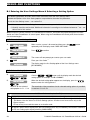
Adjusting the Speech Volume
The following diagram shows how to increase the loudness by clicking the <1> key (assuming that the volume
was at minimum to begin with).
PRESS
RESULTING DISPLAY
VOLUME+
VOLUME+
VOLUME+
(max)
VOLUME+
The following diagram shows how to decrease the loudness with the <4> key (assuming that the volume was at
maximum to begin with).
PRESS
RESULTING DISPLAY
(max)
VOLUME–
VOLUME–
VOLUME–
VOLUME–
∗
Refers to PowerMaster-30 with voice option only
18
D-303223 PowerMaster-10 / PowerMaster-30 User's Guide
SPEECH AND SOUND CONTROL
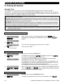
Voice ON/OFF
You can switch spoken announcements on and off by alternate clicking of the <7> key, as shown below.
RESULTING DISPLAY
PRESS
VOICE ON
VOICE OFF
↓
READY
HH:MM
Note: The system will maintain the “Voice OFF” state until subsequent selection of “Voice ON’.
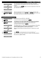
Message Exchange
For message exchange you can record a verbal message for other users of the alarm system. Face the panel,
press <2> and keep it pressed. When the display reads TALK NOW, start talking. The 5 dark boxes will slowly
disappear one by one, from right to left, as shown in the diagram below.
ACTION
RESULTING DISPLAY
(constant)
RECORD A MESSAGE
Talk ↓
TALK NOW
Talk ↓
TALK NOW
Talk ↓
TALK NOW
Talk ↓
TALK NOW
Talk ↓
TALK NOW
Stop talking
RECORDING ENDED
Once the last of the boxes disappears, RECORDING ENDED will be displayed.
When you release the button, the display will revert to the normal status-displaying mode, but will also indicate
that a message is waiting. For example:
READY
HH:MM
(alternating)
READY
MSG
To check your own message, listen to it within one minute from the end of recording (see the next section Message Playback). This way the MSG indication will not be erased.
Message Playback
To listen to a message left by another user of the system:
Click
and listen. PLAY will be displayed and the message will be played back over the built-in
loudspeaker. When the playback ends, the display will revert to the normal status-displaying mode. If more than
1 minute elapsed after recording, the MSG indication will disappear.
D-303223 PowerMaster-10 / PowerMaster-30 User's Guide
19
ELECTRICAL APPLIANCE CONTROL
4. Electrical Appliance Control
Control Options and Pushbuttons
The system allows manual or automatic remote control of a device connected to the PGM output.
The user defines the ON and OFF times via the Scheduler (see Chapter 6 - C.13 Programming the Scheduler).
The installer determines which zone sensors will switch the remote controlled appliances on and off. However,
the decision whether the remote controlled appliance will respond as programmed is up to you (see next
table).
Key
Function
Manual activation of a light or other household electrical appliance that is connected to PGM output.
Manual deactivation of a light or other household electrical appliance that is connected to PGM
output.
Selecting the active automatic control method:
Sensors: The appliance is controlled by sensors (assigned by the installer for this).
Timer: The appliance is controlled by timer (ON and OFF times are defined by the installer).
Both: The appliance is controlled by sensors as well as by a timer.
Examples of benefits gained by automatic remote control:
• Timer Control. When you are away, the timed activation / de-activation of an electrical appliance.
• Zone Control. Upon disturbance of a perimeter zone, the electrical device is switched on.
Note: Automatic activation and deactivation of electrical appliance depends also on the Scheduler setup (see
Chapter 6 - C.13 Programming the Scheduler).
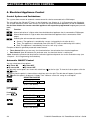
Automatic ON/OFF Control
You can select two of four options:
By Timer ON
By timer OFF
By sensor ON
By sensor OFF
The presently active options are shown with a dark box ( ) at the far right. To view the 2 other options click the
button.
A presently inactive option is shown without a dark box at the far right. The dark box will appear if you click
while the option is displayed. A “Happy Tune” indicates successful saving of a new option.
PRESS
RESULTING DISPLAY
BY TIMER ON
(If this is the default)
If not satisfied press
If satisfied press
BY TIMER OFF
BY TIMER OFF
BY TIMER OFF
BY SENSOR ON
(If this is the default)
20
D-303223 PowerMaster-10 / PowerMaster-30 User's Guide
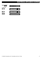
ELECTRICAL APPLIANCE CONTROL
If not satisfied Press
BY SENSOR OFF
If satisfied BY SENSOR OFF
BY SENSOR OFF
READY
HH:MM
D-303223 PowerMaster-10 / PowerMaster-30 User's Guide
21
REVIEWING TROUBLES AND ALARM MEMORY
5. Reviewing Troubles and Alarm memory
Alarm & Tamper Memory Indication
The PowerMaster-10 / PowerMaster-30 retains in its memory alarm and “tamper” events that occurred during
the last arming period.
Note: Alarm events are memorized only after the “abort period” (see Appendix B). This means that if you disarm
the system immediately - before the abort period expires - there will be no memory indication
A. Indication of Alarm & Tamper Condition
If the system is disarmed following an alarm event, a flashing MEMORY message will be displayed, as follows:
READY
HH:MM
(alternating)
READY MEMORY
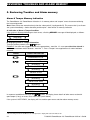
B. Displaying Alarm & Tamper Information
To review memory content, click
button.
EXAMPLE: An alarm was triggered because the garage door - zone No. 12 – was opened but then closed. In
addition, the bedroom motion detector - zone No. 7 - sent a “Tamper” message because its cover had been
removed.
PRESS
RESULTING DISPLAY
POWERMASTER-10∗
Z12 ALARMED
(alternating)
Z03 CONTACT
(alternating)
GARAGE DOOR
Z07 TAMPER-OPEN
(alternating)
Z06 MOTION SENS
(alternating)
BEDROOM
↓
READY
HH:MM
In response to additional clicking of the
button, the display shows details of other events retained in
open tamper (if any), or reverts to its initial state (see A above).
If the system is NOT READY, the display will first read the open zones and then alarm memory events.
∗
When working from the PowerMaster-30 control panel, the display will read "PowerMaster-30"
22
D-303223 PowerMaster-10 / PowerMaster-30 User's Guide
REVIEWING TROUBLES AND ALARM MEMORY
Clearing the Memory Indication
To clear the ‘Memory’ indication you must first review the cause of alarm as described above. Once you return
and enter the code if requested, then press Disarm
to the ‘Ready’ screen simply press Away
followed by the code. The memory message will now clear. Otherwise the memory indication and content will be
cleared upon the next arming of the system.
Troubles
A. Indication of Trouble condition
If the system detected a trouble condition in any of the enrolled devices, the TROUBLE indicator illuminates, 3
beeps are sounded once per minute and a flashing TRBL message is displayed, as follows.
READY
HH:MM
(alternating)
READY
TRBL
or, if the system is not ready for arming NOT READY
HH:MM
(alternating)
NOT READY
TRBL
B. Displaying Trouble Information
All trouble messages need to be reviewed and corrected as described below:
EXAMPLE: The kitchen device - zone No. 9 - has reported a low battery – the living room device zone No. 15 has been inactive, and an attempt to communicate a message to your telephone has failed. However, these
troubles do not prevent the system from being “ready to arm”.
To review the source of the current troubles one by one, click the
button repeatedly as shown below:
PRESS
RESULTING DISPLAY
POWERMASTER-10∗
Z09 LOW BATTERY
(alternating)
Z09 CONTACT
(alternating)
KITCHEN
↓
Z15 MISSING
(alternating)
Z15 MOTION SENS.
(alternating)
LIVING ROOM
↓
COMM. FAILURE
↓
READY HH:MM
∗
When working from the PowerMaster-30 control panel, the display will read "PowerMaster-30".
D-303223 PowerMaster-10 / PowerMaster-30 User's Guide
23
REVIEWING TROUBLES AND ALARM MEMORY
IMPORTANT! If the trouble beeps bother you, disarm the system again (even though it is already disarmed).
This will cancel the trouble beeps for 4 hours.
C. Reviewing Memory & Troubles at the Same Time
If alarms / tamper events are retained in the alarm memory and at the same time a state of trouble exists, the
display will first read the alarm memory followed by trouble events, as described in sections A & B above.
General Indications
After all trouble messages have been reviewed and if a SIM card is installed in the control panel, the
PowerMaster-10/PowerMaster-30 displays the GSM signal strength indication, as follows: "GSM RSSI
STRONG" / "GSM RSSI GOOD" / "GSM RSSI POOR".
If a PIR camera is enrolled in the system, the control panel will read "GPRS initialize" to indicate that the modem
is undergoing initialization. This message appears at the end of all trouble messages and immediately following
the GSM signal strength indication (if a SIM card is installed).
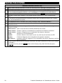
Correcting Trouble Situations
The trouble indications (illuminated TROUBLE indicator and flashing TRBL message) are cleared once you
eliminate the cause of trouble. The table below describes the system faults and respective corrective actions. If
you do not know how to correct a trouble situation, report it to your installer and seek his advice.
Fault
What it means
1-WAY
The device functions but cannot "hear" the panel. The control panel cannot configure
or control the device. Battery consumption increases.
AC FAILURE
There is no power supplied to the device.
CLEAN ME
The fire detector must be cleaned
COMM. FAILURE
A message could not be sent to the monitoring station or to a private telephone (or a
message was sent but was not acknowledged)
CPU LOW BATTERY
The backup battery within the control panel is weak and must be replaced (see
Chapter 10. Maintenance, "Replacing Backup Battery").
CPU TAMPER
The control panel was physically tampered with or its cover was opened, or it was
removed from wall.
FUSE TROUBLE
The PGM fuse is burnt out or overloaded.
GAS TROUBLE
Gas detector failure
GSM NET FAIL
The GSM communicator is not able to connect to the cellular network.
JAMMING
A radio-frequency signal which is blocking all communication frequency channels
between the sensors and control panel is detected.
LOW BATTERY
The battery of the indicated device is near the end of its useful life.
MISSING
A device or detector has not reported for some time to the control panel.
NOT NETWORKED
A device was not installed or not installed correctly, or, cannot establish
communication with the control panel after installation.
RSSI LOW
The GSM communicator has detected that GSM network signal is weak
SIREN AC FAILURE
There is no power to the siren
LINE FAILURE
There is a problem with the telephone line
24
D-303223 PowerMaster-10 / PowerMaster-30 User's Guide
MENUS AND FUNCTIONS
6. Menus and Functions
This chapter explains the user programming features of your PowerMaster-10 / PowerMaster-30 system and
allows you to tailor the PowerMaster-10 / PowerMaster-30 system according to your specific needs. The chapter
is divided into three sections, as follows:
Part A – Provides you with a general description of available User Setting options.
Part B – Guides you how to enter/exit the User Settings menu and how to select the desired setting options.
Part C – Guides you to execute the selected settings.
A The Settings You Need
The installer provides you with a ready-to-use alarm system, but a number of settings may still be needed. The
User Settings menu provides you with essential options that allow you to adapt the system to your specific
needs, to operate it as you desire and to upgrade it when necessary.
Below is a list of the User Settings menu options. A more detailed list is provided in section B.1. Detailed setting
instructions for options 1 to 14 are provided in sections C.1 to C.14.
1. Setting the zone bypass scheme(*)
2. Reviewing the zone bypass scheme(*)
3. Recalling the zone bypass scheme(*)
4. Programming user codes(**)
5. Add / delete proximity tags (**)
6. Add / delete keyfob transmitters (**)
7. Setting the time & time format(**)
8. Setting the date & date format(**)
9. Enabling / disabling auto-arming(**)
10. Setting the auto-arming time(**)
11. Programming private phone numbers(**)
12. Enabling / disabling the squawk option(**)
13. Programming the scheduler(**)
14. Enabling / disabling the voice option(**)
*
These menu options are available only if the bypass option was enabled by the installer.
** This option can be accessed only by the master user using the master user code.
Note 1: Although the user settings are your responsibility, you may request your installer to perform them for
you (except for the user codes which you desire to keep secret).
Note 2: Some options may not be available on your PowerMaster-10 / PowerMaster-30 system.
D-303223 PowerMaster-10 / PowerMaster-30 User's Guide
25
MENUS AND FUNCTIONS
B.1 Entering the User Settings Menu & Selecting a Setting Option
The following procedure describes how to enter and move within the User Settings menu.
Detailed descriptions of the User Setting options are provided at the end of the procedure.
To exit the User Settings menu – see section B.2.
1. You can enter the "User Settings" menu only when the system is disarmed.
2. Carefully read the section titled "Additional Information" according to the indicated references 1 etc – see
table at end of this section.
Note: Except for specific reference to PowerMaster-30 functions, the buttons displayed throughout the User's
Guide are of the PowerMaster-10 control panel. When using the PowerMaster-30 control panel, these buttons
can be interchanged.
A. To Enter the User Settings Menu
Make sure the system is disarmed and then press the
repeatedly until the display reads "USER SETTINGS". 1
1.
READY 00:00
2.
USER SETTINGS
Press
ENTER CODE: The screen will now prompt you to enter your user code.
CODE
Enter your User Code. 2
3.
SET BYPASS
button
to confirm
The display reads the first Setting option of the User Settings menu
[SET BYPASS]. 3
B. To Select a Setting Option
4.
SET BYPASS
or
5.
TIME & FORMAT
Continue to the selected
setting option in C.1 - C.14
Click the
or
button until the display reads the desired
setting option, for example, "TIME & FORMAT".
When the desired setting option appears on the display, press the
button to enter the setting process.
The remainder of the procedures for the selected setting options is provided
in sections C.1 to C.14.
Additional Information (section B.1)
1
2
3
26
Display shown in disarm state when all zones are secured (00:00 or other digits show present time).
a. If you have not already changed your personal code number, use the default setting – 1111.
b. The Master User has access to all User Settings options. All other users have access only to the
Bypass options.
c. Do not set any user code the same as an installer code.
The bypass options will be displayed in the User Settings menu only if enabled by the installer. Otherwise,
the first user setting option displayed will be [USER CODES].
D-303223 PowerMaster-10 / PowerMaster-30 User's Guide
MENUS AND FUNCTIONS
C. User Setting Options Menu
Click the
button.
button until the display reads the desired setting option and then press the
SET ZONE BYPASS
Use to set the Zone Bypass Scheme i.e. to bypass (exclude) faulty or
unsecured ("disturbed") zones, or to clear a bypassed zone (unbypass). For
further details and programming procedure see section C.1. 3
REVIEW BYPASS
Use to quickly review the Bypass Scheme i.e. which zones are bypassed. For
further details and reviewing procedure see section C.2. 3
RECALL BYPASS
Use to Recall the last used bypassed scheme for reuse in next arming period.
For further details and recalling procedure see section C.3. 3
USER CODES
Use to program your Master User secret access code and the seven codes of
the other users. For further details and programming procedure see section
C.4.
PROXIMITY TAGS
Use to add new Proximity Tags to or to delete Proximity Tags when lost. For
further details and programming procedure see section C.5.
KEYFOBS
Use to add new Keyfob Transmitters or to delete Keyfob Transmitters when
lost. For further details and programming procedure see section C.6.
TIME & FORMAT
Use to set the time clock to show the correct time and time format. For further
details and programming procedure see section C.7.
DATE & FORMAT
Use to set the calendar date to show the correct date and date format. For
further details and programming procedure see section C.8.
AUTO-ARM ENABLE
AUTO-ARM TIME
PRIVATE REPORT
SQUAWK
SCHEDULER
VOICE OPTION
<OK> TO EXIT
Returns to
first option
Use to enable or disable the Automatic Daily Arming option at predefined
times (see Auto-Arm Time setting). For further details and programming
procedure see section C.9.
Use to set the predetermined time for the Automatic Daily Arming if enabled
(see Auto-Arm Enable setting). For further details and programming
procedure see section C.10.
Use to program the four private telephone numbers for reporting alarm and
other event messages to private subscribers. For further details and
programming procedure see section C.11.
Use to enable or disable the squawk sound i.e. arm / disarm feedback
indication. For further details and programming procedure see section C.12.
Use to set the daily / weekly time schedule for start & stop activation of
devices connected to the PGM output. For further details and programming
procedure see section C.13.
Use to enable or disable the voice option i.e. the voice prompts that are heard
over the built-in loudspeaker. For further details and programming procedure
see section C.14.
Use to exit from the “USER SETTINGS” menu back to Main Menu. For further
details see section B.3.
D-303223 PowerMaster-10 / PowerMaster-30 User's Guide
27
MENUS AND FUNCTIONS
B.2 Returning to the Previous Step or Exiting the USER SETTINGS Menu
During the setting process it is frequently necessary to return to the previous setting step or option (i.e. "to go
one level up") or to exit the User Settings menu.
A. To Move One Level Up
To move one level up during the setting process, click the
one level up or to the previous setting step:
button once or more. Each click will take you
B. To Exit the USER SETTINGS Menu
Any screen
To exit "USER SETTINGS", move up the menu by pressing the
button
repeatedly (see above) until the display reads [<OK> TO EXIT] or preferably;
press the
button once which brings you immediately to the exit screen
[<OK> TO EXIT].
or
<OK> TO EXIT
When the display reads [<OK> TO EXIT], press
READY 12:00
The system exits the “USER SETTINGS" menu and returns to the normal disarm
state while showing the READY display.
B.3 Buttons used for Navigation & Setting
The keypad's buttons are used for various functions when programming. The following table provides a detailed
description of the function or use of each button.
Button
0-9
28
Definition
Navigation / Setting Function
NEXT
Use to move / scroll forward to the next menu options.
BACK
Use to move / scroll backward to the previous menu options.
OK
Use to select a menu option or to confirm a setting or action.
HOME
Use to move one level up in the menu or to return to previous setting step.
AWAY
Use to jump back to the [<OK> TO EXIT] screen to quit programming.
OFF
Use to cancel, delete, clear or erase setting, data, etc.
Numerical keypad used to enter numerical data.
D-303223 PowerMaster-10 / PowerMaster-30 User's Guide
MENUS AND FUNCTIONS
C.1 Setting the Zone Bypass Scheme
Bypassing permits arming only part of the system while allowing free movement of people within certain zones
when the system is armed.
It is also used to temporarily remove from service faulty zones that require repair work or to deactivate a sensor
if, for example, you are decorating a room.
♦ Here you can set the Zone Bypass Scheme i.e. to scroll through the list of registered (enrolled) sensors to
your PowerMaster-10 / PowerMaster-30 system and to Bypass (deactivate) faulty or disturbed sensors
(either READY or NOT-READY) or to Clear (reactivate) BYPASSED zones (sensors).
Once you have set a Bypass Scheme you can use the following 3 options:
>
To quickly review the bypassed zones – refer to section C.2.
>
To quickly clear a bypassed zone i.e. to reactivate the bypassed zone – refer to section C.2.
>
To repeat (recall) the last used zone bypassing scheme – refer to section C.3.
1. Zones will be bypassed throughout one disarm-arm period only. Disarming the system after arming will
suspend the entire bypassing scheme but you can recall and reuse it as described in section C.3.
2. Fire zones cannot be bypassed.
3. Carefully read the section titled "Additional Information" according to the indicated references 1 etc –
see table at end of section C.3.
REMEMBER – ZONE BYPASSING COMPROMISES SECURITY!
A. To Bypass a Zone
1.
SET ZONE BYPASS
Z01: READY
Enter the USER SETTINGS menu and select the [SET ZONE BYPASS] option
button to confirm. 1
and press the
The first zone, Z01, is displayed. 2
Living Room
2.
or
Z04: NOT READY
3.
Kitchen
4.
<OK> TO BYPASS
Click the
or
button until the display reads the zone you
wish to bypass (or clear bypass), for example, "Z04" for Zone 04. After
several seconds the LED on the respective device starts flashing indicating
"it's me".
When the display reads the zone you wish to bypass press
to
confirm.
The display now reads [<OK> TO BYPASS]. 3
To bypass the selected zone press
5.
Z04: BYPASSED
A "Happy Tune" ☺ sounds and the updated zone status is now displayed
i.e. [Z04: BYPASSED]. 5
D-303223 PowerMaster-10 / PowerMaster-30 User's Guide
29
MENUS AND FUNCTIONS
B. To Clear a Bypassed Zone
6.
Z04: BYPASSED
7.
Kitchen
<OFF> TO CLEAR
Repeat steps 1 to 2 above.
When the zone you wish to clear bypass appears on the display (for
to confirm. You can also identify the device
example, "Z04"), press
by looking for the "it's me" LED indication on the displayed device.
The display now reads [<OFF> TO CLEAR]. 3
To clear the bypassed zone press the
8.
Z04: READY
button.
A "Happy Tune" ☺ sounds and the updated zone status is now displayed,
i.e. [Z04: READY] or [Z04: NOT READY]. 6
C.2 Reviewing the Zone Bypass Scheme
♦ Here you can quickly review the Bypass Scheme i.e. the zones that are set to be bypassed during the next
arming session.
1.
REVIEW BYPASS
2.
BYPASS LIST
or
3.
Enter the USER SETTINGS menu and select the [REVIEW BYPASS] option
and press the
button to confirm. 1
The display reads [BYPASS LIST]
Click the
or
buttons repeatedly to review all bypassed
zones in ascending numerical order. When done, click the
button to
exit. 6
Z04: BYPASSED
Kitchen
C.3 Recalling the Zone Bypass Scheme
♦ Use this option to repeat (recall) the most recent Bypassed Scheme for use during the next arming session.
1.
RECALL BYPASS
Enter the USER SETTINGS menu, select the [RECALL BYPASS] option and
press the
button to confirm. 1
2.
<OK> TO RECALL
The display now reads [<OK> TO RECALL]. 4
To recall the last used bypass scheme press
3.
Bypass RECALLED
☺ Return to step 1
30
.
A "Happy Tune" ☺ sounds. The display reads [Bypass RECALLED] and
then returns to “USER SETTINGS" step 1. 6
D-303223 PowerMaster-10 / PowerMaster-30 User's Guide
MENUS AND FUNCTIONS
Additional Information (section C.1 – C.3)
1
2
For detailed instructions on how to select User Settings – refer to section B.1 and section B.2.
a. The STATUS to the right of the zone number indicates whether the zone is READY, NOT-READY or
BYPASSED.
b. In the example on the left the display reads [Z01: READY] alternating with [Living Room].
3
a. If the zone you selected is "not bypassed", the display prompts you to press [<OK> TO BYPASS].
However, if the zone you selected is already "bypassed", the display prompts you to press [<OFF> TO
CLEAR].
b. To abort and return to the previous step press
4
5
6
or
The display now prompts you to press [<OK> TO RECALL] i.e. to repeat the last used bypass scheme. If
you wish to abort and return to the User Setting menu, press
.
You can now repeat steps 2 - 5 to bypass or clear another zone. To end this session and to select other
menu options or to quit programming - follow the instructions in section B.2.
You can now select another option in the User Setting menu (see section B.1), or quit programming (see
section B.2).
D-303223 PowerMaster-10 / PowerMaster-30 User's Guide
31
MENUS AND FUNCTIONS
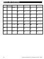
C.4 Programming User Codes
The PowerMaster-10 / PowerMaster-30 system allows you to authorize up to 8 people (in PowerMaster-10
system) / 48 people (in PowerMaster-30 system) to arm and disarm the system by providing each with a unique
4 digit personal security code, and assigning them with different security levels and functionalities. There are
two types of users: Master User and User, The table below summarizes the different operations that can be
performed by different users:
User type
Master User
User
Function
Arm/disarm
Zone bypass
Authorize 7 other user codes
Set user codes
Report to private
Enroll/delete keyfob
Automatic arming
Enable squawk
Set date and time format
Read event log
Arm/disarm
Zone bypass options
The user codes are assigned as follows:
User Code 1 is assigned to the Master User of the system (i.e. the owner). It is the only user code that allows
access to the User Setting menu. The default setting of the Master User code 1 is 1111. This code cannot be
erased and must be replaced with a secret code as soon as possible.
User Codes 2-4 (PowerMaster-10) / User Codes 2-22 (PowerMaster-30) are assigned to family members,
co-workers etc. They enable arming and disarming of the system or of selected partitions as defined by the
Master User. They can access the "User Setting" menu only for "zone bypassing" provided this option is
enabled in the Installer menu.
User Codes 5-8 (PowerMaster-10) / User Codes 23-32 (PowerMaster-30) are the same as user codes 2-4 /
2-22 but can be assigned to "Latchkey" (child monitor) users. For a detailed explanation of the Latchkey
application see Chapter 2 (Arming in the Latchkey Mode) and Appendix B.
Partition Option (For information about Partition option - see Appendix A) – not applicable to PowerMaster-10
Your PowerMaster-30 system can divide zones into up to 3 parts (groups) via the installer menu. These parts
are designated as partitions P1, P2 & P3. Each partition can be armed and disarmed separately providing
protection to selected parts of the premises.
Each user out of the 48 system users can be authorized by the Master User to arm and disarm any combination
of partitions including all 3 partitions.
♦ Here you can program (or edit) the 48 User Codes and thereby define which of these will be authorized to
arm and disarm.
1. The default setting 1111 of Master User Code 1 is the same for all PowerMaster-10 / PowerMaster-30
systems and is known to many other people. Therefore, we highly recommend that you immediately
replace it with a unique secret code. Never set any user code the same as any installer code.
2. Code "0000" is not valid! Do not use it.
3. The duress code (2580 by default), which is set in the installer menu, cannot be selected as a normal
user code. Any attempt to program it will be rejected by the system.
4. Carefully read the section titled "Additional Information" according to the indicated references 1 etc –
see table at end of this section.
32
D-303223 PowerMaster-10 / PowerMaster-30 User's Guide
MENUS AND FUNCTIONS
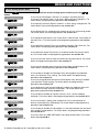
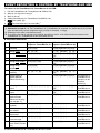
A. To Program a User Code
1.
USER CODES
2.
User 01 Code or
3.
User 26 Code 4.
User 26 : 5327
Enter the USER SETTINGS menu, select the [USER CODES] option and
button to confirm. 1
press the
The first user code "User 01 Code" is displayed. 2
At the blinking cursor position, key in the User Code you wish to program ,
for example, [2+6] for user code 26, or alternatively click the
or
button until the display reads, "User 26 Code".
When the user code you wish to program appears on the display, press
to confirm.
To program or edit the code, at the blinking cursor position enter the 4 digit
code, for example, “1234”, using the numerical keypad. 3, 4
When done, press
5.
User 26 5327
to confirm.
A "Happy Tune" ☺ sounds. The display confirms the saved code. 5, 6
☺ Return to step 3
B. To Set Partitions Authorization∗
6.
SET PARTITIONS
7.
U26: P1 P2 P3
U26: P1 P2 P3
The display will read [SET PARTITIONS]. 7
Use the keypad keys
,
,
partitions P1, P2 & P3, respectively. 8
When you are satisfied with the setting, for example, User 4 is authorized
with Partition 1 and 3 only, press
☺ Return to step 3
∗
to change the status of the
to confirm.
A "Happy Tune" ☺ sounds. The display confirms the Partition setting. 9
Refers to PowerMaster-30 only
D-303223 PowerMaster-10 / PowerMaster-30 User's Guide
33
MENUS AND FUNCTIONS
Additional Information (section C.4)
1
2
3
For detailed instructions on how to select the setting options – refer to section B.1 and section B.2.
The display shows the 1st User Code (Master User) in the list of 8 User Codes (in PowerMaster-10
system) / 48 User Codes (in PowerMaster-30). If you have not yet changed the default code 1111, we
recommend that you change it now.
a. The display shows the user code currently programmed in this location (e.g. 5327).
b. The cursor blinks on the first digit of the code.
c. If the location is free the display will be blank ( - - - - ).
4
5
You can move the cursor to the next or previous digit using the (
/
button erases the digit of the cursor + all digits right of the cursor.
) buttons. Pressing the
a. The new code is momentarily displayed without the cursor before reverting to step 3.
b. If Partition is enabled, continue to step 6.
6
7
8
9
34
You can now repeat steps 3 - 5 to program or edit another user code. To end this session and to select
other menu options or to quit programming – follow the instructions in section B.2.
This setting can be performed only after completing steps 1 - 5 of section C.4A.
The symbol now appears next to the newly selected Partitions.
You can now repeat steps 3 - 7 to program or edit another user code.
D-303223 PowerMaster-10 / PowerMaster-30 User's Guide
MENUS AND FUNCTIONS
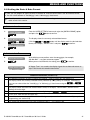
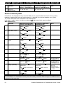
C.5 Add / Delete Proximity Tags
Each of the 8 PowerMaster-10 / PowerMaster-30 users may be provided with a proximity tag that can be used
instead of the user codes to perform a variety of functions, for example, arming, disarming, reading the event
log, etc.
Whenever a user code is required you can simply present a valid proximity tag instead of entering the user
code. Each tag should be assigned with a serial No. 1-8 (PowerMaster-10) / 1-32 (PowerMaster-30) that
corresponds to the User Code No. 1-8 (PowerMaster-10) / 1-32 (PowerMaster-30) and enrolled into the system
correspondingly.
The partition∗ authorization of the tags is identical to their corresponding user codes. For example, proximity tag
3 is assigned to user code 3.
♦ Here you can add (enroll) new proximity tags or delete tags as required.
Carefully read the section titled "Additional Information" according to the indicated references1 etc – see
table at end of this section.
A. To Add (Enroll) a Proximity Tag
1.
PROXIMITY TAGS
2.
ADD NEW TAG
3.
DEVICE ENROLLED
☺ Go to step 5
5.
The display will read [ADD NEW TAG]. 3
To begin the process of enrolling a new proximity tag press
.
ENROLL NOW or
ENTR ID:xxx-xxxx
4.
Enter the USER SETTINGS menu, select the [PROXIMITY TAGS] option and
press the
button to confirm. 1
T01:Tag (Prox)
Present the proximity tag to the control panel within the timeout period.
If enrollment was successfully completed, a "Happy Tune" ☺ sounds and
the display reads [DEVICE ENROLLED] for a short duration and then changes
to read the tag's details. 4
The display shows the allocated tag serial No (user No.), which is always the
first free number, for example:
[T01:Tag (Prox)].
or
T05:Tag (Prox)
☺ Return to step 2
∗
If you wish to assign the tag to another user, for example, "User No. 5", key
or
button until the display
in [0+5] or alternatively click the
reads [T05:Tag (Prox)] and then press
to confirm.
The display reads [DEVICE ENROLLED] a "Happy Tune" ☺ sounds and the
display will then change to [T01:Tag (Prox)]. 7
Refers to PowerMaster-30 only
D-303223 PowerMaster-10 / PowerMaster-30 User's Guide
35
MENUS AND FUNCTIONS
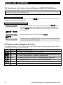
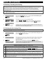
B. To Delete a Proximity Tag
1.
PROXIMITY TAG
2.
ADD NEW TAG
Enter the USER SETTINGS menu, select the [PROXIMITY TAG] option and
press the
button to confirm. 1
The display will read [ADD NEW TAG].
Click the
3.
DELETE TAG
T01:Tag (prox)
4.
or
Press
button until the display reads [DELETE TAG].
to confirm.
The display will read [T01:Tag (prox)] alternating with the ID number of the
tag. 2, 5
Key in the tag number you wish to delete, for example, [0+6] or alternatively
click the
or
button until the display reads the tag number,
"T06:Tag (prox)" and "ID No. 300-2564".
K06:Tag (prox)
When the tag you wish to delete appears on the display, press
.
5.
<OFF> to delete
The display now reads [<OFF> to delete].
To delete the tag press the
6.
DELETE TAG
☺ Go to step 3
6
button.
A "Happy Tune" ☺ sounds and the display reads [DELETE TAG] and
returns to step 3. 8
Additional Information (section C.5)
1
2
3
4
5
6
7
8
36
For detailed instructions on how to select User Settings – refer to section B.1 and section B.2.
The display shows the 1st Tag (Tag No.1) of the 8 tags.
To abort enrollment press the
button.
If the tag was previously enrolled in the system, the PowerMaster-10 / PowerMaster-30 display reads
"ALREADY ENROLLED" and then switches to the name of the tag alternating with its ID number.
If no proximity tag is enrolled in the system, the display reads "NO EXISTING DEV.".
If you wish to abort the procedure, press the
button.
You can now enroll another proximity tag. You can also select another option in the User Setting menu
(see section B.1 and section B.2), or quit programming (see section B.3).
You can now add or delete another proximity tag. You can also select another option in the User Setting
menu (see section B.1 and section B.2), or quit programming (see section B.3).
D-303223 PowerMaster-10 / PowerMaster-30 User's Guide
MENUS AND FUNCTIONS
C.6 Add / Delete Keyfob Transmitters
Each of the 8 PowerMaster-10 / PowerMaster-30 users may be provided with a portable keyfob transmitter to
exercise better, quicker and safer arming/disarming and other control functions. Each keyfob should be
assigned with a serial No. 1-8 (PowerMaster-10) / 1-32 (PowerMaster-30) and enrolled into the system
correspondingly.
Partition Option∗ (For information about Partition option - see Appendix A)
If the Partition option is enabled in the control panel, each of the 32 keyfobs can be authorized by the Master
User to arm and disarm any combination, or all 3 partitions, irrespective of the authorization of its corresponding
user code.
♦ Here you can add (enroll) the 8 (PowerMaster-10) / 32 (PowerMaster-30) Keyfob transmitters and define
which of the 3 partitions∗ each of the keyfob will be authorized to arm and disarm, or delete keyfobs as
required.
1. Before anything else, gather up all keyfob units you intend to enroll and make sure they all have
batteries installed and that they are active (the LED blinks upon pressing any of the buttons).
2. Carefully read the section titled "Additional Information" according to the indicated references1 etc –
see table at end of this section.
A. To Add (Enroll) a Keyfob
1.
KEYFOBS
2.
ADD NEW KEYFOB
3.
ENROLL NOW or
ENTR ID:xxx-xxxx
4a.
DEVICE ENROLLED
☺ Go to step 5
4b.
ID No. 300-5786
ID ACCEPTED
☺ Go to step 5
5.
F01:keyfob
Enter the USER SETTINGS menu, select the [KEYFOBS] option and press
button to confirm. 2
the
The display will read [ADD NEW KEYFOB]. 4
To enroll a new keyfob press
.
The display offers you two alternative methods to enroll a keyfob:
A: ENROLL NOW: Press and hold the AUX button on the selected keyfob
until the LED is constantly on. 1 This procedure completes the enrollment.
If enrollment was successfully completed, a "Happy Tune" ☺ sounds and
the display reads [DEVICE ENROLLED] for a short duration and then changes
to read the keyfob's details. Continue to step 5. 5
B: ENTER ID (Pre-enrollment): Enter the 7-digit number that appears on
to confirm. To complete the
the keyfob sticker and then press
enrollment procedure see note 6 in the Additional Information table below. 7
If a valid ID was entered, a "Happy Tune" ☺ sounds and the display reads
[ID ACCEPTED] for a short duration and then changes to read the keyfob's
details. Continue to step 5.
The display shows the allocated keyfob serial No (user No.), which is always
the first free number, and the keyfob's ID number; for example:
[F01:Keyfob] alternating with [ID No. 300-5786].
ID No. 300-5786
or
∗
If you wish to assign the keyfob to another user, for example, "User No. 5", ",
Refers to PowerMaster-30 only
D-303223 PowerMaster-10 / PowerMaster-30 User's Guide
37
MENUS AND FUNCTIONS
F25:keyfob
☺ Return to step 2
key in [2+5] or alternatively click the
or
display reads [F25:Keyfob] and then press
button until the
to confirm.
The display reads [DEVICE ENROLLED] or [ID accepted] if the keyfob was
enrolled manually by entering the ID number, a "Happy Tune" ☺ sounds
and the display will then change to [F01:Keyfob].
B. To Delete a Keyfob
1.
KEYFOBS
2.
ADD NEW KEYFOB
Enter the USER SETTINGS menu, select the [KEYFOBS] option and press
the
button to confirm. 2
The display will read [ADD NEW KEYFOB].
Click the
3.
DELETE KEYFOB
F01:keyfob
4.
or
Press
button until the display reads [DELETE KEYFOB].
to confirm.
The display will read [F01:Keyfob] alternating with the ID number of the
keyfob. 3
Key in the keyfob number you wish to delete, for example, [0+6] or
alternatively click the
or
button until the display reads the
keyfob number, for example, "F06:Keyfob" and "ID No. 300-5799".
F06:keyfob
When the keyfob you wish to delete appears on the display, press
.5
ID No. 300-5799
5.
<OFF> TO DELETE
The display now reads [<OFF> TO DELETE]. 6
To delete the keyfob press the
6.
button.
☺ Go to step 3
DELETE KEYFOB
38
A "Happy Tune" ☺ sounds and the display reads [DELETE KEYFOB] and
returns to step 3. 8
D-303223 PowerMaster-10 / PowerMaster-30 User's Guide
MENUS AND FUNCTIONS
Additional Information (section C.6)
1
2
3
4
5
5
6
7
The LED will extinguish after several seconds. In case of difficulties in communication with the control
panel, the LED may blink for several seconds more while trying to establish communication. During this
period of time the keyfob keys are disabled.
For detailed instructions on how to select User Settings – refer to section B.1 and section B.2.
The display shows the 1st Keyfob (Keyfob No.1) of the 8 keyfobs.
To abort enrollment press the
button.
If the keyfob was previously enrolled in the system, the PowerMaster-10 / PowerMaster-30 display reads
"ALREADY ENROLLED" and then switches to the name of the keyfob alternating with its ID number.
Before you delete a keyfob, identify the keyfob either by the keyfob No., for example, F06, or by the ID
number of the keyfob that appears on the display, and then make sure that it is the keyfob you wish to
delete.
If you regret and wish to abort the procedure, press the
Pre-Enrollment Procedure:
button.
Step 4b enables you to register the device ID and to complete the programming process without being in
possession of the device itself (can also be performed off-site by the installer). Enrollment can then be
completed at a later stage by following the same enrollment procedure described in Step 3 without
entering the User Settings menu.
8
You can now delete another keyfob, select another option in the User Setting menu (see section B.1 and
section B.2), or quit programming (see section B.3).
D-303223 PowerMaster-10 / PowerMaster-30 User's Guide
39
MENUS AND FUNCTIONS
C.7 Setting the Time & Time Format
♦ Here you can program or adjust the built-in-clock to show the correct time in the desired time format.
♦ You can select between a 24 hour and a 12 hour (AM/PM) time format.
Carefully read the section titled "Additional Information" according to the indicated references1 etc – see
table at end of this section.
A. To Set the Time Format
1.
TIME & FORMAT
2.
US FORMAT-12H
or
EU FORMAT-24H
Enter the USER SETTINGS menu and select the [TIME & FORMAT] option
and press the
button to confirm. 1
The display shows the currently selected time format. 2
Click the
or
button until the display shows the desired time
format, for example, "EU FORMAT-24H" and press
to confirm .
3.
B. To Set the Time 5
4.
TIME
12:40P
5.
TIME 08:55A
☺ Return to step 2
At the blinking cursor position, enter the correct time, for example, “8:55A”,
using the numerical keypad. 4
When you are satisfied with the setting, press
to confirm.
A "Happy Tune" ☺ sounds, the display reads the set time, returns to step
2 and then reads the selected time format. 6, 7
Additional Information (section C.7)
1
2
For detailed instructions on how to select User Settings – refer to section B.1 and section B.2.
a. The display shows the currently selected format (indicated by a symbol), for example, "24 Hrs".
b. You can now select either the 12 Hrs or 24 Hrs time format using the
3
4
5
6
7
40
or
buttons.
The display shows the Time in the selected Time Format, for example, "12:40 PM", with the cursor
blinking on the first hour digit "1". The letter that follows the displayed time indicates one of the following:
"A" = AM; "P" = PM and "none" for 24 Hrs time format.
When the curser is positioned on the AM/PM digit, you can set to "AM" with the
button and the
"PM" with the
button
You can move the cursor to the next or previous digit using the
or
buttons.
This setting can be performed only after completing steps 1 – 3 of section C.7A.
The time saved is displayed without the cursor, for example, "08:55 A" followed by the selected time
format.
You can now select another option in the User Setting menu (see section B.1 and section B.2), or quit
programming (see section B.3).
D-303223 PowerMaster-10 / PowerMaster-30 User's Guide
MENUS AND FUNCTIONS
C.8 Setting the Date & Date Format
♦ Here you can program or adjust the built-in-calendar to show the correct date in the desired date format.
♦ You can select between a "mm/dd/yyyy" and a "dd/mm/yyyy" date format.
Carefully read the section titled "Additional Information" according to the indicated references1 etc – see
table at end of this section.
A. To Set the Date Format
1.
DATE & FORMAT
2.
DATE MM/DD/YYYY
or
DATE DD/MM/YYYY
Enter the USER SETTINGS menu and select the [DATE & FORMAT] option
and press the
button to confirm. 1
The display shows the currently selected date format. 2
Click the
or
button until the display reads the desired date
to confirm.
format, for example, "DD/MM/YYYY" and press
3.
B. To Set the Date 7
4.
Date:20/04/2011
5.
DATE 20/02/2008
☺ Return to step 2
At the blinking cursor position, enter the correct date, for example,
“20.04.2011”, using the numerical keypad. 3, 4, 5
When you are satisfied with the setting, press
to confirm.
A "Happy Tune" ☺ sounds, the display shows the set date and returns to
step 2 and shows the selected date format. 6
Additional Information (section C.8)
1
2
For detailed instructions on how to select User Settings – refer to section B.1 and section B.2.
The display shows the currently selected format (indicated by a symbol), for example, "mm/dd/yyyy".
You can now select either the "mm/dd/yyyy" or "dd/mm/yyyy" date format using the
button.
3
4
5
6
7
or
The display shows the Date and selected Date Format, for example, "30.12.2007", with the cursor
blinking on the first digit.
You can move the cursor to the next or previous digit using the
or
button.
For the year, enter the two last digits only.
You can now select another option in the User Setting menu (see section B.1 and section B.2), or quit
programming (see section B.3).
This setting can be performed only after completing steps 1 – 3 of section C.8A.
D-303223 PowerMaster-10 / PowerMaster-30 User's Guide
41
MENUS AND FUNCTIONS
C.9 Enabling / Disabling Auto-Arming
The PowerMaster-10 / PowerMaster-30 system can be programmed to automatically arm itself on a daily basis
at a predetermined time. This feature is useful especially in commercial applications, such as in stores, to
ensure that the system is always armed and without having to assign security codes to employees.
♦ Here you can enable (activate) and disable (stop) the Auto-Arming. To set the Auto-Arming time –
see section C.10.
Carefully read the section titled "Additional Information" according to the indicated references1 etc – see
table at end of this section.
1.
AUTO-ARM ENABLE
2.
disable autoarm
or
Enter the USER SETTINGS menu, select the [AUTO-ARM ENABLE] option
and press the
button to confirm. 1
The display shows the currently selected setting. 2
Click the
or
button until the display reads the desired
setting, for example, "enable autoarm" and press
to confirm.
enable autoarm
3.
☺ Return to step 1
A "Happy Tune" ☺ sounds. The display confirms the saved setting, and
then returns to the User Setting menu, step 1. 3
C.10 Setting the Auto-Arming Time
♦ Here you can program the exact time of the Auto-Arming.
1.
AUTO-ARM TIME
2.
arm time 12:00P
Enter the USER SETTINGS menu, select the [AUTO-ARM TIME] option and
press the
button to confirm. 1
The display shows the current setting of the Auto-Arm Time. At the blinking
cursor position, enter the correct time, for example, “8:30A”, using the
numerical keypad. 4
When you are satisfied with the setting, press
3.
TIME 08:30A
☺ Return to step 1
to confirm.
A "Happy Tune" ☺ sounds. The display confirms the saved time, then
returns to the User Setting menu, step 1. 5, 6
Additional Information (section C.9 - section C.10)
1
2
3
4
5
6
42
For detailed instructions on how to select User Settings – refer to section B.1 and section B.2.
The display shows the current setting (indicated by a symbol), for example, "disable autoarm". You
can now select either to enable or disable auto-arming using the
or
button.
The symbol now appears next to the newly selected option.
The display shows the current setting of the Auto-Arm Time, for example, "12:00 PM", with the cursor
blinking on the first hour digit "1". For detailed explanation of how to set the time - refer to Section C.7 B.
The saved auto arm time is displayed without the cursor, for example, "08:30 A".
You can now select another option in the User Setting menu (see section B.1 and section B.2), or quit
programming (see section B.3).
D-303223 PowerMaster-10 / PowerMaster-30 User's Guide
MENUS AND FUNCTIONS
C.11 Programming Private Phone and SMS Reporting
The PowerMaster-10 / PowerMaster-30 system can be programmed to send various event notification
messages such as alarm, arming or trouble events, to 4 private telephone subscribers by audible signal and if a
GSM option is installed, also to 4 SMS telephone numbers. These reports can be programmed either instead of
or in addition to the reports transmitted to the monitoring company.
Further details about the event notification by telephone and by SMS are provided in Chapter 7. Event
Reporting and Control by Telephone and SMS.
You can also determine the number of times the private telephone number is dialed and whether a single
acknowledge signal will stop the reporting process or an acknowledge signal from each telephone will be
required before the current event is considered reported.
Here you can program:
The specific events you wish the system to report.
The 1st, 2nd, 3rd, and 4th private telephone and SMS numbers for reporting alarm and other event messages to
private subscribers.
The number of redial attempts, two-way voice communication∗, and whether to use a single acknowledge signal
or an acknowledge signal from each telephone before the current event is considered reported.
Carefully read the section titled "Additional Information" according to the indicated references1 etc – see
table at end of this section.
VOICE REPORT
A. To Program Events to be Reported by private telephone
1.
PRIVATE REPORT
2.
VOICE REPORT
3.
REPORTED EVENTS
disable report 4.
or
alarms
5.
alarms
☺ Return to step 3
Enter the USER SETTINGS menu and select the [PRIVATE REPORT] option
button to confirm. 1
and press the
The display will read [VOICE REPORT] which is the first option used to
enable Private Reporting, to determine which events will be reported and to
program private telephone numbers.
To enter this option press
.
When the display reads [REPORTED EVENTS] press
.2
The display shows the currently selected option.
Click the
or
button until the display reads the event group
you wish to be reported via private phones, for example, [alarms]. 3
When you are satisfied with the setting, press
to confirm.
A "Happy Tune" ☺ sounds. The display confirms the set events to be
reported, and returns to step 3. 4, 12
B. To Program a Private Phone
6.
REPORTED EVENTS
or
7.
∗
or
button until the display reads the desired
Click the
Telephone No. you wish to program or edit, for example, "2nd private
tel#", and press
to confirm.
2nd private tel#
Refers to PowerMaster-30 with voice option only
D-303223 PowerMaster-10 / PowerMaster-30 User's Guide
43
MENUS AND FUNCTIONS
8.
032759333
To program or edit the phone number, at the blinking cursor position enter the
phone number, for example, “8032759333”, using the numerical keypad. 5, 6
When done, press
9.
8032759333
☺ Return to step 7
to confirm.
A "Happy Tune" ☺ sounds, the display confirms the telephone number and
returns to step 7. 7, 12
C. To Program the Number of Redial Attempts
10.
2nd private tel#
or
11.
button until the display reads [Redial
to confirm.
Redial attempts
3 attempts
12.
Click the
or
attempts] and press
or
4 attempts
The display shows the currently selected option.
Click the
or
button until the display reads the desired
number of redial attempts, for example, "4 attempts". 8
When you are satisfied with the setting, press
13.
4 attempts
☺ Return to step 11
to confirm.
A "Happy Tune" ☺ sounds. The display confirms the set number of redial
attempts and returns to step 11. 4, 12
D. To Program two-way voice communication∗
14.
Redial attempts
or
15.
or
>private] and press
button until the display reads [Voice<- to confirm.
Voice<- ->private
enable two-way 16.
Click the
or
disable two-way
The display shows the currently selected option.
Click the
or
button until the display reads the desired voice
communication method, for example, "disable two-way". 9
When you are satisfied with the setting, press
17.
disable two-way
☺ Return to step 15
to confirm. 4
A "Happy Tune" ☺ sounds. The display confirms the desired two-way voice
communication method and returns to step 15. 4, 12
E. To Program the Acknowledge Method
18.
Voice<- ->private
or
∗
Click the
or
acknowledge] and press
button until the display reads [Tel.
to confirm. 11
Refers to PowerMaster-30 with voice option only
44
D-303223 PowerMaster-10 / PowerMaster-30 User's Guide
MENUS AND FUNCTIONS
19.
Tel. acknowledge
by single ack
20.
or
by all ack
The display shows the currently selected option.
Click the
or
button until the display reads the desired
acknowledge method, for example, "by all ack". 10
21.
all ack
☺ Return to step 19
A "Happy Tune" ☺ sounds. The display confirms the set acknowledge
method and returns to step 19. 4, 12
SMS REPORT
A. To Program Events to be Reported by SMS
1.
PRIVATE REPORT
2.
VOICE REPORT
3.
SMS REPORT
4.
REPORTED EVENTS
disable report 5.
or
alarms
6.
alarms
☺ Return to step 4
Enter the USER SETTINGS menu and select the [PRIVATE REPORT] option
and press the
button to confirm. 1
When the display reads [VOICE REPORTS] press
.
The display will read [SMS REPORT] which is the second option used to
enable the Private Reporting, to determine which events will be reported via
SMS and to program SMS telephone numbers. To enter this option press
.
When the display reads [REPORTED EVENTS] press
.
The display shows the currently selected option. 3
Click the
or
button until the display reads the event group
you wish to be reported via SMS, for example, [all -alerts]. 4
When you are satisfied with the setting, press
to confirm.
A "Happy Tune" ☺ sounds. The display confirms the set events to be
reported, and returns to step 4. 4, 12
B. To Program SMS Telephone Numbers
7.
REPORTED EVENTS
or
8.
2nd SMS tel#
9.
080168593
10.
8032759333
☺ Return to step 8
Click the
or
button until the display reads the desired SMS
phone number you wish to program or edit, for example, "2nd SMS tel#",
to confirm.
and press
To program or edit the phone number, at the blinking cursor position enter
the SMS phone number, for example, “5080168593”, using the numerical
keypad. 5, 6
When done, press
to confirm.
A "Happy Tune" ☺ sounds, the display confirms the SMS phone number
and returns to step 8. 7, 12
D-303223 PowerMaster-10 / PowerMaster-30 User's Guide
45
MENUS AND FUNCTIONS
Additional Information (section C.11)
1
2
3
4
5
For detailed instructions on how to select User Settings – refer to section B.1 and section B.2.
This option allows you to program the events to be reported. If you wish to program telephone numbers or
SMS numbers, click the
or
button until the display reads the option you wish.
The display shows the currently selected option (indicated by a symbol), for example, "disable
report". Using the
or
buttons you can now select the events you wish to be reported to
private telephones or to SMS numbers according to the options provided in the table below:
Event Group Option
Events to be reported
disable report
No message will be reported
all
All messages
all (-op/cl)
All messages, except arming & disarming
all (-alerts)
All messages, except alerts
alarms
Alarm messages only
alerts
Alert messages only
op/cl
Arming and disarming (Open/close) only
Notes:
“all” means all events including the L. BAT and AC FAIL trouble messages (PowerMaster-30 only).
When Voice Report is enabled, alarms and alerts only can be reported in the PowerMaster-10 control
panel.
The symbol now appears next to the new selected option.
a. The display shows the phone number currently programmed in this location (for example,
1032759641). The cursor blinks on the first digit of the code.
b. If the location is free the display will be blank ( - - - - ).
6
7
9
button.
Within the private telephone menu, you can now repeat steps 7 – 9 to program or edit another phone
number. Within the SMS menu you can now repeat steps 8 - 10 to program or edit another SMS phone
number.
To end this session and return to previous menu options, press the
8
or
You can move the cursor to the next or previous location (digit) using the
button.
You can select between: "1 attempt"; "2 attempts"; "3 attempts"; "4 attempts".
You can select between:
"enable 2-way" – enables 2-way voice communication with private telephones.
"disable 2-way" - disables 2-way voice communication with private telephones.
10
You can select between:
"by single ack" – an acknowledge signal from only a single telephone will stop the reporting process.
"by all ack" – an acknowledge signal from all telephones is required to stop the reporting process.
11
12
46
If the control panel is PowerMaster-10 or PowerMaster-30 without Voice option, the display reads
"Redial attempts"
You can now, select other options, end this session – (see section B.1 and section B.2), or quit
programming (see section B.3).
D-303223 PowerMaster-10 / PowerMaster-30 User's Guide
MENUS AND FUNCTIONS
C.12 Enabling / Disabling the Squawk Option
The PowerMaster-10 / PowerMaster-30 system (and its wireless sirens) can be set to produce a short
"Squawk" of audible feedback to assist you when you use your keyfob to arm (1 beep) and disarm (2 beeps)
the PowerMaster-10 / PowerMaster-30 system (operates in a similar manner to a car alarm).
♦ Here you can enable / disable the Squawk.
1.
Carefully read the section titled "Additional Information" according to the indicated references1 etc – see
table at end of this section.
Squawk ON
2.
Enter the USER SETTINGS menu, select the [SQUAWK] option and
press the
button to confirm. 1
SQUAWK
or
Squawk OFF
The display shows the currently selected setting. 2
Click the
or
button until the display reads the desired
setting, for example, "Squawk OFF" and press the
button to
confirm.
3.
SQUAWK OFF ☺ Return to step 1
A "Happy Tune" ☺ sounds. The display confirms the saved setting,
then returns to the User Setting menu, step 1. 3, 4
Additional Information (section C.12)
1
2
For detailed instructions on how to select User Settings – refer to section B.1 and section B.2.
a. The display shows the currently selected setting (indicated by a symbol), for example,
"Squawk ON".
b. You can now enable (ON) or disable (OFF) the Squawk option using the
3
4
or
button.
The symbol now appears next to the new selected option.
You can now select another option in the User Setting menu (see section B.1 and section B.2), or quit
programming (see section B.3).
D-303223 PowerMaster-10 / PowerMaster-30 User's Guide
47
MENUS AND FUNCTIONS
C.13 Programming the Scheduler
The PowerMaster-10 / PowerMaster-30 system includes a PGM output that can be used to open and close an
electrically-controlled gate, or to control a preferred electrical device via keyfobs (refer to "Using keyfob
transmitters" in Chapter 2) or according to a programmable weekly time schedule.
♦ Here you can schedule the PGM output for up to 4 different ON/OFF time activations per any desired day or
days of the week. In addition, you can schedule a "Daily" schedule that applies to every day of the week. It is
recommended to complete the Scheduler table (placed at the end of this section) before programming the
Scheduler.
Carefully read the section titled "Additional Information" according to the indicated references1 etc – see
table at end of this section.
A. To Select the Device No.
1.
2.
SCHEDULER
Enter the USER SETTINGS menu, select the [SCHEDULER] option and
to confirm. 1
press
PGM
When the display reads [PGM], press
.
B. To Set the Day 2
Sunday
3.
or
The 1st day of the scheduler is displayed.
Click the
or
button until the display reads the day you wish
to schedule or "Daily", for example, "Tuesday". 2
Tuesday
When the "day" you wish to schedule appears on the display, press
to confirm.
4.
C. To Select the Activation No. 3
operation No 1
5.
or
The 1st operation (PGM output activation) of the scheduler is displayed. 3
Click the
or
button until the display reads the operation you
wish to schedule, for example, "operation No 3".
operation No 3
When the "operation No." you wish to schedule appears on the display, press
to confirm.
6.
D. To Set the ON (Start) Time 4
7.
Start-HH:MM
The "start time" screen is shown on the display. 4
To set the start time of the selected operation, press the
48
button.
D-303223 PowerMaster-10 / PowerMaster-30 User's Guide
MENUS AND FUNCTIONS
8.
Start-07:30A
Start-00:30P
The display shows the current setting of the start time. 5
Use the numerical keypad to set or change the operation ON (start) time, for
example, “00:30P”. 6
When you are satisfied with the setting, press
to confirm.
9.
☺ Go to step 10
A "Happy Tune" ☺ sounds. The display confirms the saved start time and
returns to the "start time" screen as in step 7.
To set the stop time, continue to step 10.
E. To Set the OFF (Stop) Time
10.
Start-HH:MMP
Click the
or
button until the display reads "Stop-HH:MM".
or
11.
Stop-HH:MM
Stop-1:30P
When the display read the desired setting, press
to confirm.
The "stop time" of the selected operation is displayed. 5
Use the numerical keypad to set or change the operation OFF (stop) time,
for example, “04:00P”. 6
12.
Stop-04:00P
☺ Return to step 5
When you are satisfied with the setting, press
to confirm.
A "Happy Tune" ☺ sounds. The display confirms the saved stop time and
returns to the "operation No" screen, as in step 5. 7
Additional Information (section C.13)
1
2
3
4
5
6
7
For detailed instructions How to select the Setting Options – refer to section B.1 and section B.2.
If you wish to activate the selected device on every day of the week at the same time(s), use the "Daily"
option. Otherwise, use the
or
buttons to select the specific day (Sunday, Monday,
Tuesday…etc) you wish to activate the PGM output. You can later repeat the process for other days of
the week, if desired.
The display shows "operation No 1" which is the first of the 4 ON/OFF time activations you can
schedule for the day selected in the previous step. You can later repeat the process for the other 3
activations on the selected day, if desired.
Here you can select either the "start time" or "stop time" using the
or
button. Select the
time in 10 minute intervals only. To erase a displayed time, press the
button.
The screen also displays the selected time format.
The display shows the current start (or stop) time setting of the selected activation with the cursor blinking
on the first hour digit. If no time is programmed, the time display will be blank (- -:- - - ).
For detailed explanation of how to set the time - refer to Section C.7 B.
To end this session and return to the previous "operation" menu, press the
button.
To select other menu options or to quit programming, follow the instructions in sections B.2 and B.3.
D-303223 PowerMaster-10 / PowerMaster-30 User's Guide
49
MENUS AND FUNCTIONS
Device
Device
Description
Day
Operation 1
Operation 2
Operation 3
Operation 4
PGM
Monday
ON:
OFF:
_ _: _ _
_ _: _ _
ON:
OFF:
_ _: _ _
_ _: _ _
ON:
OFF:
_ _: _ _
_ _: _ _
ON:
OFF:
_ _: _ _
_ _: _ _
PGM
Tuesday
ON:
OFF:
_ _: _ _
_ _: _ _
ON:
OFF:
_ _: _ _
_ _: _ _
ON:
OFF:
_ _: _ _
_ _: _ _
ON:
OFF:
_ _: _ _
_ _: _ _
PGM
Wednesday
ON:
OFF:
_ _: _ _
_ _: _ _
ON:
OFF:
_ _: _ _
_ _: _ _
ON:
OFF:
_ _: _ _
_ _: _ _
ON:
OFF:
_ _: _ _
_ _: _ _
PGM
Thursday
ON:
OFF:
_ _: _ _
_ _: _ _
ON:
OFF:
_ _: _ _
_ _: _ _
ON:
OFF:
_ _: _ _
_ _: _ _
ON:
OFF:
_ _: _ _
_ _: _ _
PGM
Friday
ON:
OFF:
_ _: _ _
_ _: _ _
ON:
OFF:
_ _: _ _
_ _: _ _
ON:
OFF:
_ _: _ _
_ _: _ _
ON:
OFF:
_ _: _ _
_ _: _ _
PGM
Saturday
ON:
OFF:
_ _: _ _
_ _: _ _
ON:
OFF:
_ _: _ _
_ _: _ _
ON:
OFF:
_ _: _ _
_ _: _ _
ON:
OFF:
_ _: _ _
_ _: _ _
PGM
Sunday
ON:
OFF:
_ _: _ _
_ _: _ _
ON:
OFF:
_ _: _ _
_ _: _ _
ON:
OFF:
_ _: _ _
_ _: _ _
ON:
OFF:
_ _: _ _
_ _: _ _
PGM
Daily
ON:
OFF:
_ _: _ _
_ _: _ _
ON:
OFF:
_ _: _ _
_ _: _ _
ON:
OFF:
_ _: _ _
_ _: _ _
ON:
OFF:
_ _: _ _
_ _: _ _
50
D-303223 PowerMaster-10 / PowerMaster-30 User's Guide
MENUS AND FUNCTIONS
C.14 Enabling / Disabling Voice Option∗
The system allows you to enable or disable Status-dependent, pre-recorded verbal messages that are heard
over the built-in loudspeaker.
♦ Here you can enable / disable the Voice Option.
1.
Carefully read the section titled "Additional Information" according to the indicated references1 etc – see
table at end of this section.
Enter the USER SETTINGS menu, select the [VOICE OPTION] option and
VOICE OPTION
press the
2.
button to confirm. 1
The display shows the currently selected setting.
enable prompts
Click the
or
or
2
button until the display reads the desired
setting, for example, "disable prompts" and press
to confirm.
3
disable prompts
3.
A "Happy Tune" ☺ sounds. The display confirms the saved setting, then
returns to step 1. 4, 5
☺ Return to step 1
Additional Information (section C.14)
1
2
For detailed instructions on how to select the Setting Options – refer to section B.1 and section B.2.
a. The display shows the currently selected setting (indicated by a symbol), for example, "enable
prompts".
b. You can now enable (voice prompts) or disable (no voice prompts) the voice option using the
or
3
4
5
button.
The symbol now appears next to the newly selected option.
You can now select another option in the User Setting menu (see section B.1 and section B.2), or quit
programming (see section B.3).
If you have selected "enable prompts", make sure that the voice prompts can be heard over the
loudspeaker by pressing the
∗
key on the control panel keypad.
Refers to PowerMaster-30 with voice option only
D-303223 PowerMaster-10 / PowerMaster-30 User's Guide
51
EVENT REPORTING & CONTROL BY TELEPHONE AND SMS
7. Event Reporting and Control by Telephone and SMS
Event notifications by Telephone
The PowerMaster-10 / PowerMaster-30 can be programmed for selective notification of event messages to
private telephone subscribers – See Chapter – 6, C.11 Programming Private Phone and SMS Reporting.
In case of alarm the following voice signal will be sent to private telephones upon event reporting:
* FIRE: ON - ON - ON - pause.... (- - - - - - ......).
...)
** BURGLAR: ON continuously (
*** EMERGENCY: 2-tone siren; like an ambulance.
To stop the alarm notification – press the "2" key on your telephone keyboard. The alarm sound will stop
immediately.
The called party must acknowledge the message (as explained later on). However, if there is no response the
message will be repeated as many times as possible within a 45-second time limit. When the 45 seconds are
up, the PowerMaster-10 / PowerMaster-30 will disengage the line and call the next private telephone number on
its list.
The called party must acknowledge the message by pressing the "2" key on the telephone keypad. As a result,
the PowerMaster-10 / PowerMaster-30 may continue to notify the next programmed telephone number, or if so
programmed, consider the event as reported - See Chapter – 4C.10.
Event notifications by SMS
The PowerMaster-10 / PowerMaster-30 system when equipped with a GSM unit can be programmed to send
SMS event notification messages to 4 pre-selected telephone numbers - See Chapter – 4C.10. The messages
can be tagged with a "House ID" name, for example, "JOHN'S HOME", see Remote Control by SMS section,
command no. 9.
Example of the reported SMS messages:
• JOHN’S HOME
**AWAY**
• JOHN’S HOME
**DISARM**
• JOHN’S HOUSE
POWERMASTER-10 / POWERMASTER-30: LOW BATTERY
GARAGE: LOW BATTERY
• JOHN’S HOUSE
STATUS MESSAGE 01
(Event list is displayed)
Note: Status messages can be sent only to a calling telephone whose identity number is not blocked by the
user!
Remote Control by Telephone
The PowerMaster-10 / PowerMaster-30 allows you to initiate calls from your private telephone to the
PowerMaster-10 / PowerMaster-30 control panel via PSTN (landline) or GSM and to perform a variety of arming
commands remotely using your telephone's keypad.
To connect to the PowerMaster-10 / PowerMaster-30 via PSTN:
1. Dial the PowerMaster-10 / PowerMaster-30 PSTN tel. No.
2. Wait for 2-4 rings then hang up. 1
3. Wait 12-30 sec.
4. Redial PowerMaster-10 / PowerMaster-30 tel. No. (Sound will be heard for 10 sec.).
5.
[*] (to stop the sound)
6.
[User code], [#] 2
7.
[Desired command, see next table] 3
52
D-303223 PowerMaster-10 / PowerMaster-30 User's Guide
EVENT REPORTING & CONTROL BY TELEPHONE AND SMS
To connect to the PowerMaster-10 / PowerMaster-30 via GSM:
1. Dial the PowerMaster-10 / PowerMaster-30 GSM tel. No.
2. Wait for 2-4 rings then hang up. 1
3. Wait 12-30 sec.
4. Redial PowerMaster-10 / PowerMaster-30 GSM tel. No.
5.
[User code], [#] 2
6.
[Desired command, see next table] 3
Notes:
(1) Alternative to steps 2 – 4: The PowerMaster-10 / PowerMaster-30 responds in a similar way if you just dial
once and wait until you hear telephone rings (in USA, for example, 11 rings).
(2) Entering of user code is required once only.
(3) If you wait more that 50 seconds (may change according to setup / use) without keying a command, the
PowerMaster-10 / PowerMaster-30 will disconnect the line.
B. Executable Commands
Command
Notes
Single Partition Keying
All Partitions Keying
Sequence / PowerMaster-10 Sequence (PowerMaster-30)
1
2
3
[][1][#]
Disarming
[][2][#]
Arming Home
Arming Home-Instant [][2][1][#]
4
5
Arming Away
Arming Away-Instant
[][3][#]
[][0][partition][3][#]
[][3][1][#]
[][0][partition][3][1]
[#]
6
Arming AwayLatchkey
[][4][#]
[][0][partition][4][#]
7
Arming Away-Instant- [][4][1][#]
Latchkey
[][0][partition][4][1]
[#]
8
Review status of
specific partition
(Voice version only)
[][0][partition][9][#]
9
Activating PGM
output
[][5][0] [0][1][#]
[][5][device No.][1]
[#]
Not applicable to
PowerMaster-10.
Operates on ALL
permitted
partition(s).
Not applicable to
PowerMaster-10
10
Deactivating PGM
output
[][5][0] [0][0][#]
[][5][device No.][0]
[#]
Not applicable to
PowerMaster-10
11
Two-way voice
communication
(Voice version only)
(see sub-par. C)
Recorded message
playback
[][7][#]
[][7][#]
Not applicable to
PowerMaster-10
[][8][1] [#]
[][8][1] [#]
Not applicable to
PowerMaster-10
Recorded message
start record
Recorded message
stop record
[][8][2] [#]
[][8][2] [#]
[][8][3] [#]
[][8][3] [#]
Not applicable to
PowerMaster-10
Not applicable to
PowerMaster-10
15
Recorded message
erase message
[][8][4] [#]
[][8][4] [#]
Not applicable to
PowerMaster-10
16
Investigating system [][9][#]
status (Voice version
only)
[][9][#]
Not applicable to
PowerMaster-10
12
13
14
D-303223 PowerMaster-10 / PowerMaster-30 User's Guide
[][0][partition][1][#]
[][0][partition][2][#]
[][0][partition][2][1]
[#]
53
EVENT REPORTING & CONTROL BY TELEPHONE AND SMS
17
Command
Notes
Single Partition Keying
All Partitions Keying
Sequence / PowerMaster-10 Sequence (PowerMaster-30)
Quit (end
communication)
[][9][9][#]
[][9][9][#]
Remote Control by SMS
PowerMaster-10 / PowerMaster-30 system with GSM unit can respond to SMS commands from any cellular
telephone (a detailed SMS message sending process is described in the cellular telephone user’s guide).
The various SMS commands are detailed in the following table.
simply means blank space (see Note).
In this table, “<code>” means a 4-digit user code and
SMS Command List
Command
Individual Partition SMS
Format / PowerMaster-10
“AWAY <code>”
or
“AW <code>”
All Partitions SMS format
(PowerMaster-30)
“P# AWAY <code>”
or
“P# AW <code>”
“AWAY INST <code>”
or
“AWI <code>”
“LATCHKEY <code>”
or
“LK <code>”
“P# AWAY INST <code>”
or
“P# AWI <code>”
“P# LATCHKEY <code>”
or
“P# LK <code>”
1
Arm AWAY
2
Arm AWAY instant
3
Arm AWAY Latchkey
4
Arm AWAY Latchkey
instant
“LATCHKEY INST
<code>”
or
“LKI <code>”
“P# LATCHKEY
INST <code>”
or
“P# LKI <code>”
5
Arm HOME
“HOME <code>”
or
“HM <code>”
“P# HOME <code>”
or
“P# HM <code>”
6
Arm HOME instant
“HOME INST <code>”
or
“HMI <code>”
“P# HOME INST <code>”
or
“P# HMI <code>”
7
Disarm
“DISARM <code>”
or
“DA <code>”
“P# DISARM <code>”
or
“P# DA <code>”
8
Turn PGM on
“PGM ON
“P# PGM ON
9
Turn PGM off
“PGM OFF
10
Define custom house
identity (see note)
“HOUSE NAME <code>
<house ID>”
or
“HN <code> <house ID>”
11
Query system status
“STATUS <code>”
or
“ST <code>”
<code>”
<code>”
Notes
<code>”
Not applicable to
PowerMaster-10
“P# PGM OFF <code>”
Not applicable to
PowerMaster-10
“P# HOUSE NAME <code> House ID includes
<house ID>”
up to 16
or
characters, for
“P# HN <code> <house
example, JOHN'S
ID>”
HOUSE
“P# STATUS <code>”
Or
“P# ST <code>”
Note:
The PowerMaster-10 / PowerMaster-30 may react with a delay to received SMS messages if a GPRS session is
in progress at the same time.
54
D-303223 PowerMaster-10 / PowerMaster-30 User's Guide
SPECIAL APPLICATIONS AND FUNCTIONS
8. Special Applications and Functions
Looking after People Left at Home
In addition to acting as an alarm system, the PowerMaster-10 / PowerMaster-30 can also be used to monitor the
movement of people at home when the system is in the disarmed state (or even when armed “HOME” with
perimeter protection only), and report lack of motion in interior zones if there is no detection of motion within
predetermined time limits.
To use this characteristic, you must ask your installer to program a specific time limit beyond which lack of
motion will be reported as a “not active” alert.
To make things clear, let us assume that an elderly, sick or handicapped person is left unattended in a protected
site. This person, disabled or sick as he may be, will not stay entirely still for hours and is expected to wander
into the kitchen to eat or drink, or to the bathroom for other necessities. Upon doing so, the bedroom, bathroom
and kitchen motion detectors will detect his movement.
Important!
To enable the motion detectors to function during the disarmed state, all motion detectors must be configured by
the installer to detect activity during disarmed state (i.e. "DISARM Activity" recommended setting ""YES + 5m
delay").
If, for example, the “lack of motion” time limit is set by your installer to 6 hours, a virtual 6-hour clock will carry
out a 6-hour “countdown”.
If motion is detected within the 6-hour time frame, the countdown will restart from the beginning (the virtual 6hour clock will be “reset”) and no alert message will be sent out.
If no motion is detected within the 6-hour time frame in any interior zone, the control panel will send a “notactive” alert message to the monitoring station or to private telephones designated by the installer.
Acknowledging “low battery” condition in Keyfobs
Some regulations and institutions require the user to acknowledge when the keyfob enters the “low battery”
condition. In such cases the installer will program the system to operate as follows:
If you try to disarm the system with a keyfob whose battery voltage is low, a protest beep will be heard for 15
seconds. During this period you should press again the disarm button of the keyfob or control panel (for the
control panel, a user code is required) to disarm the system. If you perform this action during the 15 seconds
period, a Low Bat acknowledge message will be stored in the event log.
If the disarm button is not pressed again during the 15 seconds period you will not be able to rearm the system
unless you perform either one of the following actions:
A. Press AWAY twice to arm the system.
B. Press AWAY and then press disarm button.
Performing either of these two actions will also store the acknowledge message in the event log.
D-303223 PowerMaster-10 / PowerMaster-30 User's Guide
55
TESTING THE SYSTEM
9. Testing the System
Periodic Test
The components of your security system are designed to be maintenance-free as much as possible.
Nevertheless, it is mandatory to test the system at least once a week and after an alarm event to verify that all
system sirens, detectors, keyfobs, keypads and other peripherals function properly. Proceed as described in this
section and if there is any problem, notify your installer at once.
The test is performed in three parts:
Siren Test: Each siren of the system is automatically activated for 3 seconds (outdoor sirens with low volume).
Temperature Sensor Test: When Temperature Sensors are enrolled in the system, the control panel displays
the temperature of each zone in Celsius or Fahrenheit.
Other Device Test: Each of the other devices in the system is activated by the user and the display indicates
which devices were not yet tested. The "it's me" indication helps to identify the untested devices if necessary.
A counter also indicates the number of devices that remain untested.
Carefully read the section titled "Additional Information" according to the indicated references1 etc – see
table at end of this section.
A. To Enter the Periodic Test Menu
1.
READY 00:00
Make sure the system is disarmed and then press the
button
repeatedly until the display reads "PERIODIC TEST" and press
confirm. 1
to
PERIODIC TEST
2.
3.
ENTER CODE: CODE
☺ Go to step 4
The screen will now prompt you to enter your user code. 2
Enter your User Code. 2 3
B. To Test the Sirens
4.
SIRENS TEST
5.
SIREN N
6.
SIRENS TESTS END
or
The display now reads [SIRENS TEST].
To initiate the siren test press
. Immediately after pressing
,
all 4 LED's on the panel should light (LED test). 4
The display now reads [SIREN N], where "N" indicates the zone location
assigned to the siren that is currently being tested. 5
First the panel siren sounds for 3 seconds after which the PowerMaster-10 /
PowerMaster-30 system will automatically repeat the procedure for the next
siren enrolled in the system until all sirens are tested. 6
You should listen to the sirens sounds and make sure that all sirens sound.
When all the sirens have been tested, the display reads [SIREN TESTS END].
Press the
or the
button to confirm the test and then move to
the next step for zone temperature display.
C. To Display the Temperature
7.
8.
56
TEMPERATURE TEST
The display now reads [TEMPERATURE TEST].
To display the temperature of zones on the control panel, press
.7
D-303223 PowerMaster-10 / PowerMaster-30 User's Guide
TESTING THE SYSTEM
Z01 24.5°C
Z01:Temp. Sensor
The control panel reads the temperature of each zone. The display
alternates between the temperature, the sensor number and the sensor
location. 8
Repeatedly click the
button to review the temperature of each zone
(by Temperature Sensor).
Guest room
9.
DEVICE TESTS END
or
When the temperature of all zones has been reviewed, the display reads
[DEVICE TESTS END]. Press the
or the
button to confirm the
test and then move to the next step to test the other devices.
D. To Test all other Devices
TEST ALL DEVICES
10.
11.
NOT ACTIVE NNN
Z01 NOT ACTIVE
Z01 CONTACT
The display now reads [TEST ALL DEVICES].
To enter the devices test procedure press
.
The display now reads [NOT TESTED NNN]. NNN indicates the number of
enrolled devices in the control panel that have not been tested yet. This
number automatically drops one count for every tested device.
To initiate the devices test press
.
The display shows the 1st device in the list of untested devices. The display
alternates between the device number, the device type (e.g. magnetic
contact ,keyfob, keypad, etc.), and the device location.
The test is performed by activating each device as explained in the table
below. 9
FRONT DOOR
Click
12.
13.
DEVICE TESTS END
to scroll through the list of all untested devices. 10
When all devices have been activated, the display reads [DEVICE TESTS
END] followed by [READY 00:00].
READY 00:00
D-303223 PowerMaster-10 / PowerMaster-30 User's Guide
57
TESTING THE SYSTEM
Additional Information (Periodic Test)
1
2
3
4
5
6
7
8
9
10
Display shown in disarm state when all zones are secured (00:00 or other digits show present time).
If you have not already changed your personal code number, use the default setting – 1111.
If the INSTALLER CODE is used to enter the Periodic Test instead of the USER CODE, the devices LED
will also provide the link quality indication – see PowerMaster-10 / PowerMaster-30 Installer Manual.
.
To skip the SIRENS TEST and select the other devices TEST, press
If the panel's display reads "SIREN P", this indicates that the control panel's siren is currently being
tested.
The Periodic test can be performed on a maximum of three sirens including one internal siren. Outdoor
sirens are activated with low volume.
If no temperature sensor is enrolled in the system, the display reads "NO EXISTING DEV.".
The displayed temperature can be in Celsius or Fahrenheit according to the programmed settings of the
Temperature Sensor.
How to activate system devices during the "Periodic Test". Make sure the LED on the device lights when
activated, as follows:
Contact sensor: Open or close the door or window protected by the contact.
Motion sensors: Perform a "walk test" of the detector as explained in the detector's datasheet.
Smoke sensors: Perform a "Diagnostic test" as explained in the detector's datasheet.
Keyfob:
Activate any of the keyfob buttons.
Keypads:
Perform a disarm or arm routine or press any other key that activates the LED.
Repeater:
Follow the "Diagnostic Tests" described in the repeater's datasheet.
Other devices:
In general, follow the "Diagnostic Tests" described in the device's datasheet or activate
any of its functions.
a. Three seconds after the device is displayed, the device LED blinks continuously to assist you to identify
("it's me").
b. To end the session, press the
.
58
button until the display reads [<OK> TO EXIT] then press
D-303223 PowerMaster-10 / PowerMaster-30 User's Guide
MAINTENANCE
10. Maintenance
Replacing the Backup Battery
The PowerMaster-10 / PowerMaster-30 uses regular electrical supply, but incorporates rechargeable backup
4.8V battery pack to ensure its proper operation during a power failure (see sticker on battery cover). After
power failure the battery is recharged to its full capacity.
Upon receiving CPU LOW BATTERY trouble message on your LCD display when there is no power failure or
immediately following a power failure, this indicates a possible fault in the battery that may require immediate
battery replacement. You should contact your installer to perform this service.
Replacing Wireless Devices Batteries
The wireless devices supplied with your system are powered by batteries that last several years, in normal
use.
However, if and when a battery becomes weak, the device itself sends a “low battery” message to the control
panel, and a low battery trouble message is displayed together with the zone information (see Chapter 3 Reviewing Trouble Information).
The respective manuals of these sensors or devices should be consulted for proper battery replacement
guidelines to be performed by the installer.
Accessing 24-Hour Zones
If you wish to access a sensor defined as a 24-hour zone without causing an alarm:
- the display will read: USER SETTING.
• Click
• Click
- the display will read: ENTER CODE ___.
Key your secret 4-digit <User Code> - the buzzer will play the “happy Tune” (- - - ––––).
You have 4 minutes during which the 24-hour sensor can be opened and accessed. When the 4 minutes are up,
the system will automatically revert to the normal mode.
Cleaning the Control Panel
The control panel may occasionally get stained if touched with greasy fingers, and may accumulate dust after a
long period of use. Clean it only with a soft cloth or sponge moistened lightly with a mixture of water and mild
detergent, and then wipe it dry.
The use of abrasives of any kind is strictly forbidden. Also never use solvents such as alcohol, kerosene,
acetone or thinner. These will certainly ruin the external finish and damage the transparency of the top window.
Event Log
All events are memorized in an event log that contains up to 1000 entries. You can access this log, review the
events one by one and draw functional conclusions.
If the event log fills up completely it continues to accept new events at the expense of old events - the oldest
event is deleted upon registration of each new event.
The date and time of occurrence are memorized for each event. When reading the event log, events are shown
in chronological order - from the newest to the oldest. The event description is shown first, then the date and
time. The two displays are shown alternately several times, until you click
to move on to an older event,
or until the “no action” 4-minute timeout restores the system to the normal operating mode.
Access to the event log is provided by clicking the
button and then keying your master user code.
Should you wish to get an overall view of using the log, refer to the procedure below.
D-303223 PowerMaster-10 / PowerMaster-30 User's Guide
59
MAINTENANCE
Reading the Event Log
To read the event log, proceed as follows:
READY 00:00
1.
ENTER CODE: _
2.
When the PowerMaster-10 / PowerMaster-30 display reads [ENTER
CODE: _], enter the current master user code.
CODE
LIST OF EVENTS
3.
The "Happy Tune" will sound and the PowerMaster-10 / PowerMaster-30
display will read [LIST OF EVENTS]. (see Important Note!)
Click the
Z13 alarm
09/02/10 3:37 P
The two displays will be shown alternately until clicking
again to
move to the next event or until the event log times out (4 minutes).
Click the
required data.
4.
button. The latest event will be shown.
The event is displayed in two parts, for example, "Z13 alarm" then
"09/02/10 3:37 P".
button as many times as necessary to read all the
Important Note! Entering an incorrect code 5 times in a row will initiate a
30-second penalty lockout of the keypad.
Attention: The system will not allow you to erase the event log. Only the
installer is authorized to view and perform this function.
Exiting the Event Log
1.
or
Click the
or
button from anywhere within the event log.
The PowerMaster-10 / PowerMaster-30 display will read [<OK> TO EXIT].
<OK> TO EXIT
Click the
2.
button.
READY 00:00
The system reverts to the normal operating mode.
60
D-303223 PowerMaster-10 / PowerMaster-30 User's Guide
APPENDIX A. PARTITIONING
APPENDIX A. PARTITIONING∗
The control panel includes an optional partition feature. Partitioning is available only if your installer has enabled
the feature. Once partitioning is enabled Partitioning menus are added to the system which can be viewed on
the control panel's LCD display. Partitioning allows you to divide the system into three independently
controllable areas with different users assigned to each partition whereby each user can arm the partition to
which they are assigned.
Each user code can be assigned to a combination of up to 3 partitions and each partition can be armed or
disarmed regardless of the status of the other partitions within the system. For example, you can define the
garage as partition 1, the basement as partition 2, and the house as partition 3. Since each partition is
independent of other partitions, you can arm or disarm each partition as desired without altering the states of the
other partitions.
The system also supports a situation where an area is used by two or more partitions. For example, a reception
area which is common to two offices, each of which is assigned to a separate partition, will be armed only after
both offices (partitions) are armed. In the armed state the reception area will be disarmed after either office
(partitions) has been disarmed to allow the user of that office to use the reception area without generating an
alarm. Such an area is termed a "common area".
Selecting a Partition
When operating in partition mode the first display will read:
P1: R P2: N P3: R
Press
; the display will read:
SELECT PARTITION
Press
,
and
to select the desired corresponding partition.
Note: After 5 seconds of no button press there will be a timeout and the display will revert to the All Partition
display.
Arming / Disarming the System
Before continuing, make sure that Partitioning has been enabled via the Installer Mode.
Arming/Disarming All Partitions
To arm/disarm all partitions in READY mode, press the
/
or
button.
Arming/Disarming a Single Partition
To arm/disarm a single partition, press the
button on the control panel and then press the Partition
number: 1; 2; or 3. Then, press the
or
/
button.
The Show Function
The show function is enabled during single/all partition(s) status and displays information that is relevant to the
selected or all partitions.
Show All Partitions
In Ready mode press
, the display will show information on all partitions. Press
repeatedly to view memory / status content.
∗
Refers to PowerMaster-30 only
D-303223 PowerMaster-10 / PowerMaster-30 User's Guide
61
APPENDIX A. PARTITIONING
Show Single Partition
In Ready mode, press
and then press the partition number. The display will show information relevant to
the selected partition. Press
repeatedly to view memory / status content
Note: After 5 seconds of no button press there will be a timeout and the display will revert to the all partition
display.
Siren
A partition is alarmed when receiving an event from an alarmed device assigned to that partition. Alarmed
devices do not affect partitions to which they are not assigned. A siren is common to all partitions; therefore, an
alarm from one or more partitions will activate the siren.
Siren Activity
•
The siren will be activated when receiving an event from an alarmed device.
•
Overlapping siren activations from different partitions will not cause the duration of the siren to be
extended.
•
When the siren sounds, it will not stop until all alarmed partitions are disarmed. However if the siren is
active due to an alarm from a common area zone, and one of the partitions assigned to this area disarms
the system, the siren will also stop. In case that the alarm is initiated from a common area but continues
with zones that are not assigned to a common area, the siren will not stop until all partitions assigned to
the alarmed zones are disarmed.
•
In case that there is a fire in partition 1 and a burglary in partition 2, the siren will sound FIRE. When
partition 1 is disarmed the siren will sound BURGLAR for the remainder of the siren timeout period.
Partition Status display
Partitions status is indicated in the following manner:
P1:X P2:X P3:X
Each X value indicates a different partition state, as follows:
R
N
A
H
E
D
-
Ready
Not ready
Away
Home
Exit delay
Entry delay
Not used
KP-140 PG2/ KP-141 PG2
The wireless remote commander is used to control a partition.
Arming/Disarming a Partition
Note: Before using Partitioning, make sure it is enabled in the control panel (see PowerMaster-10 /
PowerMaster-30 Installer Guide).
To arm/disarm a partition, press the desired partition number (
action by pressing the
by the user code.
62
(HOME) /
(AWAY) /
/
/
) then perform the arming
(DISARM) button within a timeout period followed
D-303223 PowerMaster-10 / PowerMaster-30 User's Guide
APPENDIX A. PARTITIONING
Arming Station PG2
The Arming Station PG2 virtual keypad is used to control a partition / partitions.
Arming/Disarming Partitions∗
Note: Before using Partitioning, make sure it is enabled in the control panel (see PowerMaster-30 Installer
Guide).
To arm/disarm partitions, press the desired partition number/s (
action by pressing the
present the proximity tag.
∗
(HOME) /
(AWAY) /
/
/
) then perform the arming
(DISARM) button within a timeout period and then
Refers to PowerMaster-30 only
D-303223 PowerMaster-10 / PowerMaster-30 User's Guide
63
APPENDIX B. GLOSSARY
APPENDIX B. GLOSSARY
This list of terms is arranged in alphabetical order. Any term indicated by cursive (italic) letters within the
explanatory text can be looked up separately.
Abort Period: When an alarm is initiated, the internal sounder is activated first for a limited period of time which
is the abort period set by the installer. If you cause an alarm accidentally, you can disarm the system within the
abort period before the real sirens start and before the alarm is reported to the remote responders.
Alarm: There are 2 kinds of alarm:
Loud alarm - both internal and external sirens blare out constantly and the control panel reports the event by
telephone or otherwise.
Silent alarm - the sirens remain silent, but the control panel reports the event by telephone or otherwise.
A state of alarm is caused by:
• Motion detected by a motion detector
• Change of state detected by a magnetic contact detector - a closed window or door is opened
• Detection of smoke by a smoke detector
• Tampering with any one of the detectors
• Pressing the two emergency buttons simultaneously on the panel's keypad.
Arming: Arming the alarm system is an action that prepares it to sound an alarm if a zone is “violated” by
motion or by opening a door or window, as the case may be. The control panel may be armed in various modes
(see AWAY, HOME, INSTANT and LATCHKEY).
Assigned: Refers to zones.
Associated: Refers to devices.
AWAY: This type of arming is used when the protected site is vacated entirely. All zones, interior and perimeter
alike, are protected.
Bypass: Bypassed zones are zones that are not armed when arming the system. Bypassing permits arming
only part of the system while allowing free movement of people within certain zones when the system is armed.
Chime Zones: Allow you to keep track of activity in the protected area while the alarm system is in the disarmed
state. Whenever a chime zone is "opened", the buzzer beeps twice. The buzzer doesn't beep, however, upon
closing the zone (return to normal). Residences can use this feature to annunciate visitors. Businesses can use
it to signal when customers enter the premises or when personnel enter restricted areas.
Note: A 24-hour zone or a fire zone should not be designated as a chime zone, because both zone types
actuate an alarm if disturbed while the system is in the disarmed state.
Although one zone or more are designated as chime zones, you can still enable or disable the chime function
using the chime ON/OFF button
and
.
LED
Control Panel: The control panel is a cabinet that incorporates the electronic circuitry and microprocessor that
control the alarm system. It collects information from various sensors, processes it and responds in various
ways. It also includes the user-interface - control keys, numerical keypad, display, sounder and loudspeaker.
Default Settings: Settings that are applicable to a specific device group.
Detector: The device (apparatus) that sends an alarm, that communicates with the control panel (e.g. NEXT
PG2 is a motion detector, SMD-426 PG2 is a smoke detector)
Disarming: The opposite of arming - an action that restores the control panel to the normal standby state. In
this state, only fire and 24-hour zones will sound an alarm if violated, but a “emergency alarm” may also be
initiated.
Disturbed Zone: A zone in a state of alarm (this may be caused by an open window or door or by motion in the
field of view of a motion detector). A disturbed zone is considered “not secured”.
64
D-303223 PowerMaster-10 / PowerMaster-30 User's Guide
APPENDIX B. GLOSSARY
Forced Arming: When any one of the system zones is disturbed (open), the alarm system cannot be armed.
One way to solve this problem is to find and eliminate the cause for zone disturbance (closing doors and
windows). Another way to deal with this is to impose forced arming - automatic de-activation of zones that are
still disturbed upon termination of the exit delay. Bypassed zones will not be protected throughout the arming
period. Even if restored to normal (closed), bypassed zones will remain unprotected until the system is
disarmed.
Permission to “force arm” is given or denied by the installer while programming the system.
HOME: This type of arming is used when people are present within the protected site. A classic example is
night-time at home, when the family is about to retire to bed. With HOME arming, perimeter zones are protected
but interior zones are not. Consequently, motion within interior zones will be ignored by the control panel, but
disturbance of a perimeter zone will cause an alarm.
Instant: You can arm the system AWAY-INSTANT or HOME-INSTANT, thereby canceling the entry delay for all
delay zones for the duration of one arming period.
For example, you may arm the control panel in the HOME-INSTANT mode and remain within the protected
area. Only perimeter protection is active, and if you do not expect somebody to drop in while the system is
armed, alarm upon entry via the main door is an advantage.
To disarm the system without causing an alarm, use your control keypad (which is normally accessible without
disturbing a perimeter zone) or use a keyfob transmitter.
It's me: The PowerMaster-10 / PowerMaster-30 system includes a powerful device locator that helps you to
identify the actual device displayed on the LCD, as follows:
While the LCD displays a zone (device), the LED on the respective device flashes indicating "it's me". The "it's
me" indication appears after a certain time delay (max. 16 seconds) and will last for as long as the LCD displays
the device with a timeout of 2 minutes.
Latchkey: The Latchkey mode is a special arming mode in which designated "latchkey users" will trigger a
"latchkey message" to be sent to a telephone or a pager when they disarm the system.
For example, if parents want to be sure that their child has returned from school and disarmed the system.
Latchkey arming is only possible when the system is armed in the AWAY mode.
Magnetic Contact Sensor: A Magnet- controlled switch and a wireless transmitter in a shared housing. The
sensor is mounted on doors and windows to detect changes in state (from closed to open and vice versa). Upon
sensing that a door or window is open, the sensor transmits an “alarm” signal to the control panel. The control
panel, if not armed at that time, will consider the alarm system as “not ready for arming” until the door or window
is secured and the panel receives a “restored” signal from the same sensor.
Motion Sensor: A passive Infrared motion sensor. Upon sensing motion, the sensor transmits an alarm signal
to the control panel. After transmission, it stands by to sense further motion.
Non-Alarm Zone: Your installer can designate a zone for roles other than alarm. For instance, a motion sensor
installed in a dark stairway may be used to switch on lights automatically when someone crosses the dark area.
Another example is a miniature wireless transmitter linked to a zone that controls a gate opening mechanism.
Quick Arming: Arming without a user code. The control panel does not request your user code when you press
one of the arming buttons. Permission to use this arming method is given or denied by the installer while
programming the system.
Remote Responder: A responder can be either a professional service provider to which the home or business
owner subscribes (a monitoring station) or a family relation/friend who agrees to look after the protected site
during absence of its occupants. The control panel reports events by telephone to both kinds of responders.
Restore: When a detector reverts from the state of alarm to the normal standby state, it is said to have been
“restored”.
A motion detector restores automatically after detection of movement, and becomes ready to detect again. A
magnetic contact detector restores only upon closure of the protected door or window.
Sensor: The sensing element: pyroelectric sensor, photo-diode, microphone, smoke optical sensor etc.
Smoke Detector, Wireless: A regular smoke detector and a wireless PowerG transceiver in a shared housing.
Upon detection of smoke, the detector transmits its unique identification code accompanied by an alarm signal
and various status signals to the control panel. Since the smoke detector is linked to a special fire zone, a fire
alarm is initiated.
D-303223 PowerMaster-10 / PowerMaster-30 User's Guide
65
APPENDIX B. GLOSSARY
State: AWAY, HOME, AWAY-INSTANT, HOME-INSTANT, LATCHKEY, FORCED, BYPASS.
Status: AC fail, low battery, trouble, system state etc
User Codes: The PowerMaster-10 / PowerMaster-30 is designed to obey your commands, provided that they
are preceded by a valid security access code. Unauthorized people do not know this code, so any attempt on
their part to disarm or defeat the system is bound to fail. Some operations, however, can be carried out without a
user code as they do not degrade the security level of the alarm system.
Zone: A zone is an area within the protected site under supervision of a specific detector. During programming,
the installer allows the control panel to learn the detector’s identity code and links it to the desired zone. Since
the zone is distinguished by number and name, the control panel can report the zone status to the user and
register in its memory all the events reported by the zone detector. Instant and delay zones are “on watch” only
when the control panel is armed, and other (24-hour) zones are “on watch” regardless of whether the system is
armed or not.
66
D-303223 PowerMaster-10 / PowerMaster-30 User's Guide
APPENDIX C. HOME FIRE ESCAPE PLANNING
APPENDIX C. HOME FIRE ESCAPE PLANNING
Fire can spread rapidly through your home, leaving you a short time to escape safely. Your ability to get out
depends on advance warning from smoke detectors and advance planning - a home fire escape plan that
everyone in your family is familiar with and has practiced.
•
Pull together everyone in your household and make an evacuation plan.
•
Draw a floor plan of your home, showing two ways out of each room, including windows. Don’t forget to mark
the location of every smoke detector.
Test all smoke detectors (by a qualified testing laboratory) periodically, to ensure to ensure their
serviceability. Replace batteries as required.
•
Make sure that everyone understands the escape plan and recognizes the sound of smoke alarm. Verify
that the escape routes are clear and that doors and windows can be opened easily.
•
If windows or doors in your home have security bars, make sure that the bars have quick-release
mechanisms on the inside, so that they can be opened immediately in an emergency case. Quick release
mechanisms won’t compromise your security, but they will increase your chances of safely escaping a home
fire.
•
Practice the escape plan at least twice a year, making sure that everybody is involved - from kids to
grandparents. Allow children to master fire escape planning and practice before holding a fire drill at night
when they are sleeping. The objective is to practice, not to frighten, so telling children there will be a drill
before they go to bed can be as effective as a surprise drill. If children or others do not readily waken to the
sound of the smoke alarm, or if there are infants or family members with mobility limitations, make sure that
someone is assigned to assist them in fire drill and in the event of an emergency.
•
Agree on an outside meeting place where everyone can meet after they’ve escaped. Remember to get out
first, and then call for help. Never go back inside until the fire department gives the OK.
•
Have everyone memorize the emergency phone number of the fire department. That way any member of
the household can call from a cellular phone or a neighbor’s home.
•
Be fully prepared for a real fire: when a smoke alarm sounds, get out immediately and once you are out,
stay bout - leave the firefighting to the professional!
If you live in an apartment building, make sure that you are familiar wit the building evacuation plan. In case
of a fire, use the stairs, never the elevator.
Tell guests or visitors to your home about your family’s fire escape plan. When visiting other people’s home, ask
about their escape plan. If they don’t have a plan in place, offer to help them make one. This is especially
important when children are permitted to attend “sleepovers” at friends' homes.
•
D-303223 PowerMaster-10 / PowerMaster-30 User's Guide
67
FCC STATEMENT
The 915 MHz model of this sensor complies with Part 15 of the FCC Rules. Operation is subject to the following
two conditions: (1) This sensor may not cause harmful interference, and (2) this sensor must accept any
interference that may be received, including interference that may cause undesired operation.
The digital circuit of this sensor has been tested and found to comply with the limits for a Class B digital sensor,
pursuant to Part 15 of the FCC Rules. These limits are designed to provide reasonable protection against
harmful interference in residential installations. This equipment generates, uses and can radiate radio frequency
energy and, if not installed and used in accordance with the instructions, may cause harmful interference to
radio and television reception. However, there is no guarantee that interference will not occur in a particular
installation. If this sensor does cause such interference, which can be verified by turning the sensor off and on,
the user is encouraged to eliminate the interference by one or more of the following measures:
– Re-orient or re-locate the receiving antenna.
– Increase the distance between the sensor and the receiver.
– Connect the sensor to an outlet on a circuit different from the one which supplies power to the receiver.
– Consult the dealer or an experienced radio/TV technician.
At 915 MHz the product complies with FCC requirements.
NOTE: THE MANUFACTURER IS NOT RESPONSIBLE FOR ANY RADIO or TV INTERFERENCE CAUSED
BY UNAUTHORIZED MODIFICATIONS TO THIS EQUIPMENT. SUCH MODIFICATIONS COULD VOID THE
USER’S AUTHORITY TO OPERATE THE EQUIPMENT.
WARNING! Owner's instruction notice: "Not to be removed by anyone except occupant".
If the “PowerMaster-10 / PowerMaster-30” causes harm to the telephone network, the telephone company will
notify you in advance that temporary discontinuance of service may be required. If advance notice is not
practical, you will be notified as soon as possible. Also, you will be advised of your right to file a complaint with
the FCC if it is necessary.
The telephone company may make changes in its facilities, equipment, operations or procedures that could
affect the operation of the equipment. If this happens the telephone company will provide advance notice in
order for you to make necessary modifications to maintain uninterrupted service.
If trouble is experienced with the “PowerMaster-10 / PowerMaster-30” for repair or warranty information please
contact Visonic Inc USA., 65 West Dudley Town Road, Bloomfield, CT 06002, phone number: 8 602 430 833,
URL: www.visonic.com. If the equipment is causing harm to the telephone network, the telephone company may
request to disconnect the equipment until the problem is resolved
W.E.E.E. Product Recycling Declaration
For information regarding the recycling of this product you must contact the company from which you orignially purchased it. If you are
discarding this product and not returning it for repair then you must ensure that it is returned as identified by your supplier. This product is not
to be thrown away with everyday waste.
Directive 2002/96/EC Waste Electrical and Electronic Equipment.
VISONIC LTD. (ISRAEL):
VISONIC INC. (U.S.A.):
VISONIC LTD. (UK):
VISONIC GMBH (D):
VISONIC IBERICA:
INTERNET:
VISONIC LTD. 2011
68
P.O.B 22020 TEL-AVIV 61220 ISRAEL. PHONE: (972-3) 645-6789, FAX: (972-3) 645-6788
65 WEST DUDLEY TOWN ROAD, BLOOMFIELD CT. 06002-1376. PHONE: (860) 243-0833, (800) 2230020
FAX: (860) 242-8094
UNIT 6 MADINGLEY COURT CHIPPENHAM DRIVE KINGSTON MILTON KEYNES MK10 0BZ.
TEL: (0870) 7300800 FAX: (0870) 7300801
KIRCHFELDSTR. 118, D-42015 DÜSSELDORF, GERMANY, FAX (0211) 60069619
Email: [email protected]
ISLA DE PALMA, 32 NAVE 7, POLÍGONO INDUSTRIAL NORTE, 28700 SAN SEBASTIÁN DE LOS
REYES, (MADRID), ESPAÑA. TEL (34) 91659-3120, FAX (34) 91663-8468. www.visonic-iberica.es
www.visonic.com
POWERMASTER-10 / POWERMASTER-30 User's Guide
D-303223 Rev 0 (6/11)
D-303223 PowerMaster-10 / PowerMaster-30 User's Guide
PowerMaster-10/30 G2 V15 Manual Updates
This addendum describes changes in features, functionality and interface of the PowerMaster system version 15. The
changes mentioned in this addendum are updates to the accompanying Installer and User Guides of version 13 of the
PowerMaster system.
The changes apply to the following features:
•
New devices
•
Abort Fire Time
•
Transport Protocol
•
24H Zone Report
•
Record Speech
•
Operation Mode
•
Smoke Siren Test
New Devices
The following new devices are now supported by PowerMaster version 15:
•
TOWER-30AM PG2, TOWER-30AM K9 PG2
•
CLIP PG2
•
KF-235 PG2
•
KP-160 PG2
•
GSD-441 PG2
•
GSD-442 PG2
•
GB-501 PG2
•
TMD-560 PG2
•
FLD-550 PG2
Abort Fire Time
This section is a new menu in the PowerMaster-10/30 G2 Installer's Guide - section 3.5.4
40:ABORT FIRE T.
The PowerMaster is able to provide an “abort interval” that starts upon detection of a Fire event. During this interval, the
buzzer sounds a warning but the siren remains inactive and the alarm is not reported. If the user disarms the system within
the allowed abort interval, the alarm is aborted.
The new menu allows configuration of the length of time allowed by the system to abort a Fire alarm.
Options: 00 (default)/30/60/90 seconds
UDP/TCP Protocol Selection
This section is a new menu in the PowerMaster-10/30 G2 Installer's Guide - section 3.6.3
TRANS. PROTOCOL
PowerMaster now offers a choice of IP protocol used to transfer data over the internet/GPRS.
Options: TCP (default); or UDP.
24H Zone Report
This section is a new menu in the PowerMaster-10/30 G2 Installer's Guide - section 3.6.4
66:24H ZONE RPRT (Applicable in UK only)
Define whether 24 hour (silent and audible) zones will function as normal 24 hour zones or as panic zones.
Options: audibl as panic; silent as panic; both as panic; and both burglary (default).
D-304271 PowerMaster-10/30 G2 Addendum
1
Record Speech
This section is an update to the PowerMaster-10/30 G2 Installer's Guide – section 3.8.2
You can record short-duration speech messages for the house identity, user names and custom zone names.
For the recording procedure follow the instructions below. Additional details and guidance are provided in section 5.2.
06:CUSTOM NAMES
⋅⋅⋅
RECORD SPEECH
Enter "RECORD SPEECH", select the menu you wish to perform (see guidance above), then refer to the tables below
which provide you with detailed explanations for each option.
Option
Instructions
HOUSE IDENTITY
You can record a message to be announced automatically when events are reported to
private telephones.
While in "RECORD SPEECH", press
; the display now reads "HOUSE IDENTITY" and
alternates with "REC-<2> PLAY-<5>" (this means, press the
button to record and the
button to play recording).
To initiate the recording procedure, press the
button continuously to record your
message; "RECORD A MESSAGE" appears momentarily and then changes to
"TALK NOW" (the square boxes slowly disappear, one by one, until the end of the
recording time).
At the end of the recording process, the panel will display the following:
"RECORDING ENDED". Release the
button.
Note: To check the recorded message, press the
button and listen to the playback.
To advance to the next stage in the recording procedure; from the "HOUSE IDENTITY" menu, click
.
Option
Instructions
USER #23 VOICE
You can record ten user names and assign them to users 23-32. In case of event, the
relevant user name will be added to the message that will be reported via the telephone.
Record user names for 23-32; the procedure is identical to the "HOUSE IDENTITY" recording
procedure described above. Click
VOICE LOC. #1
to navigate between user name numbers.
You can record user terms 1- 5 (for example, Living room, Library, etc.), and assign them to
specific zones. These names are useful if none of the 26 fixed zone names are found
suitable for a certain zone. When done, press
to return.
Record user terms 1-5; the procedure is identical to the "HOUSE IDENTITY" recording
procedure described above. Click
to navigate between user term numbers.
Operation Mode
This section is a new feature in the PowerMaster-10/30 G2 Installer's Guide.
Note: The Operation Mode feature is applicable only in specific PowerMaster variants.
General Guidance – "Operation Mode" Menu
This new feature allows selection of the active operation mode of the control panel in order to comply with different
standards such as EN-50131, DD243 and BS8243. Each operation mode has its own configuration, which overrides
the generic panel setup.
Select between EN-50131, DD243 and BS8243
To select the desired operation mode, proceed as follows:
Step 1
Step 2
Step 3
Select "13:OPERATION MOD" menu
Enter "01:SELECT MODE"
Select "EN-50131", "DD243" or
"BS8243"
13:OPERATION MOD
01 SELECT MODE
EN-50131 Step 4
to Step 2
Note: If "EN-50131" is selected, the control panel will operate according to the regular settings of the control panel.
2
D-304271 PowerMaster-10/30 G2 Addendum
BS8243 Setup
13:OPERATION MOD
⋅⋅⋅
02:BS8243 SETUP
Enter the "02:BS8243 SETUP " menu, and press
Option
01:DISARM OPTION
to configure BS8243 compliance standard settings.
Configuration Instructions
Define when it is possible to disarm the system:
entry/BS devs (default) – By keypad after the entry delay has expired and if an alarm
occurred in the system. By keyfob or keyprox at all times.
Entry/all devs - During entry delay, when the system is armed AWAY, by all devices. When
not in entry delay by keyfob or keyprox only.
entry/DD devs - During entry delay, when the system is armed AWAY, by using the keyfob or
keyprox. Keypads cannot disarm at all.
anytime/all dev – At any time and by all devices.
02:ENTRY ALARM
Define whether the system will report a confirmed alarm during an entry delay (see CONFIRM
ALARM below).
BS8243 (default) – An alarm initiated by another detector during the entry delay is regarded as a
confirmed alarm. An additional 30 seconds delay is added to the entry delay for reporting the event
(does not affect the Abort Time, see section 3.5.4).
BS8243 no cnfrm - The panel will not send any confirmed alarm once a delay zone has been
activated, until the control panel is disarmed.
DD243 - An alarm initiated by another detector during the entry delay is not regarded as a
confirmed alarm.
EN standard - The control panel will report a confirmed alarm for the second alarm that is
triggered from a different zone within the confirmation time. There are no alarm restrictions
during entry delay or for the delay zone.
03:END EXIT MODE
Define how the exit delay is terminated or restarted according to the following options:
door/fob only (default) - When the door is closed, or by pressing the AUX button on the
1
keyfob , whichever first.
restart>reentry - Exit delay restarts when the door is reopened during exit delay. The restart
occurs once only. Restarting the exit delay is helpful if the user re-enters immediately after
going out to retrieve an item that was left behind.
1
door/fob/timer - When the door is closed, by pressing the AUX button on the keyfob , or when
the exit delay has expired, whichever first.
1
fob/timer - By pressing the AUX button on the keyfob , or when the exit delay has expired,
whichever first.
04:FOB/KP PANIC
Define the devices that cannot trigger a panic alarm.
BS8243 (default) – MCT-234 and MCT-237.
DD243 – MCT-234.
all - All devices can trigger a panic alarm
05:CONFIRM ALARM
Define a specific time period that if 2 successive alarms occur, the second alarm will be
considered as a confirmed alarm, (see REPORT CNFRM ALARM below).
Options: 30 (default)/45/60/90 minutes
06:CONFIRM PANIC
A confirmed panic alarm is reported if one of the following occurs within the confirmation time:
a) A second panic device is activated.
b) A second panic alarm on the same device is activated.
c) A tamper event is activated (not from the zone / device that initiated the panic alarm).
Options: 4/8/12/20 (default)/24 hours and disabled
1
Applies only when the keyfob is defined as "skip exit delay" (for further details, see the keyfob's User's Guide)
D-304271 PowerMaster-10/30 G2 Addendum
3
07:RPT CNFM ALRM
Define whether the system will report a confirmed alarm.
enable + bypass (default) - The system will report a confirmed alarm and will bypass all
alarmed open zones when the siren ends or when the confirmation timer expires.
disable - The system will not report a confirmed alarm.
enable - The system will report a confirmed alarm.
08:ENTRY DELAY 1
09:ENTRY DELAY 2
Two different entry delays allow the user to enter the protected site (while the system is in the
armed state) via 2 specific doors and routes without causing an alarm.
Following entry, the user must disarm the control panel before the entry delay expires. Slowrate warning beeps start sounding once the door is opened, until the last 10 seconds of the
delay, during which the beeping rate increases. Locations No. 1 (entry delay 1) and 2 (entry
delay 2) allow you to program the length of these delays.
Options: 10/15/30 (ENTRY DELAY 1 default)/45/60 (ENTRY DELAY 2 default) seconds;
3/4 minutes
DD243 Setup
13:OPERATION MOD
⋅⋅⋅
03:DD243 SETUP
Enter the "03:DD243 SETUP" menu, and press
Option
01:DISARM OPTION
to configure DD243 compliance standard settings.
Configuration Instructions
Define when it is possible to disarm the system:
entry/wl+awy kp – By the control panel when the system is armed AWAY. By keyfob or
keyprox during entry delay only.
entry/all devs - During entry delay, when the system is armed AWAY, by all devices. When
not in entry delay by keyfob or keyprox only.
entry/DD devs (default) - During entry delay, when the system is armed AWAY, by using the
keyfob or keyprox. Keypads cannot disarm at all.
anytime/all dev – At any time and by all devices.
02:ENTRY ALARM
Define whether the system will report a confirmed alarm during an entry delay (see CONFIRM
ALARM below).
DD243 (default) - An alarm initiated by another detector during the entry delay is not regarded
as a confirmed alarm.
EN standard - The control panel will report a confirmed alarm for the second alarm that is
triggered from a different zone within the confirmation time. There are no alarm restrictions
during entry delay or for the delay zone.
03:END EXIT MODE
Define how the exit delay is terminated or restarted according to the following options:
1
door/fob only - When the door is closed, or by pressing the AUX button on the keyfob ,
whichever first.
restart>reentry - Exit delay restarts when the door is reopened during exit delay. The restart
occurs once only. Restarting the exit delay is helpful if the user re-enters immediately after
going out to retrieve an item that was left behind.
1
door/fob/timer - When the door is closed, by pressing the AUX button on the keyfob , or when
the exit delay has expired, whichever first.
1
fob/timer (default) - By pressing the AUX button on the keyfob , or when the exit delay has
expired, whichever first.
04:FOB/KP PANIC
Define the devices that cannot trigger a panic alarm.
DD243 – MCT-234.
all - All devices can trigger a panic alarm
1
4
Applies only when the keyfob is defined as "skip exit delay" (for further details, see the keyfob's User's Guide)
D-304271 PowerMaster-10/30 G2 Addendum
05:CONFIRM ALARM
Define a specific time period that if 2 successive alarms occur, the second alarm will be
considered as a confirmed alarm, (see REPORT CNFRM ALARM below).
Options: 30/45/60 (default)/90 minutes
06:CONFIRM PANIC
A confirmed panic alarm is reported if one of the following occurs within the confirmation time:
a) A second panic device is activated.
b) A second panic alarm on the same device is activated.
c) A tamper event is activated (not from the zone / device that initiated the panic alarm).
Options: 4/8/12/20 (default)/24 hours and disabled
07:RPT CNFM ALRM
Define whether the system will report a confirmed alarm.
enable + bypass (default) - The system will report a confirmed alarm and will bypass all
alarmed open zones when the siren ends or when the confirmation timer expires.
disable - The system will not report a confirmed alarm.
enable - The system will report a confirmed alarm.
08:ENTRY DELAY 1
09:ENTRY DELAY 2
Two different entry delays allow the user to enter the protected site (while the system is in the
armed state) via 2 specific doors and routes without causing an alarm.
Following entry, the user must disarm the control panel before the entry delay expires. Slowrate warning beeps start sounding once the door is opened, until the last 10 seconds of the
delay, during which the beeping rate increases. Locations No. 1 (entry delay 1) and 2 (entry
delay 2) allow you to program the length of these delays.
Options: 10/15/30 (ENTRY DELAY 1 default)/45/60 (ENTRY DELAY 2 default) seconds;
3/4 minutes
Smoke Siren Test
Siren Test: Each siren of the system is automatically activated for 3 seconds (outdoor sirens with low volume). In
addition, the system tests the siren of enrolled smoke sensors.
Using the Installer Code
This section is an update to the PowerMaster-10/30 G2 Installer's Guide – section 4.2.
Option
Instructions
SIRENS TEST
You can test wireless sirens and strobes (including the control panel siren) and sirens of
smoke sensors.
To initiate the siren test press
. The display now reads "SIREN N". "N" indicates the
zone location assigned to the siren that is currently being tested.
First the panel siren sounds for 3 seconds after which the PowerMaster system will
automatically repeat the procedure for the next siren enrolled in the system until all sirens are
tested. You should listen to the sirens sounds and make sure that all sirens sound.
Once all the sirens have been tested, the control panel will now test the sirens of smoke
sensors that are enrolled in the alarm system. The display now reads "Zxx: SMOKE SIREN",
where "Zxx" indicates the zone number of the smoke sensor, and alternates with "<OK> TO
CONTINUE". During this time, the siren of the tested smoke sensor will sound for up to one
minute.
Press
to test the siren of the next smoke sensor.
When the sirens test is complete, the display reads "SIREN TESTS END". Press the
or the
button to confirm the test.
D-304271 PowerMaster-10/30 G2 Addendum
5
Using the User Code
This section is an update to the PowerMaster-10/30 G2 User's Guide – Chapter 9 "Testing the System".
A. To Enter the Periodic Test Menu
1.
READY 00:00
Make sure the system is disarmed and then press the
until the display reads "PERIODIC TEST" and press
button repeatedly
1
to confirm.
PERIODIC TEST
2.
3.
ENTER CODE: The screen will now prompt you to enter your user code.
CODE
Enter your User Code.
2
2 3
☺ Go to step 4
B. To Test the Sirens
4.
SIRENS TEST
The display now reads [SIRENS TEST].
To initiate the siren test press
. Immediately after pressing
, all 4
4
LED's on the panel should light (LED test).
The display now reads [SIREN N], where "N" indicates the zone location assigned
5
to the siren that is currently being tested.
First the panel siren sounds for 3 seconds after which the PowerMaster system
will automatically repeat the procedure for the next siren enrolled in the system
6
until all sirens are tested.
You should listen to the sirens sounds and make sure that all sirens sound.
Once all the sirens have been tested, the control panel will now test the sirens of
smoke sensors that are enrolled in the alarm system. The display now reads [Zxx:
SMOKE SIREN], where "Zxx" indicates the zone number of the smoke sensor,
and alternates with [<OK> TO CONTINUE]. During this time, the siren of the
tested smoke sensor will sound for up to one minute.
5.
SIREN N
Press
6.
SIRENS TESTS END
or
to test the siren of the next smoke sensor.
When all the sirens test is complete, the display reads [SIREN TESTS END].
Press the
or the
button to confirm the test and then move to the
next step for zone temperature display.
Additional Information (Periodic Test)
1
2
3
4
5
6
Display shown in disarm state when all zones are secured (00:00 or other digits show present time).
If you have not already changed your personal code number, use the default setting – 1111.
If the INSTALLER CODE is used to enter the Periodic Test instead of the USER CODE, the devices LED will
also provide the link quality indication – see PowerMaster Installer's Guide.
To skip the SIRENS TEST and select the other devices TEST, press
.
If the panel's display reads "SIREN P", this indicates that the control panel's siren is currently being tested.
The Periodic test can be performed on a maximum of two wireless sirens (including one internal siren) and
the sirens of enrolled smoke sensors. Outdoor sirens are activated with low volume.
VISONIC LTD. 2012
6
POWERMASTER-10/30 G2 v15 ADDENDUM
D-304271 Rev 0 (09/12)
D-304271 PowerMaster-10/30 G2 Addendum
©Visonic LTD. 2010 PowerMaster-10/PowwerMaster-30 English User Guide D-303223
Designed by Linor Ankri
rvised wireless alarm control system Fully supervised wireless alarm control system
ireless alarm control system Fully supervised wireless alarm control system Fully su
rm control system Fully supervised wireless alarm control system Fully supervised w
rol system Fully supervised wireless alarm control system Fully supervised wireless
em Fully supervised wireless alarm control system Fully supervised wireless alarm
upervised wireless alarm control system Fully supervised wireless alarm control sys
ireless alarm control system Fully supervised wireless alarm control system Fully su
rm control system Fully supervised wireless alarm control system Fully supervised w
rol system Fully supervised wireless alarm control system Fully supervised wireless
em Fully supervised wireless alarm control system Fully supervised wireless alarm
Fully supervised wireless alarm control system Fully supervised wireless alarm cont
upervised wireless alarm control system Fully supervised wireless alarm control sys
ireless alarm control system Fully supervised wireless alarm control system Fully su
www.visonic.com