1
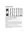
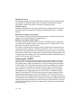
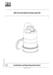
MULTI US 7002
Battery Charger
For lead-acid batteries 14–150Ah
User Manual and Guide to professional
charging of starter and deep cycle batteries.
Model 1018
US
INTRODUCTION
The MULTI US 7002 is a primary switch mode battery charger with pulse maintenance.
The MULTI US 7002 is designed to offer maximum life for the battery. MULTI US 7002
is a member of a family of professional chargers from CTEK Power Inc. It represents the
state-of-the-art of today’s technology for battery charging. Please read these operating
instructions carefully before operating the MULTI US 7002.
IMPORTANT SAFETY INSTRUCTIONS
California Proposition 65
WARNING: This product contains chemical known to the state of California to cause
cancer or reproductive toxicity.
1. SAVE THESE INSTRUCTIONS – This manual contains
2.
3.
4.
5.
6.
7.
8.
9.
10.
important safety and operating instructions for battery charger models 1018.
When charging, batteries can emit explosive gases, therefore it is essential to preYHQWÀDPHVDQGVSDUNV7KHFKDUJHULVGHVLJQHGIRUFKDUJLQJOHDGDFLGEDWWHULHV
from 14 to 150Ah. Do not use for any other purpose. Do not expose to rain or snow.
Always provide good ventilation when charging.
Use of an attachment not recommended or sold by the battery charger manufacWXUHUPD\UHVXOWLQDULVNRI¿UHHOHFWULFVKRFNRULQMXU\WRSHUVRQV
To reduce risk of damage to electric plug and cord, pull by the plug rather than cord
when disconnecting charger.
An extension cord should not be used unless absolutely necessary. Use of imSURSHUH[WHQVLRQFRUGFRXOGUHVXOWLQDULVNRI¿UHDQGHOHFWULFVKRFN,IDQH[WHQsion cord must be used, make sure that: a) Pins on plug of extension cord are the
same number, size and shape as those of plug on charger; b) Extension cord is
properly wired and in good electrical condition; and c) Wire size is large enough for
DFDPSHUHUDWLQJRIFKDUJHUDVVSHFL¿HGLQ³WHFKQLFDOGDWD´
Do not operate charger with damaged cord or plug – return the charger to the
place where purchased.
Never operate the charger if it has received a sharp blow, been dropped or otherZLVHGDPDJHGLQDQ\ZD\WDNHLWWRDTXDOL¿HGVHUYLFHPDQ
'RQRWGLVDVVHPEOHFKDUJHUWDNHLWWRDTXDOL¿HGVHUYLFHPDQZKHQVHUYLFHRUUHSDLULVUHTXLUHG,QFRUUHFWUHDVVHPEO\PD\UHVXOWLQDULVNRIHOHFWULFDOVKRFNRU¿UH
To reduce risk of electric shock, unplug charger from AC outlet before attempting
any maintenance or cleaning. Turning off controls will not reduce the risk.
2 • US
11. WARNING - RISK OF EXPLOSIVE GASES
a) WORKING IN VICINITY OF A LEAD-ACID
BATTERY IS DANGEROUS. BATTERIES
GENERATE EXPLOSIVE GASES DURING
NORMAL BATTERY OPERATION. FOR THIS
REASON, IT IS OF UTMOST IMPORTANCE
THAT, YOU FOLLOW THE INSTRUCTIONS
EACH TIME YOU USE THE CHARGER.
b) To reduce risk of battery explosion, follow these instructions and those published
by the battery manufacturer and the manufacturer of any equipment you intend
to use in vicinity of battery. Review cautionary marking on these products and
on engine.
12. PERSONAL PRECAUTIONS
a) Consider have some one close enough by to come to your aid when you work near
a lead-acid battery.
b) Have plenty of fresh water and soap nearby in case battery acid contacts skin,
clothing or eyes.
c) Wear complete eye protection and clothing protection. Avoid touching eyes while
working near battery.
d) If battery acid contacts skin or clothing, wash immediately with soap and water.
,IDFLGHQWHUVH\HLPPHGLDWHO\ÀRRGH\HZLWKUXQQLQJFROGZDWHUIRUDWOHDVW
minutes and get medical attention immediately.
e) 1(9(5VPRNHRUDOORZDVSDUNRUÀDPHLQYLFLQLW\RIEDWWHU\RUHQJLQH
f) Be extra cautious to reduce risk of dropping a metal tool onto battery. It might spark
or short-circuit battery or other electrical part that may cause explosion.
g) Remove personal metal items such as rings, bracelets, necklaces, and watches
when working with lead-acid battery. A lead-acid battery can produce a short-circuit current high enough to weld a ring or the like to metal, causing a severe burn.
h) Use charger for charging a LEAD-ACID battery only. It is not intended to supply
power to a low voltage electrical system other than in a starter-motor application.
Do not use battery charger for charging dry-cell batteries that are commonly used
ZLWKKRPHDSSOLDQFHV7KHVHEDWWHULHVPD\EXUVWDQGFDXVHLQMXU\WRSHUVRQVDQG
damage to property.
i) Never charge a frozen battery.
US • 3
13. PREPARING TO CHARGE
a) If necessary to remove battery from vehicle to charge, always remove grounded
WHUPLQDOIURPEDWWHU\¿UVW0DNHVXUHDOODFFHVVRULHVLQWKHYHKLFOHDUHRIIVRDV
not to cause an arc.
b) Be sure area around battery is well ventilated while battery is being charged.
c) Clean battery terminals. Be careful to keep corrosion from coming in contact
with eyes.
d) $GGGLVWLOOHGZDWHULQHDFKFHOOXQWLOEDWWHU\DFLGUHDFKHVOHYHOVSHFL¿HGE\EDWWHU\PDQXIDFWXUHU'RQRWRYHU¿OO)RUDEDWWHU\ZLWKRXWUHPRYDEOHFHOOFDSVVXFK
as valve regulated lead acid batteries, carefully follow manufacturer’s recharging
instruction.
e) 6WXG\DOOEDWWHU\PDQXIDFWXUHU¶VVSHFL¿FSUHFDXWLRQVZKLOHFKDUJLQJDQGUHFRPmended rates of charge.
f) Determine voltage of battery by referring to car owner’s manual and make sure that
WKHRXWSXWYROWDJHVHOHFWRUVZLWFKLVVHWDWFRUUHFWYROWDJH,IFKDUJHUKDVDGMXVWDEOH
charge rate, charge battery initially at lowest rate.
14. CHARGER LOCATION
a) Locate charger as far away from battery as DC cables permit.
b) Never place charger directly above battery being charged; gases from battery will
corrode and damage charger.
c) 1HYHUDOORZEDWWHU\DFLGWRGULSRQFKDUJHUZKHQUHDGLQJHOHFWURO\WHVSHFL¿FJUDYLW\
RU¿OOLQJEDWWHU\
d) Do not operate charger in a closed-in area or restrict ventilation in any way.
e) Do not set a battery on top of charger.
15. DC CONNECTION PRECAUTIONS
a) Connect and disconnect dc output clips only after setting any charger switches to
³RII´SRVLWLRQDQGUHPRYLQJDFFRUGIURPHOHFWULFRXWOHW1HYHUDOORZFOLSVWRWRXFK
each other.
b) Attach clips to battery and chassis as indicated in 16(e), 16(f), 17(b) through 17(d).
16. FOLLOW THESE STEPS WHEN BATTERY
IS INSTALLED IN VEHICLE. A SPARK
NEAR BATTERY MAY CAUSE BATTERY
EXPLOSION. TO REDUCE RISK OF A SPARK
NEAR BATTERY:
4 • US
a) Position AC and DC cords to reduce risk of damage by hood, door or moving
engine part.
b) 6WD\FOHDURIIDQEODGHVEHOWVSXOOH\VDQGRWKHUSDUWVWKDWFDQFDXVHLQMXU\WR
persons.
c) Check polarity of battery posts. POSITIVE (POS, P, +) battery post usually has
larger diameter than NEGATIVE (NEG, N, -) post.
d) Determine which post of battery is grounded (connected) to the chassis. If negative post is grounded to the chassis (as in most vehicles) see (e). If positive post is
grounded to the chassis, see (f).
e) For Negative-grounded vehicle, connect POSITIVE (RED) clip from battery
charger to POSITIVE (POS, P, +) ungrounded post of battery. Connect NEGATIVE
(BLACK) clip to vehicle chassis or engine block away from battery. Do not connect
clip to carburetor, fuel lines, or sheet-metal body parts. Connect to a heavy gage
metal part of the frame or engine block.
Charger connection.
1. Connect positive charger clip (red) to positive battery terminal.
2. Connect negative charger clip (black) to a good metal engine ground away from
the battery. Do no connect clip to fuel lines or sheet-metal body parts.
3. Connect the AC cord to the socket. The red alarm indication light will indicate
a battery which is connected to reverse polarity.
f) For Positive grounded vehicle, connect NEGATIVE (BLACK) clip from battery
charger to NEGATIVE (NEG, N, –) ungrounded post of battery. Connect POSITIVE
(RED) clip to vehicle chassis or engine block away from battery. Do not connect
clip to carburetor, fuel lines, or sheet-metal body parts. Connect to a heavy gage
metal part of the frame or engine block.
Charger connection.
1. Connect negative charger clip (black) to negative battery terminal.
2. Connect positive charger clip (red) to a good metal engine ground away from the
battery. Do no connect clip to fuel lines or sheet-metal body parts.
3. Connect the AC cord to the socket. The red alarm indication light will indicate
a battery which is connected to reverse polarity.
g) When disconnecting charger, turn switches to off, disconnect AC cord, remove clip
from vehicle chassis, and then remove clip from battery terminal.
h) See operating instructions for length of charge information.
US • 5
17. FOLLOW THESE STEPS WHEN BATTERY
IS OUTSIDE VEHICLE. A SPARK NEAR
BATTERY MAY CAUSE BATTERY
EXPLOSION. TO REDUCE RISK OF
A SPARK NEAR BATTERY:
a) Check polarity of battery terminals. POSITIVE (POS, P, +) battery post usually has
a larger diameter than NEGATIVE (NEG, N, -) post.
b) Attach at least a 24-inch-long 6-gauge (AWG) insulated battery cable to
NEGATIVE (NEG, N, -) battery post.
c) Connect POSITIVE (RED) charger clip to POSITIVE (POS, P, +) battery of post.
d) Position yourself and free end of cable as far away from battery as possible – then
connect NEGATIVE (BLACK) charger clip to free end of cable.
e) 'RQRWIDFHWKHEDWWHU\ZKHQPDNLQJWKH¿QDOFRQQHFWLRQ
f) When disconnecting charger, always do so in reverse sequence of connecting
SURFHGXUHDQGEUHDN¿UVWFRQQHFWLRQZKLOHDVIDUDZD\IURPEDWWHU\DVSUDFWLFDO
g) When disconnecting charger, disconnect in reverse sequence from connecting
procedure. See operating instructions for charge information.
h) A marine (boat) battery must be removed and charged on shore. To charge it on
board requires equipment specially designed for marine use.
The battery charger must be connected to the battery according to
the instructions above.
IMPORTANT SAFETY INFORMATION!
The MULTI US 7002 cannot be used to restore a fully worn out battery.
If the MULTI US 7002 does not switch to maintenance charge after three days (green light
illuminated), there is a fault. Possible causes:
• The battery is probably worn out and should be replaced.
• Some large antimony batteries may behave different and can allow the MULTI US 7002
to charge the battery for too long, which can lead to overcharging. See caution!
• ,IKHDY\SRZHUFRQVXPHUVOLNH¿WWHGDODUPVDQGQDYLJDWLRQFRPSXWHUVDUHFRQQHFWHGWR
the battery, the charging process takes longer and this can also overcharge the battery.
• $VXOSKDWHGEDWWHU\ZLOORQO\DFFHSWFXUUHQWZLWKGLI¿FXOW\DQGFRQVHTXHQWO\WKHFKDUJing process takes a particularly long time. A worn out battery cannot be fully charged.
Therefore you should always check whether the charger has been switched to maintenance charge before you leave it turned on or unobserved for any length of time.
6 • US
Caution: If the MULTI US 7002 does not switch to maintenance charge mode after three
days, manually switch it to pulse maintenance mode.
Note: A battery that hasn’t changed to maintenance charge after three days is most likely
worn out and needs to be replaced. All other batteries can be maintained for a very long
time.
BATTERY TYPES AND SETTINGS
MULTI US 7002 can easily be set for different types of batteries or conditions. The following recommendations should, however, only be seen as guidelines. Please consult the
battery manufacturer for further instructions.
6HWWLQJVDUHPDGHE\SUHVVLQJWKH´02'(EXWWRQ´DQGVWHSSLQJIRUZDUGRQHSUHVVDWD
time until the required mode is reached, the button is then released. After about 2 seconds
the charger activates the selected mode. The selected mode is saved in a memory in the
charger and remains there even if the charger is switched off.
Mode 14.4V - Normal setting for wet batteries, maintenance free and for
NORMAL most Gel batteries. Some Gel batteries prefer a slightly lower charging voltage. Please consult the battery manufacturer when in doubt.
Mode 14.7V - This setting is recommended for a battery at temperatures
< 41°F. It is also recommended for many AGM batteries like Optima, and
Odysseys. Consult your battery manufacturer when in doubt.
Mode 13.6V / Supply - The charger is operating at a constant voltage of
SUPPLY 13.6V. This is the maintenance mode for applications where maximum caSDFLW\IURPWKHEDWWHU\LVLPSRUWDQWOLNHÀRRUVZHHSHUVDQGJROIFDUWV1RWH
that the Spark protection function is suppressed in this mode.
Mode 15.7V / 1.5A / 0.5–4h - This mode is used to recover deep discharged
ÀRRGHGEDWWHULHVZKHUH\RXFRXOGH[SHFWDVWUDWL¿HGDFLGKLJKDFLGZHLJKW
in the bottom, low on top). This mode will also recover some spiral cell AGM
batteries that has been deep cycled. Check with battery manufacturer when
in doubt.
RECOND 1RWHWKDWWKHEDWWHU\KDVWREHIXOO\FKDUJHG¿UVW8VHWKLVPRGHZLWKFDUH
because the high voltage will cause some water loss. 16V is normally no
problem for electronics, but consult your supplier when in doubt. Life of light
bulbs will be reduced at higher voltage. Try to avoid using 12V light from the
battery during this phase. Maximum effect and minimum risk for electronics
is achieved by charging a disconnected battery.
US • 7
CHARGING
The battery charger must be connected to the battery according to
the instructions above.
Start charging
1. Connect the power cord to the power outlet.
2. Set the proper charging mode for the battery by pushing the Mode button until the
FRUUHFWVHWWLQJLVOLW&KRRVLQJVHWWLQJVIRU\RXUEDWWHU\LVGHVFULEHGXQGHU´%$77(5<
7<3(6$1'6(77,1*6´
3. The lamp for Deep Discharged battery (1) will indicate if the battery voltage is low.
If lamp 1 blinks, this indicates that the battery is lightly sulphated. Read more under
´&+$5*,1*3+$6(6´
4. Normal charging is indicated by the following lamps: Deep Discharged (1), Bulk Charge
(2), Absorption Charge (3) or Maintenance Charging (4). When the maintenance lamp
is lit, the battery is fully charged. The charge will restart if the voltage drops. The
charger can be connected for months.
SUPPLY or RECOND are indicated when the lamps for these settings are lit (5 or 6).
5. If the battery cables are connected incorrectly, the reverse polarity protection will
make sure that neither the charger nor the battery are damaged. In this case, the red
warning lamp (0) will be lit.
6. If nothing happens. If the setting lamp is lit but no other light comes on, the connection
to the battery or to the chassis may be poor, or the battery may be faulty. Start by
improving the contact between the battery and the charger.
7. Charging can be interrupted at any time by disconnecting the power cord from the wall
socket or by putting the charger in "Standby" mode (lamp A). Always disconnect the
power cord from the socket before removing the battery cables. When you interrupt
charging of a battery mounted in a vehicle, always disconnect the battery cable from
the chassis before removing the other battery cable.
8 • US
Current
CHARGING PHASES
Soft Start
Bulk
Absorption
Analysis
Recond
Float
Pulse
Voltage
Desulphation
Mode chosen: ”NORMAL” or ”SNOWFLAKE”
MULTI US 7002 is a multi stage fully automatic charger. Lamp B for chosen setting
´1250$/´DQGODPS&IRUFKRVHQVHWWLQJ´612:)/$.(´
Desulphation (Lamp 1, blinking)
Desulphation with pulsing for sulphated batteries. Indicated by blinking lamp 1.
Start (Lamp 1)
Starting phase for charging. The starting phase continues until the battery’s terminal voltage has risen over a preset level. At this point, charging goes into the bulk phase. If the
terminal voltage has not reached the preset level within 8 hours, charging is suspended.
The error mode is indicated. This indicates a battery which is faulty or has too large
capacity. If a large battery is charged that has been severely discharged, it may be necessary to restart the charger after 8 hours. Start is indicated by lamp 1.
Bulk (Lamp 2)
Primary charging where approximately 80% of the charging happens. The charger
delivers maximum voltage until the terminal voltage has risen to the preset level. After a
number of hours, the charger goes on to the next phase, even if maximum voltage is not
reached. Bulk is indicated by lamp 2.
US • 9
Absorption (Lamp 3)
Final charging, voltage is kept at the preset level. During this phase, the voltage is gradually reduced. If the maximum length of time for Absorption is exceeded, the charger
automatically continues with Analysis. Absorption is indicated by lamp 3.
Analysis (Lamp 3)
Charging is suspended for a short period and the battery voltage measured. If it falls too
quickly, the battery is probably faulty. Charging is suspended and an error is indicated
(lamp 0).
0DLQWHQDQFHFKDUJLQJÁRDW/DPS
'XULQJWKH¿UVWGD\VRIPDLQWHQDQFHFKDUJLQJWKHEDWWHU\LVPDLQWDLQHGZLWKFRQVWDQW
voltage, 13.6V. Float-maintenance is indicated by lamp 4.
Maintenance charging - pulse (Lamp 4)
The state of charge varies between 95% and 100%. The battery receives a pulse when
the voltage sinks, keeping the battery in good shape when it is not being used. The charger can be connected for months at a time.
If the battery is charged and/or the battery’s terminal voltage drops, the charger starts a
charge pulse until the voltage has reached the preset level, 14.4V or 14.7V. The charge
pulse is then interrupted and the cycle is repeated as long as the charger is in pulse maintenance phase. If the terminal voltage drops even lower, the charger automatically reverts
to the beginning of the charging curve. Pulse maintenance phase is indicated by lamp 4. If
possible, check the water level in the battery.
Chosen mode: ”SUPPLY”
MULTI US 7002 has a Supply mode setting which has a constant voltage of 13.6V and
current up to 7A. This mode can also be used for maintenance charging of an already
fully charged battery, called Float maintenance. This type of charging keeps the battery
at 100% charge. The constant small overcharge can also increase water loss. A battery
does not have to be connected for the charger to deliver voltage. This means that the
spark protection is not active in this mode. It is not appropriate to charge a completely
discharged battery in Supply mode, since this will not result in a completely charged
battery. In this mode, MULTI US 7002 can also be used as a power generation unit for
operating equipment that requires 13.6V and a maximum of 7A. If the selected current
exceeds 7A, the output voltage will drop as the load increases. The charger has electronic
overload protection in this mode, which is activated if the charge is so great that the output
voltage from the charger falls below around 9V and the current ís around 7A. In the event
of an overload, the charger goes into error mode (lamp 0). Supply mode is indicated with
lamp D and lamp 5.
10 • US
Chosen mode: ”RECOND”
MULTI US 7002 has a Recond mode which is used to recondition a battery that has been
VHYHUHO\GLVFKDUJHG7KHEDWWHU\LV¿UVWFKDUJHGXVLQJWKHPRGH´1250$/´:KHQWKH
analysis phase is complete, the charger begins reconditioning the battery by providing a
constant current of 1.5A and a maximum voltage of 15.7V. After 0.5–4 hours, the battery
is completely reconditioned and the charger goes into pulse maintenance. The battery is
ready to be used, or store it with pulse maintenance active until you are ready to use the
battery. Recond is indicated by lamp E and lamp 6. Note that the recond phase begins
with normal charging and that the charger therefore will indicate the charging phases acFRUGLQJWRWKHGHVFULSWLRQVDERYH¿UVW/DPSLV¿UVWOLWZKHQWKHUHFRQGLWLRQLQJEHJLQs.
INDICATORS
3
2
1
0
4
5
SUPPLY
6
RECOND
MODE
A
B
NORMAL
C
D
E
SUPPLY RECOND
Indication Description
0
1
2
3
4
5
6
Error mode, the charger suspends the charging / voltage maintenance.
See further description below.
Start mode.
Bulk charging, maximum voltage.
Absorption charging, voltage limited to chosen voltage.
Pulse maintenance charging
6XSSO\PRGH¿[HGRXWSXWYROWDJHQRFRXQWHUYROWDJHUHTXLUHPHQW
Recond charging
A
B
C
D
E
STANDBY
0RGH´1250$/´9
0RGH´612:)/$.(´9
0RGH´6833/<´9
0RGH´5(&21'´9$±K
US • 11
Error mode
The charger enters error mode before start in the following situations:
• The battery is connected with poles reversed to the charger's terminals.
• The terminals on the charger are short-circuited.
Error mode before start is reset by removing the error situation. The charger restarts in
the latest selected mode.
The charger enters steady error mode in the following situations:
• The charger’s analysis function has interrupted charging.
• The charger is overloaded in Supply mode.
• The charger has been in start mode longer than maximum time.
6WHDG\HUURUPRGHLVDFNQRZOHGJHGUHVHWE\SUHVVLQJWKH´02'(´EXWWRQ7KHFKDUJHU
restarts in the latest selected mode.
BULK CHARGING TIME
12 • US
Battery size (Ah)
Time to ~80% charge (h)
14
50
90
150
2
6–7
11–13
20–22
TECHNICAL DATA
Model
Voltage AC
1018
100–115VAC, 50–60Hz. Output power is reduced at
lower input voltage.
Current
2.0A rms
Back Current Drain*
< 3mA
Charging Voltage
Nominal: 12V or 15.7V
Ripple**
Max 150mV rms, max 0.3A
Charging Current
7A max
Battery cable fuse
15A
Ambient Temperature
-4°F to +122°F. Automatic reduction of power at increased
ambient temperature.
Cooling
Natural convection. Do not cover the charger.
Charge cycle
MULTI US 7002 is a multistage fully automatic charger.
Type of batteries
All types of lead-acid batteries (Wet, Maintenance Free, AGM
and most GEL).
Battery Capacity
14–150Ah
Dimensions
81/2 x 31/2 x 17/8 inches (L x W x H)
Insulation
Raintight.
Weight
1.7 lbs
*) Back Current Drain is what the charger uses to drain the battery if the power cord is
disconnected. The reverse current of the MULTI US 7002 is very low and corresponds to
1Ah per month.
**) The ripple wave describes how many disturbances are exhibited by current and voltage. A rippled voltage can cause damage to other equipment connected to the battery.
The MULTI US 7002 supplies voltage and current with very low voltage rippling. This
increases the life of the battery and ensures that equipment connected to it will not be
damaged.
Recommended Minimum AWG Size for AC Extension cords
Length of cord feet (m)
AWG Size of cord
25 (7.6)
50 (15.2)
100 (30.5)
150 (45.6)
18
18
18
16
US • 13
OVERHEATING PROTECTION
The MULTI US 7002 is equipped with overheating protection. In high ambient temperatures the output power is reduced. Do not cover the charger.
BATTERY CABLES
MULTI US 7002 is equipped with a set of battery cables with battery terminal clips and
one set of battery cables with eyelet terminals. Do not shorten the battery cables.
Connecting the provided cables with eyelet terminals
Make sure that the cable is not pinched or in contact with warm surfaces or sharp edges.
When the cable is mounted on the battery, it should not be connected to the charger.
Connect the eyelet terminals to the battery's poles - the red cable to the positive pole and
the black cable to the negative pole. After this, the quick connector can be connected.
MAINTENANCE
The MULTI US 7002 is maintenance-free. The charger must not be opened; doing so will
invalidate the warranty. If the power cable is damaged it must be replaced by CTEK or its
authorized representative. The charger casing can be cleaned using a damp cloth and
mild cleaning agent. Remove the plug from the power socket before cleaning.
LIMITED WARRANTY
CTEK Power Inc, 2374 Edison Blvd, Twinsburg, OH 44087-2376, USA issues this limited
warranty to the original purchaser of this product. This limited warranty is not transferable.
CTEK Power Inc warrants this unit for 5 years from the date of purchase against defect
workmanship or material. It is the obligation of the purchaser to forward the unit together
with proof of purchase to the manufacturer or its representative with transportation cost
prepaid. This warranty is void if the unit is abused, handled carelessly or repaired by anyone other than CTEK Power Inc or its authorized representative. CTEK Power Inc makes
no warranty other than this limited warranty and expressly excludes any implied warranty
including any warranty for consequential damages. This is the only expressed limited
warranty and CTEK Power Inc neither assumes nor authorizes anyone to assume or make
any other obligation towards the product other than this limited warranty.
CTEK Power Inc.
2374 Edison Blvd
Twinsburg, OH 44087-2376
USA
Fax: + 1 330 963 0982
www.ctek.com
14 • US