1
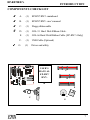
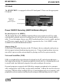
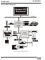
EP-BX7/BX7+
A Socket 370 Processor based Mainbord
TRADEMARKS
All products and company names are trademarks or registered
trademarks of their respectives holders.
These specifications are subject to change without notice.
Manual Revision1.2
May.26 2000
PREFACE
EP-BX7/BX7+
This User’s Manual specifies the board layout, components, connectors, power and
environmental requirements, and the BIOS for the EP-BX7/BX7+ mainboard. It
describes the standard mainboard product and available manufacturing options. The
manual is intended to provide detailed, technical information about the mainboard and
its components to the vendors, system integrators, other engineers and technicians,
and the general audience who need this information.
What This Document Contains
Chapter
1
2
3
4
5
Description
Introduction
Overview
Hardware Installation
Award Bios Setup
Appendix A-E
Safety Instructions
1.
2.
3.
4.
5.
Always read the safety instructions carefully.
Keep this User’s manual for furture reference.
Keep this equipment away from humidity.
Lay this equipment on a reliable flat surface before setting it up.
The openings on the enclosure are for air convection hence protects the equipment
from overheating. DO NOT COVER THE OPENINGS.
6. Make sure the voltage of the power source and adjust properly 110/220V before
connecting the equipment to the power inlet.
7. Place the power cord such a way that people can not step on it. Do not place
anything over the power cord.
8. Always Unplug the Power Cord before inserting any add-on card or module.
9. All cautions and warnings on the equipment should be noted.
10. Never pour any liquid into the opening that could damage or cause electrical
shock.
11. If any of the following situations arises, get the equipment checked by a service
personnel:
• The power cord or plug is damaged
• Liquid has penetrated into the equipment
• The equipment has been exposed to moisture
• The equipment has not work well or you can not get it working according to
User’s Manual.
• The equipment has dropped and damaged
• If the equipment has obvious sign of breakage
2
EP-BX7/BX7+
TABLE OF CONTENTS
Table of Contents
Chapter 1: Introduction
Component Checklist .......................................................................... 7
User Notice ......................................................................................... 8
Handling Procedure ............................................................................ 8
Technical Support Service .................................................................. 9
Contact Technical Support .................................................................. 9
Chapter 2: Overview
Features ............................................................................................ 11
Intel Celeron Processors (P.P.G.A.)370 .......................................... 14
Intel Coppermine Procssors (FC-PGA) 370 .................................... 15
Accelerated Graphics Port (AGP) .................................................... 16
ATX Form Factor .............................................................................. 17
Hardware Monitoring ....................................................................... 18
Input/Output Shield ........................................................................... 19
Power ON/OFF Remotely (KBPO & Modem Ring-in) .................. 19
Universal Serial Bus .......................................................................... 19
System Block Diagram ...................................................................... 20
Chapter 3: Hardware Installation
Detailed Board Layout ..................................................................... 22
Directions & Recommended Tools ................................................... 23
Configuration of Jumper ................................................................... 24
Installing into ATX case .................................................................... 25
Installing Connectors ........................................................................ 26
Installing Memory ............................................................................. 27
Installing Processor(s) ...................................................................... 29
Device Connector Description .......................................................... 31
External Modem Ring-in Power on and KBPO Function ............... 33
3
TABLE OF CONTENTS
EP-BX7/BX7+
Chapter 4: Award BIOS Setup
BIOS Instructions ................................................................................ 36
Standard CMOS Setup. ........................................................................ 37
BIOS Features Setup ............................................................................ 38
Chipset Features Setup ............................................................................... 42
Power Management Setup ................................................................................45
PNP/PCI Configuration .......................................................................................49
Load Setup Defaults .............................................................................................. 51
Integrated Peripherals ........................................................................................ 51
Sensor and CPU Speed Setting ....................................................................... 56
Change Supervisor or User Passwor ................................................................ 58
IDE HDD Auto Detection .................................................................................. 59
Save & Exit Setup .............................................................................................. .. 61
Exit Without Saving ............................................................................................. 61
Chapter 5: Appendix
Appendix A: Technical Information
Memory Map .................................................................................. A-1
I/O Map ........................................................................................... A-1
Timer & DMA Channel Map ........................................................... A-2
Interrupt Map .................................................................................. A-2
RTC & CMOS RAM Map ............................................................. A-3
Appendix B: BIOS Post Codes
Post Codes ....................................................................................... B-1
Unexpected Errors .......................................................................... B-4
Appendix C: Load Setup Defaults
......................................................................................................... C-1
Appendix D: BIOS Beep Codes
....................................................................................................
4
D-1
EP-BX7/BX7+
TABLE OF CONTENTS
Appendix E: Frequently Asked Questions
Tips to install motherboards .......................................................... E-1
BIOS flash instructions .................................................................... E-2
BIOS function S.M.A.R.T. ............................................................. E-5
BIOS recovery if flash fails ............................................................. E-5
KBPO does not work ...................................................................... E-5
Memory conflict with AGP in Windows® 95 ................................. E-6
“MSDOS Compatibility mode” in Windows® 95/98 ......................... E-6
New hard drive cannot be accessed ................................................ E-7
No video when power applied .......................................................... E-8
“PCI Bridge” and Device Manager of Windows® 95/98 ................. E-9
“PCI Serial Controller” and Device Manager of Windows® 95/98
........................................................................................................ E-9
WOL connector ........................................................................... E-10
Ghost 5.1 Quick User’s Guide ...................................................... E-11
5
EP-BX7/BX7+
CHAPTER 1
INTR
ODUCTION
INTRODUCTION
SUBJECTS COVERED:
a) Components Checklist
b) User Notice
c) Handling Procedure
d) Technical Support Services
e) Contacting Technical Support
6
EP-BX7/BX7+
INTRODUCTION
COMPONENTS CHECKLIST
A.
(1)
EP-BX7/BX7+ mainboard
B.
(1)
EP-BX7/BX7+ user’s manual
C.
(1)
Floppy ribbon cable
D.
(1)
ATA-33 Hard Disk Ribbon Cable.
E.
(1)
ATA-66 Hard Disk Ribbon Cable. (EP-BX7+ Only)
F.
(1)
USB Cable (Optional)
G.
(1)
Driver and utility
USER’S
MANUAL
C
EP-BX7/
BX7+
D
B
A
E
F
or
G
7
EP-BX7/BX7+
INTRODCUTION
USER NOTICE
This manual, including the products and softwares described in it, may not be
reproduced, transmitted, transcribed, stored in a retrieval system, or translated into any
language in any form or by any means, without the express written permission of
EPoX Computer CO., INC. (hereinafter referred to as EPoX), except for documentation kept by the purchaser for backup purposes.
EPoX provides this manual “AS IS” without warranty of any kind, either express or
implied, including but not limited to the implied warranties or conditions of merchantability or fitness for a particular purpose. In no event shall EPoX be liable for anyloss
of business or for indirect, special incidental, or censequesntial damages of any kind,
even if EPoX has been advised of the possibility of such damage arising from any
defect or error in the manual or product. EPoX may review this manual from time to
time without notice.
The EP-BX7/BX7+ and revision number are both printed on the mainboard itself. For
updated BIOS, drivers, or product release information, you may visit EPoX’s home
page at : http://www.epox.com or http://www.epox.com.tw
Products mentioned in this manual are mentioned for identification purposes only.
EP-BX7/BX7+ appearing in this manual may or may not be registered trademarks or
copyrights of their respective companies.
Handling Procedures
Static electricity can severely damage your epquipment. Handle the EP-BX7/BX7+
and any other device in your system with extreme care and avoide unnecessary
contact with system components on the mainboard. Always work on an antistatic
surface to avoid possible damage to the mainboard from static discharge. Always
have the power supply unplugged and powered off when inserting and removing
devices within the computer chassis. EPoX assume no reponsibility for any damage to
the EP-BX7/BX7+ mainboard that results from failure to follow instructions or
CAUTION
The EP-BX7/BX7+mainboard is subject to damage
by static electricity. Always observe the handling
8
EP-BX7/BX7+
INTRODUCTION
Technical Support Services
If you need additional information, help during installation or normal use of this
product, please contact your retailer. Your retailer will have the most current information about your configuration. If your retailer cannot help, you may visit our online
technical support website and/or contact our support technicians at the locations listed
below.
Record your serial number before installing your EP-BX7/BX7+ mainboard. (The
serial number is located near the ISA slots at the edge of the board.)
EP-BX7/BX7+ serial number: _________________________________
Contacting Technical Support
EPoX technical support is working hard to answer all of your questions online. From
our website you can find answers to many common questions, drivers, BIOS updates,
tech notes, and important technical bulletins. If you are still unable to locate the
solution you are seeking, you always have the option to contact our support technicians
directly.
North American website (English language)
http://www.epox.com
[email protected]
[email protected]
European website (Multi-language)
http://www.epox.nl
[email protected]
[email protected]
info @elito-epox.com
Taiwan website (Chinese language)
http://www.epox.com.tw
[email protected]
[email protected]
Thank you for using EPoX mainboards!
Copyright 2000 EPoX Computer Company. All rights reserved.
9
OVERVIEW
EP-BX7/BX7+
CHAPTER 2
OVER
VIEW
VERVIEW
SUBJECTS COVERED:
a) Features
b)Intel Celeron processors (P.P.G.A.) 370
c)Intel Coppermine processors (FC-PGA) 370
d) Accelerated Graphics Port (AGP)
e) ATX Form Factor
f) Hardware Monitoring
g) Input/Output Shield
h) Power ON/OFF Remotely (KBPO & Modem
Ring-in)
i) Universal Serial Bus (USB)
10
EP-BX7/BX7+
OVERVIEW
The EP-BX7/BX7+ mainboard’s features are summarized below.
Form Factor
ATX
Processor
370 Processor including PPGA & FC-PGA
Operating at 300-800MHz
Chipset
Intel 82443BX AGPset
Memory
168-pin DIMM x 4
Supports up 1 GB of SDRAM(minimum of 8MB)
on board
EP-BX7/BX7+ will support Error Checking and
Correcting (ECC) when using paritys DRAM
memory modules
Automatically detect at 66 MHz Synchronous
DRAM memory (SDRAM) at 66MHz or 100MHz
I/O Control
Provides independent high performance PCI IDE
interface capable of supporting PIO Mode 3/14
and Ultra DMA 33 devices.
Only the BX7/BX7+ supports Ultra DMA 66
devices
Support ATAPI devices on both Primary and
Secondary IDE interface
Designed with Winbond W 83977TF/EF Multi I/O
Peripheral
Interfaces
1 floppy port
1 parallel port
2 serial ports
Note :Japanese “Floppy3 mode” is also
supported.
11
OVERVIEW
EP-BX7/BX7+
1 PS/2 mouse connector
1 PS/2 keyboard
5 USB Port Max.(2 ports on boards, 3 ports for
option)
Video
No Video On Board
Expansion
1*16 bit ISA
Capabilities
6*32 bit PCI Slot (All Master)
1*AGP
Supports PCI Bus Master slots and a jumpless PCI
INT# control scheme which reduces configuration
confusion when plugging in PCI card(s).
BIOS
Capabilities Software power-down when using
Windows® 95/98 or Windows® 2000.
Support ring-in feature(Remote Power-on through
external modem,allow system to be turned
remotely) .
Resume by Alarm:Allow system to turn on at a
preselected time.
Power Loss Recovery:In the event of power
outage your system will automatically turn itself
back on without user intervention.
Support CPU Hardware sleep and SIMM (System
Management Mode)
Supports Desktop Management Interface (DMI)
facilitating the management of desktop computers,
hardware and software components and
peripherals, whether they are stand-alone systems
or linked into networks. (Optional)
12
EP-BX7/BX7+
OVERVIEW
Supports Hot key, any key or password Keyboard
Power On function (KBPO)
Support USDM software to allow the status
monitoring of various aspects of the system when
using Windows 98/95 or Windows NT 4.0
Support the CPU, PWR and Chassis fan Auto stop
in the sleep mode.
Supports the System Power LED (PANEL) blinks
in the sleep mode
Build-in WOL (Wake On Lan) Connector
Power Source
EP-BX7/BX7+ utilizes a Lithium battery which
provides environmental protection and longer batter
life
Built-in ATX 20-pin power supply connector
13
OVERVIEW
EP-BX7/BX7+
Intel Celeron processors (P.P.G.A)370
The Intel Celeron processors provide power to handle the internet, educational
programs, interactive 3D games, and productivity applications. The Intel Celeron processors at 533, 500, 466, 433, 400, 366, 333 and 300A MHz include integrated L2
cache 128Kbyte. The core for the 533, 500, 466, 433, 400, 366, 333 and 300A
MHz processors have 19M transistors due to the addition of the integrated L2 cache
128Kbyte. All the Intel Celeron processors are available in the plastic pin grid array
(P.P.G.A.) form factor. The P.P.G.A. form factor is compatible with the 370 pin
socket. All the Intel Celeron processors are available in the plastic pin grid array (PPGA)
package. The PPGA package is compatible with the 370 pin socket and provides
more flexibility to design low cost systems by enabling lower profile and smaller systems and providing the potential for reducing costs of processor retention and cooling
solutions. Like the Intel Celeron processors that utilize S.E.P.P., the Intel Celeron
processors that use P.P.G.A., feature a P6-microarchitecture-based core processor
on a single-sided substrate without BSRAM componentry.
The Intel Celeron processor at 533, 500, 466, 433, 400, 366, 333, and 300A
MHz. Includes Intel MMX[tm] media enhancement technology. Offers Dynamic Execution technology.
Includes a 32Kbyte (16Kbyte/16Kbyte) non-blocking, level-one cache that provides fast access to heavily used data. Intel Celeron processors at 533, 500, 466,
433, 400, 366, 333 and 300A MHz include integrated L2 cache 128Kbyte. All the
Intel Celeron processor utilize the Intel P6 microarchitecture’s multi-transaction system bus at 66MHz. The 533, 500, 466, 433, 400, 366, 333 and 300A MHz processors utilize the Intel P6 microarchitecture’s multi-transaction system bus with the addition of the L2 cache interface. The combination of the L2 cache bus and the processor-to-main-memory system bus increases bandwidth and performance over singlebus processors.Intel MMX technology includes new instructions and data types that
allow applications to achieve a new level of performance. Intel’s MMX technology is
designed as a set of basic, general-purpose integer instructions that are easily applied
to the needs of a wide diversity of multimedia and communications applications. The
highlights of the technology are: * Single Instruction, Multiple Data (SIMD) technique
* 57 new instructions
* Eight 64-bit wide MMX technology registers
* Four new data types
14
EP-BX7/BX7+
OVERVIEW
Intel Coppermine processors (FC-PGA) 370
These Coppermine-128K and Coppermine-256K processor is the next addition to the P6 micro architecture product family. The FC-PGA package is a new
addition to the Intel IA-32 processor line and hereafter will be referred to as the
“Coppermine FC-PGA processor”, or simply “The processor”. The package utilizes
the same 370-pin zero insertion force socket (PGA370) used by the Intel Celeron
processor. Thermal solutions are attached directly to the back of the processor core
package without the use of a thermal plate or heat spreader.
The Coppermine processor, like the Intel Celeron, Intel Pentium II and Pentium
III in the P6 family processor, implement a Dynamic Execution micro architecture --a unique combination of multiple branch prediction, data flow analysis, and speculative
execution. This enable these processors to deliver higher performance than the Intel
Pentium processor, while maintaining binary compatibility with all previous Intel Architecture processors. The processor also executes Intel MMX technology instructions for enhanced media and communication performance just as it’s predecessor the
Intel Pentium III processor. Additionally the Coppermine FC-PGA processor executes streaming SIMD (Single-Instruction Multiple Data) Extensions for enhanced
floating point and 3-D application performance. The concept of processor identification,
via CPUID, is extended in the processor family with the addition of a processor serial
number. The processor utilizes multiple low-power states such as AutoHALT, StopGrant, Sleep and Deep Sleep to conserve power during idle times.
15
OVERVIEW
EP-BX7/BX7+
Accelerated Graphics Port (AGP)
The Accelerated Graphics Port (more commonly known as AGP) interface is a new
platform bus specification that enables high performance graphics capabilities, especially 3D. This interface specification will enable 3D applications, which not only
require sufficient information storage so that the monitor image may be refreshed, but
also enough storage to support texture mapping, z-buffering and alpha blending.
PCI will continue to be the main general-purpose system I/O bus. The AGP interface
has been designed specifically for dedicated use by graphics controllers, and is not
intended to replace PCI. It is physically separated from the PCI bus and it uses a
separate connector.
The benefits of AGP:
1. Direct texturing from main memory:
-Two memory pipes are provided to graphic engines for concurrency.
-Richer textures with no frame buffer growth.
-Graphics & CPU get a continuous view of graphic data structures from “GART”
(Graphics Address Re-mapping Table) Hardware.
2. De-multiplexed address and data.
-Enables pipelining and concurrency.
3. 533 Mbytes /s peak bandwidth. -Delivers high performance data control.
4. Peak bandwidth can be 4 times the PCI bus bandwidth, and higher sustained rates
via Sideband and pipelining.
5. Direct Memory Execute Textures.
6. Reduced Contention with the CPU and I/O devices for bus and memory access.
The PCI bus serves disk controllers, LAN chips, and possibly video capture. AGP
operates concurrently with and independent from most PCI operations.
Furthermore, the CPU can accesses system RAM while with the AGP graphic chip
reads RAM, because of out-of-order queuing hardware support in the chip set.
Therefore, in spite of the heavy access from the graphic chip, there should be no
audio breakup or other CPU degradation.
7. A separate port for the graphics chip to access memory, which allows for concurrent texture reads from AGP memory while read/writing from local memory.
Efficient utilization of the bandwidths allows the graphic chip to obtain 1.3 GB/s
peak by using both ports simultaneously, versus 0.8 GB/s from the local RAM.
8. Allowing the CPU to write directly to AGP shared system memory
16
EP-BX7/BX7+
OVERVIEW
ATX Form Factor
The EPoX EP-BX7/BX7+ is designed with ATX form factor - the latest industry
standard of chassis. The ATX form factor is essentially a Baby-AT baseboard rotated
90 degrees within the chassis enclosure and a new mounting configuration for the
power supply. With these changes the processor is relocated away from the expansion slots, allowing them all to hold full length add-in cards. ATX defines a double
height aperture to the rear of the chassis which can be used to host a wide range of
onboard I/O. Only the size and position of this aperture is defined, allowing PC
manufacturers to add new I/O features (e.g.; TV input, TV output, joystick, modem,
LAN, audio, etc.) to systems. This will help systems integrators differentiate their 5
products in the marketplace, and better meet your needs.
• By integrating more I/O down onto the board and better positioning the hard drive
and floppy connectors material cost of cables and add-in cards is reduced.
• By reducing the number of cables and components in the system, manufacturing
time and inventory holding costs are reduced and reliability will increase.
• By using an optimized power supply, it's possible to reduce cooling costs and lower
acoustical noise.
Single chassis
fan for system
Expandable I/O
Micro
ATX/
AT X
Power
Supply
Full length
slots
Floppy / IDE
connectors
close to
peripheral
bays
CPU located near
Power Supply
MicroATX/ATX
power connector
3 1/2"
Bay
5 1/4"
Bay
17
OVERVIEW
EP-BX7/BX7+
The EP-BX7/BX7+ is equipped with an ATX power supply connectors, which are
20-pin input devices for ATX power supplies. When attached to an ATX supply with
an 20-pin supply connector cables ensures a steady supply of current to the mainboard and devices.
To implement the built-in remote on/off function of the ATX power supply a momentary switch, which is normally open, should be connected to the PW-ON connector on
the motherboard as the on/off switch.
Based on the ATX form factor the EP-BX7/BX7+ has been designed to support
many ACPI and soft-off functions. According to the definition of ACPI: suspend
mode will be enabled while pressing the system on/off button for less than 4 seconds.
Nevertheless the system can always be turned off by pressing the system on/off
button for more than 4 seconds or by using the soft-off function if supported by the
operating system.
Hardware Monitoring
Hardware monitoring allows you to monitor various aspects of your systems operations and status. These include features such as CPU temperature, voltage and fan
RPM’s. By entering the Award BIOS CMOS utility and selecting the Chipset Features section you can monitor this information.
18
EP-BX7/BX7+
OVERVIEW
I/O Shield
The EP-BX7/BX7+ is equipped with an I/O back panel. Please use the appropriate
I/O shield.
Parallel Port
Figure 4:
I/O back
panel layout
PS/2 Mouse
PS/2 Keyboard
USB
COM1
COM2
Power ON/OFF Remotely (KBPO & Modem Ring-in)
Keyboard power on (KBPO)
The Keyboard Power-On (KBPO) function allows users to turn on a PC by easily
touching the keyboard instead of bending down to look for the power button under a
table. To use this unique feature your EPoX motherboard have it set to enable, and use
an ATX power supply rated 0.1a (100mA) or greater for the +5vsb. KBPO is only
available on selected motherboard models.
Modem Ring-IN
On the basis of bounded functions in the I/O chipset, the two onboard serial ports are
able to support external modem ring-in power-on. Using external modems users are
now able to power on the system simply by placing a call to the system remotely.
Universal Serial Bus (USB)
USB is a peripheral bus specification developed by the PC and telecom industries —
that brings plug and play of computer peripherals outside the box, eliminating the need
to install cards into dedicated computer slots and reconfigure the system.
Personal computers equipped with USB allow computer peripherals to be automatically configured as soon as they are physically attached - without the need to reboot or
run setup. USB also allows multiple devices to run simultaneously on a computer, with
peripherals such as monitors and keyboards acting as additional plug-in sites, or hubs.
19
OVERVIEW
EP-BX7/BX7+
System Block Diagram
Socket 370
Processor
100/66MHz
66MHz
100/66MHz
PAC
PCI Bridge
and memory
controller
443BX
PllX4E
I/O Bridge
Figure 5: System Block Diagram
20
EP-BX7/BX7+
HARDWARE INSTALLATION
Cha
pter 3
Chapter
d war
e Installa
tion
Hard
are
Installation
Har
SUBJECTS COVERED:
a) Directions & Recommended Tools
b) Installing into ATX Case
c) Installing Connectors
d) Installing Memory
e) Installing Processor
f) Device Connector Description
g) Configuring KBPO & Modem Ring-in
21
HARDWARE INSTALLATION
EP-BX7/BX7+
EP-BX7/BX7+ Detailed Layout
For EP- BX7+ Only
22
EP-BX7/BX7+
HARDWARE INSTALLATION
Directions & Recommended Tools
Thank you for using EPoX products! This chapter will discuss some general steps
needed in order to get your new mainboard installed and operational. The
EP-BX7/BX7+ is a high performance mainboard which allows the use of Intel
Celeron / Coppermine Socket 370 processors. The mainboard uses the ATX form
factor and requires a matching case. Below you will find our recommended installation procedure for fast and easy setup.
Step 1 - Configuration of Jumpers .................................................... 24
Step 2 - Installing into ATX case ....................................................... 25
Step 3 - Installing Connectors ........................................................... 26
Step 4 - Installing Memory ............................................................... 27
Step 5 - Installing Processor(s) ......................................................... 29
Step 6 -Device Connector Description ............................................. 31
Step7- Configuring KBPO & Modem Ring-in ................................. 33
Recommended Tools (Not Included)
Needle nose pliers: the all purpose needle nose
pliers is useful for many purposes such as, tightening
loose standoffs when no socket is available, holding
screws & jumpers, cutting plastic tie-offs, etc.
Phillips and flat-head screwdrivers: useful for the
actual mouting of the mainboard itself to the case as
well as hard drives, cards, CD-ROM drives, etc.
23
EP-BX7/BX7+
HARDWARE INSTALLATION
Configuration of Jumpers
There are no jumper setting for CPU Speed Setup but detected automatically through the
BIOS.
Default
Auto
Auto
x3
300(100x3)MHz
3:2 (100:66)
3:1 (100:33)
2.10V
3.41V
12.40V
5.50V
5.08V
0.10V
2.10V
JP1
Chassis (Case) intruder dectect
1
JP3
1
JP5
1
LED1
LED2
24
CMOS Clear
JP3 = 1-2 Normal (Default)
= 2-3 Clear CMOS
Keyboard Power-ON Function
JP5 = 1-2 Enabled
= 2-3 Disabled (Default)
Debug card on board
(Please refer to Appendix B for POST
codes)
31oC/87 oF
24oC/75 oF
4900 RPM
4900 RPM
4900 RPM
1.52V
5.02V
11.95V
3.25V
EP-BX7/BX7+
HARDWARE INSTALLATION
Installing into ATX Case
Static electricity can severely damage your equipment. Handle the EP-BX7/BX7+
and any other device in your system with extreme care and avoid unnecessary contact
with system components on the mainboard. Always work on an antistatic surface to
avoid possible damage to the mainboard from static discharge. Always have the
power supply unplugged and powered off when inserting and removing devices within
the computer chassis.
There are countless types, sizes, and shapes when it comes to cases in the computer
industry. Generally the mainboard is mounted into the case using nylon and/or brass
standoffs. These standoffs prevent the mainboard from actually touching the case
itself (shorting) and additionally provides support to prevent bending and warping of
the board during normal use.
1. Observe the safety precautions as listed above.
2. Place the I/O shield into the I/O connector area of the case. An ATX 2.1 compliant
I/O shield should be provided with the system case. The shield ensures proper
cooling and also minimizes EMI.
3. Position the board over the standoffs and slide the motherboard into place noting
that the I/O connectors on the mainboard should protrude slightly through the I/O
shield.
4. Insert matching screws through the mounting holes of the mainboard into the
threaded standoffs. Repeat for all remaining standoffs, and do not over-tighten!
5. Connect any IDE or Floppy drive cables now onto the mainboard. Always observe
the correct orientation of the cables. PIN1 on the cable is signified by a color
stripe. Connect ATX cable(s) from power supply to mainboard (PW1).
6. Install any add-in boards; fully seating them into their respective slots.
7. Move on to the next section to connect case switches and LEDs.
The mainboard is equipped with an ATX power supply connectors (PW1 ) which
when connected to an ATX supply ensuring a ssteady current.
25
HARDWARE INSTALLATION
EP-BX7/BX7+
Installing Connectors
The computer case may supply additional wires which control the function of the
power switch, hard drive LED, power LED and reset among others. This section
outlines where on the mainboard these wires should be attached. PIN1 is designated
as a “1” or “+” unless otherwise noted.
26
1
+ Turbo LED indicator - LED ON when higher speed is selected
IDE LED indicator - LED ON when Onboard PCI IDE Hard disks is
+ activate
Infrared - Infrared connector
1. Vcc
4. GND
2. IRTX
5. IRTX2
3. IRRX2
1
Speaker
KeyLock - Keyboard lock switch & Power LED connector
1. Power LED(+)
4. Keylock
2. N/C
5. GND
1
3. GND
Speaker - Connect to the system's speaker for beeping
1. Speaker
3. GND
1
2. N/C
4. GND
Reset
J2
Pwr LED & Keylock
Infrared
IDE & Turbo
J3
Power On/Off
Power On/Off - This is connected to the power button on the case.
Using the Soft-Off by Pwr-BTTN feature, you can choose either
Instant Off (turns system off immediatly), or 4 sec delay (you need to
hold the button down for 4 seconds before the system turns off).
1 Reset - Closed to restart system.
EP-BX7/BX7+
HARDWARE INSTALLATION
Installing Memory
The EP-BX7/BX7+ supports (4) 168-pin DIMMs (Dual In-line Memory Module). The DIMMs
is for SDRAM (Synchronized DRAM).
•
DIMM SDRAM may be 83MHz (12ns), 100MHz (10ns) or
125MHz (8ns) bus speed.
•
If you use both 50ns and 60ns memory you must configure
your BIOS to read 60ns.
•
When using Synchronous DRAM we recommend using the
4 clock variety over the 2 clock.
Figure below and Table 1 show several possible memory configurations usage
DIMM 1 (M1)
Bank 0/1
DIMM 2 (M2)
DIMM 3 (M3)
Bank 2/3
DIMM 4 (M4)
Bank 6/7
Bank 4/5
-Synchronous
-DRAM
Table 1
Total M e mory
DIM M 1
(Bank 0/1)
DIM M 2
(Bank 2/3)
DIM M 3
(Bank 4/5)
DIM M 4
(Bank 6/7)
= 256MB
Maximum
SDRAM*
8MB, 16MB, 32MB,
64MB, 128MB,
256MB x 1
None
None
None
= 512MB
Maximum
SDRAM*
8MB, 16MB, 32MB,
64MB, 128MB,
256MB x 1
SDRAM*
8MB, 16MB, 32MB,
64MB, 128MB,
256MB x 1
None
None
= 768MB
Maximum
SDRAM*
8MB, 16MB, 32MB,
64MB, 128MB,
256MB x 1
SDRAM*
8MB, 16MB, 32MB,
64MB, 128MB,
256MB x 1
SDRAM*
8MB, 16MB, 32MB,
64MB, 128MB,
256MB x 1
None
= 1GB
Maximum
SDRAM*
8MB, 16MB, 32MB,
64MB, 128MB,
256MB x 1
SDRAM*
8MB, 16MB, 32MB,
64MB, 128MB,
256MB x 1
SDRAM*
8MB, 16MB, 32MB,
64MB, 128MB,
256MB x 1
SDRAM*
8MB, 16MB, 32MB,
64MB, 128MB,
256MB x 1
* SDRAM only supports 8, 16, 32, 64, 128, 256MB DIMM modules.
* We recommend to use PC100 Memory Module for bus speed between 66MHz and
100MHz and PC133 Memory for bus speed over 100MHz.
* Using non-compliant memory with higher bus speed (over clocking) may severely
compromise the integrity of the system.
27
HARDWARE INSTALLATION
EP-BX7/BX7+
DIMM Module Installation & Removal
Figure 1 displays the notch marks and what they should look like on your DIMM
memory module.
DIMMs have 168-pins and two notches that will match with the onboard DIMM
socket. DIMM modules are installed by placing the chip firmly into the socket at a 90
degree angle and pressing straight down (figure 2) until it fits tightly into the DIMM
socket (figure 3).
Figure 1
LEFT KEY ZONE
(UNBUFFERED)
CENTER KEY ZONE
(3.3 V DRAM)
Figure 2
Open DIMM module clip before installing DIMM. When
DIMM is inserted the clip will raise into closed position.
Figure 3
To remove the DIMM module simply press down both
of the white clips on either side and the module will be
released from the socket.
28
EP-BX7/BX7+
HARDWARE INSTALLATION
Installing Processor(s)
CPU Insertion: (use CuMineTM for reference)
Step 1
Open the socket by raising the actuation lever.
Step 2
Insert the processor.
Ensure proper pin 1 orientation by aligning the FCPGA corner marking with the socket corner closest
to the actuation arm tip. The pin field is keyed to
prevent mis-oriented insertion.
Don’t force processor into socket. If it does not go in
easily, check for mis-orientation and debris.
Make sure the processor is fully inserted into the
socket on all sides.
29
HARDWARE INSTALLATION
EP-BX7/BX7+
Step 3
Figure 5
Note:
Close the socket by lowering and locking the actuation lever.
Intel’s reference design thermal solution is an active heatsink; an extruded aluminum
heatsink based and a fan attached to the top on the fin array. (See Figure below)
30
HARDWARE INSTALLATION
EP-BX7/BX7+
Device Connector & Jumper Description
12345678901234567890123456789012123456789012345678901234567890121234567890123456789012345
12345678901234567890123456789012123456789012345678901234567890121234567890123456789012345
PS/2 Mouse
(Top)
PS/2 Keyboard
(Bottom)
USB 1
(Top)
USB 0
(Bottom)
Parallel Port
(Top)
Com1
(Bottom Left)
Figure 4
J1:
Com2
(Bottom
Right)
SB-LINK Connector
• Reserved for Creative SB-LINKTM (Sound Blaster LINKTM) with the Sound Blaster
AWE64D PCI Sound Card to compatible.
J2,J3: Chassis Panel Connector
• Power LED, Speaker, Reset, Turbo LED, HDD LED, IR Conn., Sleep/
Power_ON
J4:
CPU Fan Power
• A plug-in for the CPU Fan Power
J5:
Power Supply Fan Power
• A plug-in for the Power supply Fan Power
J6:
Chassis Fan Power
• A plug-in for the chassis Fan Power
J7:
WOL (Wake On Lan) Connector
• Reserved for NIC (Network Interface Card) to Wake the System.
IDE1:
Primary IDE Connector
IDE2:
Secondary IDE Connector
UIDE1: Ultra ATA66 Primary IDE Connector(EP-BX7+ only)
UIDE2: Ultra ATA66 Secondary IDE Connector(EP-BX7+ only)
31
HARDWARE INSTALLATION
FDD1: Floppy Controller Connector
PW1: ATX Power Connector
• 20-pin power connector
JP4:
USB Connector
• The third ,fourth and fifth USB ports (Cable optional)
USB port header pin descriptions.
PIN#
Wire color
Signal Name
Comment
1
Red
V cc
Cable Power
2
White
-Data
Data
3
Green
+Data
Data
4
Black
Ground
Cable Ground
5
Black
Ground
Case Ground
6
7
NC
Red
Cable Power
8
White
-Data
Data
9
Black
Ground
Cable Ground
10
Black
Ground
Case Ground
11
Green
+Data
Data
12
White
-Data
Data
13
Red
V cc
Cable Power
14
32
V cc
NC
15
Green
+Data
Data
16
Black
Ground
Case Ground
EP-BX7/BX7+
EP-BX7/BX7+
HARDWARE INSTALLATION
External Modem Ring-in Power
ON and Keyboard Power ON
Functions (KBPO)
On the basis of bounded functions in I/O chipset, the two serial ports are able to
support the External Modem Ring-in Power ON function. Once users connect the
external modem to COM1 or COM2, the mainboard allows users to turn on their
system through the remote and host's dial-up control.
Exclusive Keyboard Power ON Function
To innovate a unique feature to benefit users, we devoted the easiest and most
convenient way to turn on your system based on the the ATX power supply.
How to work with it
Step 1: Please check that JP5 is at the position 1-2 after you finished the system
installation.
JP5
1
Keyboard Power-ON Function
JP5 = 1-2 Enabled
= 2-3 Disabled (Default)
Step 2: Push the momentary switch (J3 PW-ON) to turn on your system and then
push again and hold for more than 4 seconds to turn it off affter counting
memory.
Step 3: You can enjoy the Keyboard Power ON function (KBPO) by pressing any 1
key, Hot key (Ctrl-F1, F2.....F12), Password (A maximum of 5 charac ters
can be entered.) and BUTTON only to turn on your system. Please refer to
the BIOS Integrated peripherals setup for detail. The BIOS Default is
keyboard Hot key <Ctrl> - <F1> to turn on the system. Your system will
be turned on automatically, after releasing the keys. To power off you
system, you can use the Soft-OFF function under Windows 95.
33
EP-BX7/BX7+
Notes:
1. Intel ATX version 2.0 specification has recommended you use the
power supply with 0.72A(720mA) in 5.0VSB. With our mainboard, the
5.0VSB standby power only has to be > = 0.1A (100mA) then you
can enjoy this unique benefit. However, the ATX power supply which is <
0.1 (100mA) is still applicable to your system by placed JP4 at the position
2-3 to disable this feature.
2. We recommended you use the power supply with 1.0A in 5.0VSB.
Because this supported PCI 2.1 specification for remote power-on and
wake-up function.
34
EP-BX7/BX7+
Cha
pter 4
Chapter
Awar
d BIOS Setup
ard
SUBJECTS COVERED:
a) BIOS Instructions
b) Standard CMOS Setup
c) BIOS Features Setup
d) Chipset Features Setup
e) Power Management Setup
f) PNP/PCI Configurations Setup
g) Load Setup Defaults
h) Integrated Peripherals
i) Changed Supervisor or User Password
j) IDE HDD Auto Detection
k) Save and Exit Setup
l) Exit without Saving
35
EP-BX7/BX7+
Award BIOS Setup
Section 4
AWARD BIOS SETUP
BIOS Instructions
Award’s ROM BIOS provides a built-in Setup program which allows user to modify the basic
system configuration and hardware parameters. The modified data will be stored in a batterybacked CMOS, so that data will be retained even when the power is turned off. In general, the
information saved in the CMOS RAM will stay unchanged unless there is a configuration
change in the system, such as hard drive replacement or a device is added.
It is possible for the CMOS battery to fail, this will cause data loss in the CMOS only. If this
does happen you will need to reconfigure your BIOS settings.
To enter the Setup Program :
Power on the computer and press the <Del> key immediately, this will bring you into the BIOS
CMOS SETUP UTILITY.
Figure 1: CMOS Setup Utility
36
Award Bios Setup
EP-BX7/BX7+
The menu displays all the major selection items. Select the item you need to reconfigure. The
selection is made by moving the cursor (press any direction key ) to the item and pressing the
‘Enter’ key. An on-line help message is displayed at the bottom of the screen as the cursor is
moved to various items which provides a better understanding of each function. When a
selection is made, the menu of the selected item will appear so that the user can modify
associated configuration parameters.
4-1 Standard CMOS Setup
Choose “Standard CMOS Setup” in the CMOS SETUP UTILITY Menu (Figure 2). The
Standard CMOS Setup allows the user to configure system settings such as the current date
and time, type of hard disk drive installed, floppy drive type, and display type. Memory size is
auto-detected by the BIOS and displayed for your reference. When a field is highlighted (use
direction keys to move the cursor and the <Enter> key to select), the entries in the field can be
changed by pressing the <PgDn> or the <PgUp> key.
Figure 2: Standard CMOS Setup
37
EP-BX7/BX7+
Award BIOS Setup
NOTE: If the hard disk Primary Master/Slave and Secondary Master/Slave are set to
Auto, then the hard disk size and model will be auto-detected.
NOTE: The “Halt On:” field is used to determine when to halt the system by the BIOS if
an error occurs.
NOTE: Floppy 3 Mode support is a mode used to support a special 3.5” drive used in
Japan. This is a 3.5” disk that stores only 1.2 MB, the default setting for this is
disabled.
4-2 BIOS Features Setup
Selecting the “BIOS FEATURES SETUP” option in the CMOS SETUP UTILITY menu allows
users to change system related parameters in the displayed menu. This menu shows all of the
manufacturer’s default values for the EP-BX7/BX7+.
Pressing the [F1] key will display a help message for the selected item.
Figure 3: BIOS Features Setup
Virus Warning: During and after the system boots up, any attempt to write to the boot
sector or partition table of the hard disk drive will halt the system and an error message will
appear.
38
EP-BX7/BX7+
Award BIOS Setup
You should then run an anti-virus program to locate the virus. Keep in mind that this feature
protects only the boot sector, not the entire hard drive.
The default value is Disabled.
Enabled: Activates automatically when the system boots up causing a warning message
to appear when anything attempts to access the boot sector.
Disabled: No warning message will appear when anything attempts to access the boot
sector.
Note:
Many disk diagnostic programs that access the boot sector table can trigger
the virus warning message. If you plan to run such a program, we recommend
that you first disable the virus warning.
CPU Internal Cache: This controls the status of the processor’s internal cache area. The
default is Enabled.
Enabled: This activates the processor’s internal cache thereby increasing performance.
Disabled: This deactivates the processor’s internal cache thereby lowering performance.
External (L2) Cache: This controls the status of the external (L2) cache area.
The default is Enabled.
Enabled: This activates the motherboard’s L2 cache thereby increasing performance.
Disabled: This deactivates the motherboard’s L2 cache thereby lowering performance.
CPU L2 Cache ECC Checking: This controls if the CPU’s L2 cache will support error
Checking and correcting (ECC). The default is Disabled.
Enabled: Enabled ECC support for CPU’s L2 cache. Performance will decrease
2%~4%.
Disabled: Disabled ECC support for CPU’s L2 cache.
Processor Number Feature: Pentium III or later CPU new feature. The default is Enabled.
Enabled: Processor serial number readable.
Disabled: Processor serial number disabled.
39
Award BIOS Setup
EP-BX7/BX7+
Quick Power On Self Test: This category speeds up the Power On Self Test (POST). The
default is Enabled.
Enabled: This setting will shorten or skip of the items checked during POST.
Disabled: Normal POST.
Boot Sequence: This category determines which drive is searched first by the O/S (Operating
System). The default is A,C,SCSI.
The following is your list of options:
[A, C, SCSI] - [C, A, SCSI] - [C, CD-ROM, A] - [CD-ROM, C, A]
[D, A,CD-ROM],[E, A, CD-ROM] - [F, A, CD-ROM] - [SCSI, A, C]
[SCSI C, A] - [C Only]
Boot Up Floppy Seek: During Power-On-Self-Test (POST), BIOS will determine if the floppy
disk drive installed is 40 or 80 tracks. Only 360K type is 40 tracks while 760K, 1.2MB and 1.
44MB are all 80 tracks. The default is Enabled.
Enabled: The BIOS will search the floppy disk drive to determine if it is 40 or 80 tracks.
Disabled: The BIOS will not search for the type of floppy disk drive by track number.
NOTE:
BIOS can not tell the difference between 720K, 1.2MB and 1.44MB drive types
as they are all 80 tracks.
Boot Up NumLock Status: This controls the state of the NumLock key when the system
boots. The default is On.
On:
The keypad acts as a 10-key pad.
Off:
The keypad acts like the cursor keys.
Gate A20 Option: This refers to the way the system addresses memory above 1MB (extended
memory). The default is Fast.
Normal: The A20 signal is controlled by the keyboard controller or chipset hardware.
Fast:
The A20 signal is controlled by Port 92 or chipset specific method.
Typematic Rate Setting: This determines the keystrokes repeat rate.
The default is Disabled.
Enabled: Allows typematic rate and typematic delay programming.
Disabled: The typematic rate and typematic delay will be controlled by the keyboard
controller in your system.
40
EP-BX7/BX7+
Award BIOS Setup
Typematic Rate (Chars/Sec): This is the number of characters that will be repeated by a
keyboard press. The default is 6.
6: 6 characters per second.
8: 8 characters per second.
10: 10 characters per second.
12: 12 characters per second.
15: 15 characters per second.
20: 20 characters per second.
24: 24 characters per second.
30: 30 characters per second.
Typematic Delay (msec): This setting controls the time between the first and the second
character displayed by typematic auto-repeat. The default is 250.
250: 250 msec.
500: 500 msec.
750: 750 msec.
1000: 1000 msec.
Security Option: This category allows you to limit access to the System and Setup, or just to
Setup. The default is Setup.
System: The system will not boot and the access to Setup will be denied if the correct
password is not entered at the prompt.
Setup:
The system will boot; but the access to Setup will be denied if the incorrect
password is not entered at the prompt.
PCI/VGA Palette Snoop: This field controls the ability of a primary PCI VGA controller to
share a common palette (When a snoop write cycles) with an ISA video card. The default is
Disabled.
Enabled: If an ISA card is connected to a PCI VGA card via the VESA connector, and
that ISA card connects to a VGA monitor, then that ISA card uses the
RAMDAC of the PCI card.
Disabled: Disables the VGA card Palette Snoop function.
OS Select For DRAM > 64MB: Some operating systems require special handling. Use this
option only if your system has greater than 64MB of memory.
The default is Non-OS2.
OS2:
Select this if you are running the OS/2 operating system with greater than
64MB of RAM.
Non-OS2:Select this for all other operating systems and configurations.
Report No FDD For WIN95: This option allows BIOS to indicate whether WIN95 is with FDD
or not. The Default value is Yes.
NO:
Report No FDD for WIN95.
YES:
Report FDD for WIN95
41
EP-BX7/BX7+
Award BIOS Setup
4-3 Chipset Features Setup
Choose the “CHIPSET FEATURES SETUP” in the CMOS SETUP UTILITY menu to display
following menu.
Figure 4: Chipset Features Setup
SDRAM RAS-to-CAS Delay: This allows the option to insert a timing delay between the CAS
and RAS strobe signals (used when SDRAM is written to , read from or refreshed). The
default is 3.
2: Provides faster memory performance.
3: Provides slower memory performance.
SDRAM RAS Precharge Time: The precharge time is the number of cycles it takes for the
RAS to accumulate its charge before SDRAM refresh. If insufficient time is allowed, refresh
may be incomplete and the SDRAM may fail to retain data. The default is 3.
2: Provides faster memory performance.
3: Provides better memory compatibility.
SDRAM CAS Latency Time: This setting defines the CAS timing parameter of the SDRAM in
terms of clocks. The default is Auto.
2: Provides faster memory performance.
42
EP-BX7/BX7+
Award BIOS Setup
3: Provides better memory compatibility.
Auto: CAS Latency Time programming depend on information read from DRAM SPD.
SDRAM Precharge Control: The default is Disabled.
Enabled: Enabled the option.
Disabled: Disabled the option.
DRAM Data integrity Mode: Use this option to configure the type of DRAM in your system.
The default is Non-ECC.
Non-ECC: If your memory is Non-ECC, choose this option.
ECC:
If your memory is ECC memory, choose this option.
System BIOS Cacheable: This allows you to copy your BIOS code from slow ROM to fast
RAM. The default is Disabled.
Enabled: The option will improve system performance. However, if any program writes to
this memory area, a system error may result.
Disabled:System BIOS non-cacheable.
Video BIOS Cacheable: This option copies the video ROM BIOS to fast RAM (C0000h to
C7FFFh). The default is Enabled.
Enabled: Enables the Video BIOS Cacheable to speed up the VGA Performance.
Disabled: Will not use the Video BIOS Cacheable function.
Video RAM Cacheable: This option allows the CPU to cache read/writes of the video RAM.
The default is Enabled.
Enabled: This option allows for faster video access.
Disabled: Reduced video performance.
8 Bit I/O Recovery Time: This function allows you to set the wait state that is added to an 8 bit
ISA instruction originated by the PCI bus. The default is 1.
NA: No wait state
8: 8 wait states
1: 1 wait states
2: 2 wait states
3: 3 wait states
4: 4 wait states
5: 5 wait states
6: 6 wait states
7: 7 wait states
43
Award BIOS Setup
EP-BX7/BX7+
16 Bit I/O Recovery Time: This function allows you to set the wait state that is added to an
16 bit ISA instruction originated by the PCI bus. The default is 1.
NA: No wait state
4: 4 wait states
3: 3 wait states
2: 2 wait states
1: 1 wait states
Memory Hole at 15M-16M: You can reserve this memory area for the use of ISA adaptor
ROMs. The default is Disabled.
Enabled: This field enables the main memory (15~16MB) to remap to ISA BUS.
Disabled: Normal Setting.
NOTE: If this feature is enabled you will not be able to cache this
memory segment.
Passive Release: This option allows access from the CPU to PCI bus to be active during
passive release. Otherwise, the arbiter only accepts another PCI master access to local
DRAM. The default is Enabled.
Enabled: Enabled.
Disabled: Disabled.
Delayed Transaction: This option allows the chipset to use its embedded 32-bit posted write
buffer to support delay transactions cycles. The default is Disabled.
Enabled: Select enabled to support PCI 2.1 specification.
Disabled: Disabled.
AGP Aperture Size: The amount of system memory that the AGP card is allowed to share.
The default is 64.
4: 4MB of systems memory accessable by the AGP card.
8: 8MB of systems memory accessable by the AGP card.
16: 16MB of systems memory accessable by the AGP card.
32: 32MB of systems memory accessable by the AGP card.
64: 64MB of systems memory accessable by the AGP card.
128: 128MB of systems memory accessable by the AGP card.
256: 256MB of systems memory accessable by the AGP card.
44
EP-BX7/BX7+
Award BIOS Setup
4-4 Power Management Setup
Choose the “POWER MANAGEMENT SETUP” in the CMOS SETUP UTILITY to display the
following screen. This menu allows the user to modify the power management parameters and
IRQ signals. In general, these parameters should not be changed unless it’s absolutely
necessary.
Figure 5: Power Management Setup
You can only change the content of Doze Mode, Standby Mode, and Suspend Mode when the
Power Management is set to ‘User Define’.
ACPI Function: This option allows you to select ACPI Function.
The default is Enabled.
Enabled: Support ACPI function for new O.S
Disabled: No Support ACPI function.
Power Management: Use this to select your Power Management selection.
The default is User define.
Disabled:
The system operates in NORMAL conditions (Non-GREEN), and the
Power Management function is disabled.
Max. saving: Maximum power savings. Inactivity period is 1 minute in each mode.
45
Award BIOS Setup
EP-BX7/BX7+
Min. saving: Minimum power savings. Inactivity period is 1 hour in each mode.
User define: Allows user to define PM Timers parameters to control power saving mode.
PM controlled APM: This option shows weather or not you want the Power Management to
be controlled the Advanced Power Management (APM).
The default is Yes.
Yes: APM controls your PM
No: APM does not control your PM
Video Off Method: This option allows you to select how the video will be disabled by the
power management. The default is V/H SYNC+Blank.
V/H Sync + Blank: System turns off vertical and horizontal synchronization ports and
writes blanks to the video buffer.
DPMS:
Select this option if your monitor supports the Display Power
Management Signaling (DPMS) standard of the Video Electronics
Standards Association (VESA). Use the software supplied for your
video subsystem to select video power management values.
Blank Screen:
System only writes blanks to the video buffer.
Video Off After: Tells you what time frame that the video will be disabled under current
power management settings. The default is Standby.
Standby: Video powers off after time shown in standby mode setting.
Doze:
Video powers off after time shown in doze mode setting.
Suspend: Video powers off after time shown in suspend mode setting.
N/A:
Video power off not controlled by power management.
MODEM Use IRQ: Name the interrupt request (IRQ) line assigned to the modem (if any) on
your system. Activity of the selected IRQ always awakens the system. Default is 3.
N/A: No IRQ is used.
4: IRQ 4
7: IRQ 7
10: IRQ 10
3: IRQ 3
5: IRQ 5
9: IRQ 9
11: IRQ 11
This Mainboard supports HDD Power Down, Doze and Standby power saving
46
EP-BX7/BX7+
Award BIOS Setup
functions when using the Intel Pentium II Processor. The default is Disabled
Doze Mode: The “Doze” mode timer starts to count when no “PM events” have occurred.
Standby Mode: When the standby mode timer times-out, it will enter the standby mode and retain
CPU at a slow working speed. The screen will be blanked out.
Suspend Mode: This function works only when the Pentium II Processor is installed. The
timer starts to count when “System Standby” mode timer is timed out and no “PM Events” are
occurring. Valid range is from 1 minute up to 1 hour.
HDD Power Down: HDD Standby timer can be set from 1 to 15 minute(s).
Throttle Duty Cycle: Sets how much performance will be lost during a power management
mode. Default is 62.5%.
PCI/VGA Act-Monitor: Use this option if your monitor has advanced power saving features.
The default is Disabled
Enabled: Your monitor’s power features will be included in power
management.
Disabled: Your monitor’s power features will not be included in power management.
Soft-Off by PWR-BTTN: Use this to select your soft-off function.
The default is Instant Off.
Instant Off:
Turns off the system instantly.
Delay 4 Second: Turns off the system after a 4 second delay. If momentary press of
button, the system will go into Suspend Mode. Press the power botton
again to take system out of Suspend Mode.
CPUFAN Off In Suspend: This option is used to set if the CPU fans will turn off furing
suspend mode. The default is Enabled
Enabled: The system will turn off the CPU fans furing suspend mode.
Disabled: The system will not turn off the CPU fans furing suspend mode.
PowerOn by Ring: This option is used to set the remote ring in feature. This option is only
available when Power Loss Recovery is Enabled.
The default is Enabled.
47
Award BIOS Setup
EP-BX7/BX7+
Enabled: The system can use remote ring-in to wake the system up.
Disabled: The system cannot use remote ring in to wake the system up.
Resume by Alarm: This option allows you to have the system turn on at a preset time each
day or on a certain day. This option is only available when Power Loss Recovery is Enabled.
The default is Enabled.
Enabled: The system will turn on at the preset time.
Disabled: The system can not have this function.
**Reload Global Timer Events **
These options allow the user to reset the global power features timer if any of the enabled
events occur.
IRQ [3-7, 9-15], NMI: The default is Disable.
Primary IDE 0: The default is Disable.
Primary IDE 1: The default is Disable.
Secondary IDE 0: The default is Disable.
Secondary IDE 1: The default is Disable.
Floppy Disk: The default is Disable.
Serial Port: The default is Enable.
Parallel Port: The default is Disable.
48
EP-BX7/BX7+
Award BIOS Setup
4-5 PNP/PCI Configuration
The PNP/PCI configuration program is for the user to modify the PCI/ISA IRQ signals when
various PCI/ISA cards are inserted in the PCI or ISA slots.
WARNING: Conflicting IRQs may cause the system to not find certain devices.
Figure 6: PCI Configuration Setup
PNP OS Installed: Do you have a PNP OS installed on your system. The default is No.
Yes: Select if you are using a PNP OS
No: Select if your OS does not support PNP.
Resources Controlled By: Who controlled the system PNP/PCI resources.
The default is Manual.
Manual: PNP Card’s resources will be controlled manually. You can set which IRQ-X
and DMA-X are assigned to PCI/ISA PNP or Legacy ISA Cards.
Auto:
If your ISA card and PCI card are all PNP cards, BIOS will assign the interrupt resource automatically.
49
Award BIOS Setup
EP-BX7/BX7+
Reset Configuration Data: This setting allows you to clear ESCD data.
The default is Disabled
Disabled: Normal Setting.
Enabled: If you have plugged in some Legacy cards to the system and they were recorded into ESCD (Extended System Configuration Data), you can set this
field to Enabled in order to clear ESCD.
IRQ-3 to IRQ-15 assigned to: These settings allow IRQ’s to be reserved for Legacy ISA
device use exclusively or be available for use with PNP devices. These options are only
displayed if “Resources Controlled By” is set to manual.
DMA-0 to DMA-7 assigned to: These settings allow DMA’s to be reserved for Legacy ISA
device use exclusively or be available for use with PNP devices. These options are only
displayed if “Resources Controlled By” is set to manual.
Slot 1 to Slot 7 Use IRQ No.: This settings allows the user to specify what IRQ will ne
assigned to PCI devices in the chosen slot. Options available: Auto, 3, 4, 5, 7, 9, 10,11,12,14 &
15. The default are auto.
Used MEM base addr: The Used MEM base addr (CB00, CC00, D000, D400, D800, DC00) and
Used MEM Length (8K, 16K, 32K, 64K) are used to support some specific ISA Legacy cards
with requested memory space below 1M address. Now with these two functions, users can
define where the used memory address is located and its length of the legacy area that is used
by the legacy device to avoid the memory space conflict. For example, if you select “D000”
for Used MEM base addr” and “16K” for “Used MEM Length”, that means the address region
D000H-D3FFFH is occupied by ISA legacy cards, and thus BIOS will not assign this region
for PnP/ISA and PCI cards. The default is N/A.
Assign IRQ For USB: This item allows BIOS to assign whether IRQ is with USB or not. If
you have not connect the USB device. Can release the IRQ for other device. The default is
Enabled.
Enabled: Provides IRQ for USB device.
Disabled: Release IRQ for other device.
50
EP-BX7/BX7+
Award BIOS Setup
4-6 Load Setup Defaults
The “LOAD SETUP DEFAULTS” function loads the system default data directly from ROM
and initializes the associated hardware properly. This function will be necessary only when
the system CMOS data is corrupted.
4-7 Integrated Peripherals
Normal
378H/IRQ7
E C C + E C P
Figure 7: Integrated Peripherals
Note: If you do not use the onboard IDE connectors, then you will need to set
Onboard Primary PCI IDE: Disabled and Onboard secondary PCI IDE :
Disabled. The onboard PCI IDE cable should be equal to or less than 18
inches (45cm).
IDE HDD Block Mode: IDE Block Mode allows the controller to access blocks of sectors
rather than a single sector at a time. The default is Enabled.
Enabled: Enabled IDE HDD Block Mode. Provides higher HDD transfer rates.
Disabled: Disabled IDE HDD Block Mode.
51
Award BIOS Setup
EP-BX7/BX7+
IDE Primary Master PIO: The default is Auto.
Auto:
BIOS will automatically detect the Onboard Primary Master PCI IDE HDD
Accessing mode.
Mode 0~4: Manually set the IDE Programmed interrupt mode.
IDE Primary Slave PIO: The default is Auto.
Auto:
BIOS will automatically detect the Onboard Primary Slave PCI IDE HDD
Accessing mode.
Mode 0~4: Manually set the IDE Programmed interrupt mode.
IDE Secondary Master PIO: The default is Auto.
Auto:
BIOS will automatically detect the Onboard Secondary Master PCI IDE HDD
Accessing mode.
Mode 0~4: Manually set the IDE Programmed interrupt mode.
IDE Secondary Slave PIO: The default is Auto.
Auto:
BIOS will automatically detect the Onboard Secondary Slave PCI IDE HDD
Accessing mode.
IDE Primary Master UDMA: This allows you to select the mode of operation for the hard
drive. The default is Auto.
Auto:
The computer will select the optimal setting.
Disabled: The hard drive will run in normal mode.
IDE Primary Slave UDMA: This allows you to select the mode of operation for the hard drive.
The default is Auto.
Auto:
The computer will select the optimal setting.
Disabled: The hard drive will run in normal mode.
IDE Secondary Master UDMA: This allows you to select the mode of operation for the hard
drive. The default is Auto.
Auto:
The computer will select the optimal setting.
Disabled: The hard drive will run in normal mode.
IDE Secondary Slave UDMA: This allows you to select the mode of operation for the hard
drive. The default is Auto.
Auto:
The computer will select the optimal setting.
Disabled: The hard drive will run in normal mode.
52
EP-BX7/BX7+
Award BIOS Setup
On-Chip Primary PCI IDE: This option turns on/off the onboard primary IDE. The default is
Enabled.
Enabled: This activates the primary PCI IDE.
Disabled: This disable sthe primary PCI IDE and frees up the resource.
On-Chip Secondary PCI IDE: This option turns on/off the onboard secondary IDE. The
default is Enabled.
Enabled: This activates the secondary PCI IDE.
Disabled: This disable sthe secondary PCI IDE and frees up the resource.
USB Keyboard Support: This controls the activation status of an optional USB keyboard that
may be attached. The default is disabled.
Enabled: Enable USB keyboard support.
Disabled: Disable USB keyboard support.
Init Display First: If multiple video cards are used this specifies which bus will be the primary
display adapter. The default is PCI Slot.
PCI Slot: PCI Video card will be primary adapter.
AGP:
AGP Video card will be primary adapter.
Power On Function: There are “Button Only”, “Hot Key” and “Any key” can be chosen by
this field that allows users to select one of these various functions as Power On Method for
their requirement.
The default value in this selection is “ Hot Key”. (Ctrl-F1)
Hot Key:
User can press “Control Key” (Ctrl) and “Function Key” (from F1 to
F12) individually to power on the system.
The interval between “Ctrl” key and function Key (F1-F12)must be short.
Anykey:
Press anykey to power on the system.
Button Only: This power on method is controlled by J3 (pw-on.) Use
Power On
Button to power on the system.
Password:
User can Power On the System by password, the password can be entered
from 1 to 5 characters. The maximum of password is 5 characters.
If user forget / lost the password, please go into BIOS setting to change the Power On
Method, or keyin another words as password instead of original one.
53
Award BIOS Setup
EP-BX7/BX7+
Hot Key Power On: Use this option with the above “Power On Function” to set a combination
of keys that can be used to power the system on. The default is Ctrl-F1.
Options: Ctrl-F1, Ctrl-F2, Ctrl-F3, Ctrl-F4, Ctrl-F5, Ctrl-F6, Ctrl-F7, Ctrl-F8, Ctrl-F9,
Ctrl-F10, Ctrl-F11, and Ctrl-F12.
Onboard FDC Controller: This controls the state of the onboard floppy controller. The
default value is Enabled.
Enabled: Enable the Onboard Winbond Chips’s floppy drive interface controller.
Disabled: Disable the Onboard Winbond Chip’s floppy drive interface controller.
Onboard Serial Port 1: This field allows the user to configure the 1st serial port. The default
is 3F8/IRQ4.
AUTO: Enable Onboard Serial port 1 and address is Auto adjusted
COM1: Enable Onboard Serial port 1 and address is 3F8H/IRQ4.
COM2: Enable Onboard Serial port 1 and address is 2F8H/IRQ3.
COM3: Enable Onboard Serial port 1 and address is 3E8H/IRQ4.
COM4: Enable Onboard Serial port 1 and address is 2E8H/IRQ3.
Disabled: Disable Onboard SMC CHIP’s Serial port 1.
Onboard Serial Port 2: This field allows the user to configure the 2nd serial port. The default
is Disabled.
AUTO: Enable Onboard Serial port 2 and address is Auto adjusted
COM1: Enable Onboard Serial port 2 and address is 3F8H/IRQ4.
COM2: Enable Onboard Serial port 2 and address is 2F8H/IRQ3.
COM3: Enable Onboard Serial port 2 and address is 3E8H/IRQ4.
COM4: Enable Onboard Serial port 2 and address is 2E8H/IRQ3.
Disabled: Disable Onboard SMC CHIP’s Serial port 2.
UART Mode Select: The mode of the IR Controller. The default is Normal.
RxD, TxD Active: This field configures the receive and transmit signals generated from the IR
port. The default is Hi Lo (when UART Mode Select is not set to Normal).
Options: Hi Hi, Hi Lo, Lo Hi, and Lo Lo.
54
EP-BX7/BX7+
Award BIOS Setup
IR Transmission delay: This default is Enabled (when UART Mode Select is not set to
Normal).
Options: Enabled and Disabled
Onboard Parallel port: This field allows the user to configure the LPT port.
The default is 378H / IRQ7.
378H: Enable Onboard LPT port and address is 378H and IRQ7.
278H: Enable Onboard LPT port and address is 278H and IRQ5.
3BCH: Enable Onboard LPT port and address is 3BCH and IRQ7.
Disabled: Disable Onboard Winbond Chip’s LPT port.
Parallel Port Mode: This field allows the user to select the parallel port mode.
The default is ECP+EPP.
Normal: Standard mode. IBM PC/AT Compatible bidirectional parallel port.
EPP:
Enhanced Parallel Port mode.
ECP:
Extended Capabilities Port mode.
EPP+ECP: ECP Mode & EPP Mode.
ECP Mode USE DMA: This field allows the user to select DMA1 or DMA3 for the ECP mode.
The default is DMA3.
DMA1: This field selects the routing of DMA1 for the ECP mode.
DMA3: This field selects the routing of DMA3 for the ECP mode.
ECP Mode Select: This field sets what EPP mode variation to use.
EPP1.9: Sets EPP1.9
EPP1.7: Sets EPP1.7
55
EP-BX7/BX7+
Award BIOS Setup
4-8 Sensor & CPU Speed Setting
Choose the “SENSOR & CPU SPEED SETTING” in the CMOS SETUP UTILITY to display the
following screen. This menu allows to choose the correct CPU speed to match your CPU
installed.
Default
Auto
Auto
x3
300(100x3)MHz
3:2 (100:66)
3:1 (100:33)
2.10V
3.41V
12.40V
5.50V
5.08V
31 oC/87 oF
24 oC/75 oF
4900 RPM
4900 RPM
4900 RPM
1.52V
5.02V
11.95V
3.25V
0.10V
2.10V
Figure 8: Sensor and CPU Speed Setting
Auto Detect DIMM/PCI Clk: When enabled the motherboard will automatically disable the
clock source for a DIMM socket which does not have a module in it. Same applies for PCI
slots. The default is Enabled.
Enabled: Enables this option.
Disabled: Disables this option.
Spread Spectrum Modulated: The default is Disabled.
Enabled: Enables this option.
Disabled: Disables this option.
CPU Host/PCI Clk: The default is Default.
Default: To select CPU host bus clock frequency depend on what CPU user is plug-in.
Else:
User select desired CPU working frequency.
Warning: Any overclock setting will cause the damage of CPU itself.
56
EP-BX7/BX7+
Award BIOS Setup
CPU/AGP Clk Ratio: The default is Default.
Default: If the CPU host bus selects above 83.3Mhz, AGP will run clock at 2/3 CPU’s
If the CPU host bus selects less or equal to 83.3MHz, AGP will run clock same
as CPU’s.
3:2 :
AGP will run clock at 2/3 CPU’s.
1:1 :
AGP will run same as CPU’s.
CPU Int Clk Ratio:
CPU internal clock frequency = Ratio * Host bus clock
Clock Frequency: 300 (100x3) MHz
Next time system boot CPU clock frequency information.(No option/Display only)
CPU:AGP (Clk:Clk) :
Next time system boot AGP clock frequency information.
(No option/Display only)
CPU Vcore Voltage: The default is +0.00V
Options : 0.00V, 0.05V, 0.10V, 0.20V, 0.30V, 0.40V and 0.50V minor increase to CPU
working voltage.
CPU Vcore Voltage: The default is 2.00V
Next time system boot Vcore Voltage information (No option/Display only).
Current CPU Temperature: This is the current temperature of the CPU.
Current System Temp: This is the Current temperature of the system.
Current POWER FAN Speed: The current POWER fan speed in RPMs.
Current CPU FAN Speed: The current CPU fan speed in RPMs.
Current Chassis FAN Speed: The current chassis fan speed in RPMs.
CPU(V): The voltage level of the CPU(Vcore/Vio/Vtt), +5V, -5V, +12V, -12V: The voltage
level of the switch power supply.
57
Award BIOS Setup
EP-BX7/BX7+
4-9 Change Supervisor or User Password
To change the password, choose the “SUPERVISOR PASSWORD or USER PASSWORD”
option from the CMOS SETUP UTILITY menu and press [Enter].
NOTE: Either “Setup” or “System” must be selected in the “Security Option” of the
BIOS FEATURES SETUP menu.
1.
If CMOS is corrupted or the option was not used, a default password stored in the
ROM will be used. The screen will display the following message:
Enter Password:
Press the [Enter] key to continue after the proper password is given.
2.
If the CMOS is corrupted or the option was used earlier and the user wishes to
change the default password, the SETUP UTILITY will display a message and ask for
a confirmation.
Confirm Password:
3.
58
After pressing the [Enter] key (ROM password if the option was not used) or current
password (user-defined password), the user can change the password and store new
one in CMOS RAM. A maximum of 8 characters can be entered.
EP-BX7/BX7+
Award BIOS Setup
4-10 IDE HDD Auto Detection
The “IDE HDD auto detection” utility is a very useful tool, especially when you do not know
which kind of hard disk type you are using. You can use this utility to detect the correct disk
type installed in the system automatically. But now you can set HARD DISK TYPE to Auto in
the STANDARD CMOS SETUP. You don’t need the “IIDE HDD AUTO DETECTION” utility.
The BIOS will Auto-detect the hard disk size and model on display during POST.
ROM PCI/ISA BIOS(2A69KPAK)
CMOS SETUP UTILITY
AWARD SOFTWARE, INC.
HARD DISKS
TYPE SIZE CYLS HEADS PRECOMP LANDZONE SECTORS MODE
Primary Master
:
Select Secondary Slave Option (N=Skip) : N
OPTIONS
2 (Y)
1
3
Note:
SIZE
4310
4310
4310
Some
CYLS
HEAD
524
14848
928
255
9
144
OSes
(like
PRECOMP
LANDZ SECTOR MODE
0
65535
65535
SCO-UNIX)
must
14847
14847
14847
use
63
63
63
NORMAL
for
LBA
NORMAL
LARGE
installation
ESC : Skip
Figure 8: IDE HDD Auto Detection
NOTE: HDD Modes
The Award BIOS supports 3 HDD modes : NORMAL, LBA & LARGE NORMAL mode
Generic access mode in which neither the BIOS nor the IDE controller will make any transformations during accessing.
The maximum number of cylinders, head & sectors for NORMAL mode are.
1024, 16 & 63
no. Cylinder
x no. Head
x no. Sector
x no. per sector
(1024)
( 16)
( 63)
( 512)
528 Megabytes
59
EP-BX7/BX7+
Award BIOS Setup
f user set his HDD to NORMAL mode, the maximum accessible HDD size will be 528 Megabytes even though its physical size may be greater than that!
LBA (Logical Block Addressing) mode: A new HDD accessing method to overcome the 528
Megabyte bottleneck. The number of cylinders, heads & sectors shown in setup may not be
the number physically contained in the HDD. During HDD accessing, the IDE controller will
transform the logical address described by sector, head & cylinder into its own physical
address inside the HDD. The maximum HDD size supported by LBA mode is 8.4 GigaBytes
which is obtained by the following formula:
no. Cylinder
x no. Head
x no. Sector
x bytes per sector
(1024)
( 255)
( 63)
( 512)
8.4 GigaBytes
LARGE mode: Extended HDD access mode supported by Award Software.
Some IDE HDDs contain more than 1024 cylinder without LBA support (in some cases, user
do not want LBA). The Award BIOS provides another alternative to support these kinds of
LARGE mode.
CYLS
HEADS
SECTOR
MODE
1120
560
16
32
59
59
NORMAL
LARGE
BIOS tricks DOS (or other OS) that the number of cylinders is less than 1024 by dividing it by
2. At the same time, the number of heads is multiplied by 2. A reverse transformation process
will be made inside
INT 12h in order to access the right HDD address!
Maximum HDD size:
no. Cylinder
x no. Head
x no. Sector
x bytes per sector
(1024)
( 32)
( 63)
( 512)
1 GigaByte
Note:
60
To support LBA or LARGE mode of HDDs, there must be some
EP-BX7/BX7+
Award BIOS Setup
software involved. All the software is located in the Award HDD Service Routine (INT
13h). It may fail to access a HDD with LBA (LARGE) mode selected if you are
running under an Operating System which replaces the whole INT 13h.
UNIX operating systems do not support either LBA or LARGE and must utilize the Standard
mode. UNIX can support drives larger than 528MB.
4-11 Save & Exit Setup
The “SAVE & EXIT SETUP” option will bring you back to the boot up procedure with all the
changes you just recorded in the CMOS RAM.
4-12 Exit Without Saving
The “EXIT WITHOUT SAVING” option will bring you back to normal boot up procedure
without saving any data into CMOS RAM.
All old data in the CMOS will not be destroyed.
61
EP-BX7/BX7+
Page Left Blank
62
EP-BX7/BX7+
Cha
pter 5
Chapter
Appendix
SUBJECTS COVERED:
a) Appendix A: Technical Information
b) Appendix B: BIOS Post Codes
c) Appendix C:LOAD SETUP DEFAULTS
d) Appendix D: BIOS Beep Codes
e) Appendix E: Frequently Asked Questions (FAQ)
63