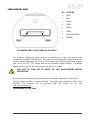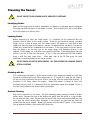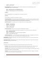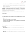
1
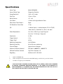
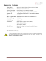
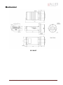
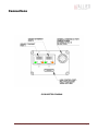
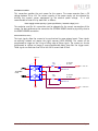
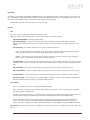
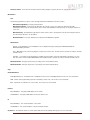
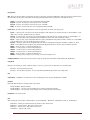
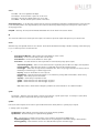
GX3300 / GX3300C
Technical Manual
700060A
Updated 19 January 2010
Allied Vision Technologies Canada Inc.
101-3750 North Fraser Way
Burnaby, BC
V5J 5E9 / Canada
Table of Contents
Table of Contents ......................................................................................................... 2
Introduction ............................................................................................................ 5
Precautions ............................................................................................................. 5
Warranty ................................................................................................................. 5
Specifications .......................................................................................................... 6
Supported Features ................................................................................................... 7
Mechanical .............................................................................................................. 8
Connections............................................................................................................. 9
Cleaning the Sensor ................................................................................................. 15
Adjusting the F-mount ............................................................................................. 16
Network Card Configuration ....................................................................................... 17
GigE Sample Viewer and Filter Driver .......................................................................... 21
Trouble Shooting ..................................................................................................... 22
Addendum .................................................................................................................. 25
GX IO Schematic ...................................................................................................... 26
User Trigger Circuit Example ...................................................................................... 27
TV Zoom Lens Connection ......................................................................................... 28
Video Iris Connection ............................................................................................... 29
Trigger Timing Diagram ............................................................................................ 30
Notes on Triggering ................................................................................................. 31
Camera Controls ...................................................................................................... 33
GX3300 Technical Manual
Page 2
Legal notice
For customers in the U.S.A.
(FCC Compliance Information)
This equipment has been tested and found to comply with the limits for a Class A digital device, pursuant to Part 15 of the FCC
Rules. These limits are designed to provide reasonable protection against harmful interference when the equipment is operated
in a commercial environment. This equipment generates, uses, and can radiate radio frequency energy and, if not installed and
used in accordance with the instruction manual, may cause harmful interference to radio communications. However there is no
guarantee that interferences will not occur in a particular installation. Operation of this equipment in a residential
environment is likely to cause harmful interference.
You are cautioned that any changes or modifications not expressly approved in this manual could void your authority to
operate this equipment. The shielded interface cable recommended in this manual must be used with this equipment in order
to comply with the limits for a computing device pursuant to Subpart B of Part 15 of FCC Rules.
For customers in Canada
This digital apparatus complies with the Class A limits for radio noise emissions set out in the Radio Interference Regulations.
Pour utilisateurs au Canada
Cet appareil numérique est conforme aux normes classe A pour bruits radioélectriques, spécifiées dans le Règlement sur le
brouillage radioélectrique.
Life support applications
These products are not designed for use in life support appliances, devices, or systems where malfunction of these products
can reasonably be expected to result in personal injury. Allied Vision Technologies customers using or selling these products
for use in such applications do so at their own risk and agree to fully indemnify Allied Vision Technologies for any damages
resulting from such improper use or sale.
Trademarks
Unless stated otherwise, all trademarks appearing in this document are the property of Allied Vision Technologies and are fully
protected by law.
Warranty
The information provided by Allied Vision Technologies is supplied without any guarantees or warranty whatsoever, be it
specific or implicit. Also excluded are all implicit warranties concerning the negotiability, the suitability for specific
applications or the non-breaking of laws and patents. Even if we assume that the information supplied to us is accurate, errors
and inaccuracy may still occur.
Copyright
All text, pictures and graphics are protected by copyright and other laws protecting intellectual property. It is not permitted
to copy or modify them for trade use or transfer, nor may they be used on web sites.
Allied Vision Technologies Canada Inc. 1/2010
All rights reserved.
GX3300 Technical Manual
Page 3
Contacting Allied Vision Technologies
• Technical information:
http://www.alliedvisiontec.com
• Support:
[email protected]
Allied Vision Technologies GmbH (Headquarters)
Taschenweg 2a
07646 Stadtroda, Germany
Tel.: +49.36428.677-0
Fax.: +49.36428.677-28
e-mail: [email protected]
Allied Vision Technologies Canada Inc.
101-3750 North Fraser Way
Burnaby, BC, V5J 5E9, Canada
Tel: +1 604-875-8855
Fax: +1 604-875-8856
e-mail: [email protected]
Allied Vision Technologies Inc.
38 Washington Street
Newburyport, MA 01950, USA
Toll Free number +1-877-USA-1394
Tel.: +1 978-225-2030
Fax: +1 978-225-2029
e-mail: [email protected]
GX3300 Technical Manual
Page 4
Introduction
The GX3300 series of cameras are sensitive, 17 frames per second, 8 megapixel, Gigabit
Ethernet cameras based on the Kodak KAI-08050 CCD sensor. These cameras support the use of
1 or 2 gigabit Ethernet ports in a LAG configuration for higher bandwidth requirements.
Precautions
READ INSTALLATION GUIDE CAREFULLY.
This document contains specific information which is necessary for the correct operation and
treatment of this product.
DO NOT OPEN THE CAMERA. WARRANTY IS VOID IF CAMERA IS OPENED.
This camera contains sensitive components which can be damaged if handled incorrectly.
KEEP SHIPPING MATERIAL.
Poor packaging of this product can cause damage during shipping.
VERIFY ALL EXTERNAL CONNECTIONS.
Verify all external connections in terms of voltage levels, power requirements, voltage polarity,
and signal integrity prior to powering this device.
CLEANING.
This product can be damaged by some volatile cleaning agents. Avoid cleaning the image
sensor unless absolutely necessary. Please see instructions on sensor cleaning in this
document.
DO NOT EXCEED ENVIRONMENTAL SPECIFICATIONS.
See environmental specifications limits in the Specifications section of this document.
Warranty
AVT Canada Inc. provides a 2 year warranty which covers the replacement and repair of all
parts which are found to be defective in the normal use of this product. AVT Canada Inc. will
not warranty parts which have been damaged through the obvious misuse of this product.
GX3300 Technical Manual
Page 5
Specifications
Sensor Type
Kodak KAI-08050
Sensor Shutter Type
Progressive Interline
Image Resolution
3296 x 2472 pixels
Pixel Size
5.5μm x 5.5μm
Optical Format
4/3 inch
Lens Mount
F-mount with adjustable back focus
Color Sensor Filter Pattern†
Bayer
Full Resolution Frame Rate
17 fps
I/O
2 isolated inputs, 4 isolated outputs, RS-232 TX/RX,
video auto-iris, motorized iris, focus, and zoom
Power Requirements
Less than 6.1W using a single Gige port
Less than 7.2 W using 2 Gige ports
Digitization
14 Bits
Trigger latency*
1.5μs
Trigger Jitter*
±0.5μs
Operating Temperature
0 to 50 Celsius
Operating Humidity
20 to 80% non-condensing
Size and Weight
See mechanical diagrams
Hardware Interface Standard
IEEE 802.3 1000BASE-T, 100BASE-TX
Software Interface Standard
GigE Vision Standard 1.0
Regulatory
Conforms to CE, FCC, RoHS
†
Applies to GX3300C only.
††
Power consumption will increase with reduced ROI imaging, vertical binning, and color formats.
*
See Notes on Triggering in the Addendum.
***DUE TO THE SMALL PACKAGING AND HIGH SPEED OF THE GX CAMERAS, SPECIAL CARE IS REQUIRED
TO MAINTAIN A REASONABLE OPERATING TEMPERATURE. IF THE CAMERA IS TO BE OPERATED IN A
WARM ENVIRONMENT, IT IS SUGGESTED THAT THE CAMERA BE MOUNTED ON A HEAT SINK SUCH AS A
METAL BRACKET AND THAT THERE IS SUFFICIENT AIR FLOW.
GX3300 Technical Manual
Page 6
Supported Features
Imaging Modes
free-running, external trigger, fixed rate, software trigger
Fixed Rate Control
0.001 fps to maximum frame rate
External Trigger Delay
0 to 60 seconds in 1 microsecond increments
External Trigger Event
rising edge, falling edge, any edge, level high, level low
Exposure Time
10 microseconds to 60 seconds in 1 microsecond increments
Gain
0 to 34dB
Region of Interest (ROI) independent x and y control with 1 pixel resolution***
Horizontal Binning
1 to 8 pixels
Vertical Binning
1 to 8 rows***
Pixel Formats
Mono8, Mono16*, Bayer8, Bayer16, RGB24,
YUV411, YUV422, YUV444,
BGR24, RGBA24, BGRA24
Sync Out Modes
trigger ready, trigger input, exposing, readout, imaging,
strobe, GPO
*On monochrome versions only.
***VERTICAL BINNING AND VERTICAL ROI CAN SIGNIFICANTLY INCREASE THE POWER CONSUMPTION OF
THE CAMERA AND SHOULD ONLY BE USED INTERMITTENTLY AND WITH CAREFUL ATTENTION TO THE
OPERATING TEMPERATURE OF THE CAMERA.
GX3300 Technical Manual
Page 7
Mechanical
GX F-MOUNT
GX3300 Technical Manual
Page 8
Connections
GX CONNECTION DIAGRAM
GX3300 Technical Manual
Page 9
GIGABIT ETHERNET PORTS
These ports conform to the IEEE 802.3 1000BASE-T standard for Gigabit Ethernet over copper.
It is recommended that CAT5E or CAT6 compatible cabling and connectors be used for best
performance. Cable lengths up to 100m are supported. For higher bandwidth requirements,
both ports can be used in a link aggregation group (LAG) configuration.
GENERAL PURPOSE IO PORT
PIN
FUNCTION
1
POWER GROUND
2
EXTERNAL POWER
3
SYNC OUT 4
4
SYNC IN 1
5
SYNC OUT 3
6
SYNC OUT 1
7
USER GROUND
8
RS-232 RXD
9
RS-232 TXD
10
USER VCC
11
SYNC IN 2
12
SYNC OUT 2
GENERAL PURPOSE IO PORT AS SEEN FROM BACK OF
CAMERA
The General Purpose I/O port uses a Hirose HR10A-10R-12PB connector on the camera side.
The mating cable connector is Hirose HR10A-10P-12S. This connector can be purchased from
AVT Canada Inc. or from http://www.digikey.com. An open-ended cable assembly can also be
ordered from AVT Canada Inc. (Part number 02-6033A).
See Addendum for more detail.
POWER GROUND
This is the main ground of the camera circuitry and will be the return path for the external
power source. This connection must be provided to operate the camera. The conductor used
for this connection must be adequate for the current consumption of the camera. For best
performance the connection for POWER GROUND should be physically close to the EXTERNAL
POWER connection.
GX3300 Technical Manual
Page 10
EXTERNAL POWER
This connection provides the main power for the camera. The camera operates from a DC
voltage between 5V to 24V. The current capacity of the power supply can be estimated by
dividing the camera’s power requirement by the external power voltage. It is also
recommended to factor this by about 50% as follows:
Power supply current capacity = (power specification / external voltage) x 1.5
The conductor used for this connection must be adequate for the current consumption of the
camera. For best performance the connection for EXTERNAL POWER should be physically close to
the POWER GROUND connection.
SYNC INPUTS (1 and 2)
The input signals allow the camera to be synchronized to some external event. These signals
are optically isolated and require the signal common (USER GROUND). The camera can be
programmed to trigger on the rising or falling edge of these signals. The camera can also be
programmed to capture an image at some programmable delay time after the trigger event.
These signals can be driven from 5V to 24V with a current load of 5mA.
VCC
8
VDD+3.3
1
180R
1/10W
S
7
G
2
TO CAMERA
LOGIC
D
5V TO 24V
IF = 5mA
PIN 4. SY NC IN 1
MMBF4393LT1G
3
6
4
180R
1/10W
S
HCPL-063L
5
GND
G
D
5V TO 24V
IF = 5mA
PIN 11. SY NC IN 2
MMBF4393LT1G
PIN 7. USER GND
GX3300 Technical Manual
Page 11
SYNC OUTPUTS (1 to 4)
These signals are optically isolated and require the user to provide a high voltage level (USER
VCC) and signal common (USER GROUND). USER VCC can be from 5V to 24V. ICC is a function of
USER VCC and load resistor R. An example of the functional circuit is indicated in the following
diagram.
CAMERA
CIRCUIT
USER TRIGGER
CIRCUIT
5V TO 24V
VCC-USER
PIN 10. USER VCC
IF = 5mA
3.3V CAMERA
LOGIC SIGNAL
16
1
442R
100K
2
15
SY NC OUT
V LOAD
TLP281-4GB
R
GND-USER
CAMERA
LOGIC SIGNAL
SYNC OUT
SIGNAL
T3
T1
T2
T4
Various USER VCC values and load values for the above circuit are indicated in the following
table:
USER
VCC
USER
ICC
R
LOAD
V LOAD
R POWER
DISSIPATION
5V
8mA
500Ω
4.1V
32mW
1.5μs 6.5μs 2μs 14μs
5V 4.8mA 1KΩ
4.8V
23mW
1.5μs
12V 9.2mA 1.2KΩ
11.2V
101mW
1.5μs 11.2μs 2μs 20μs
12V 4.9mA 2.4KΩ
11.8V
58mW
1.5μs 8.5μs 17μs 55μs
24V 9.5mA 2.4KΩ
23.2V
217mW
1.5μs 22μs
24V 5mA 4.8KΩ
23.8V
120mW
1.5μs 12μs 17μs 105μs
GX3300 Technical Manual
T1
T2
5μs
T3
T4
17μs 40μs
2μs 37μs
Page 12
These signals only function as outputs and can be configured as follows:
Exposing
Corresponds to when camera is
integrating light.
Trigger Ready
Indicates when the camera will accept
a trigger signal.
Trigger Input
A relay of the trigger input signal used
to “daisy chain” the trigger signal for
multiple cameras.
Readout
Valid when camera is reading out data.
Strobe
Programmable pulse based on one of
the above events.
Imaging
Valid when camera is exposing or
reading out.
GPO
User programmable binary output.
Any of the above signals can be set for active high or active low.
RS-232 RXD and RS-232 TXD
These signals are RS-232 compatible. These signals allow communication from the host system
via the Ethernet port to a peripheral device connected to the camera. These signals are not
optically isolated and reference power ground. If these signals are used in the system, care
must be taken to prevent ground loop problems.
USER GROUND
This connection provides the user ground reference and return path for the isolated sync in
and sync out signals. This connection is necessary if any of the isolated sync signals are to be
used. It is also recommended that this ground connection be physically close to the used sync
signals to prevent parasitic coupling. For example, a good cable design would connect the
required signal on one conductor of a twisted pair and the isolated ground on the second
conductor of the same twisted pair.
USER VCC
This connection provides the power supply for the isolated sync out signals. The voltage
requirement is from 5V to 24V DC. The current requirement for this supply is a function of the
optical isolator collector current and the number of sync outs used in the system. See the SYNC
OUTPUT section for more detail. To prevent parasitic coupling this connection should be
physically close to the used SYNC OUT signals and USER GROUND.
GX3300 Technical Manual
Page 13
LENS CONTROL PORT
PIN
FUNCTION
1
IRIS +
2
IRIS -
3
FOCUS +
4
FOCUS -
5
ZOOM +
6
ZOOM -
7
AUTO IRIS SIGNAL
8
GROUND
LENS CONTROL PORT AS SEEN FROM BACK OF CAMERA
This connector provides the signals necessary to control the iris, focus, and zoom of most
commercially available TV Zoom lenses. The camera can be configured to operate lenses with
unipolar voltage requirements of 6V up to 12V or lenses which operate with bipolar voltages
from ±6V up to ±12V. This voltage level can be controlled through software. The default
voltage will be set to 6V. The current capacity for each axis is 50mA.
CARE MUST BE TAKEN NOT TO EXCEED THE LENS MANUFACTURERS VOLTAGE
SPECIFICATION.
This connector also provides the signals necessary to operate a video auto iris type of lens.
The lens control connector is a Hirose 3260-8S3. The mating cable connector is Hirose 32408P-C(50). This connector can be purchased from AVT Canada Inc. or from
http://www.digikey.com.
See Addendum for more detail.
GX3300 Technical Manual
Page 14
Cleaning the Sensor
DO NOT CONTACT CLEAN SENSOR UNLESS ABSOLUTELY NECESSARY.
Identifying Debris
Debris on the image sensor or optical components will appear as a darkened area or smudge on
the image that does not move as the camera is moved. Do not confuse this with a pixel defect
which will appear as a distinct point.
Locating Debris
Before attempting to clean the image sensor, it is important to first determine that the
problem is due to debris on the sensor window. To do this you should be viewing a uniform
image, such as a piece of paper, with the camera. Debris will appear as a dark spot or dark
region that does not move as the camera is moved. To determine that the debris is not on the
camera lens, rotate the lens independent of the camera. If the spot moves as the lens moves,
then the object is on the lens -not on the image sensor- and therefore cleaning is not
required. If the camera has an IR filter, then rotate the IR filter. If the object moves then the
particle is on the IR filter not the sensor. If this is the case remove the IR filter carefully
using a small flat head screw driver.
Clean both sides of the IR filter using the same
techniques as explained below for the sensor window.
DO NOT TOUCH ANY OPTICS WITH FINGERS. OIL FROM FINGERS CAN DAMAGE FRAGILE
OPTICAL COATINGS.
Cleaning with Air
If it is determined that debris is on the sensor window, then remove the camera lens, and blow
the sensor window directly with clean compressed air. If canned air is used, do not shake or
tilt the can prior to blowing the sensor. View a live image with the camera after blowing. If
the debris is still there, repeat this process. Repeat the process a number of times with
increased intensity until it is determined that the particulate cannot be dislodged. If this is
the case then proceed to the contact cleaning technique.
Contact Cleaning
Only use this method as a last resort. Use 99% laboratory quality isopropyl alcohol and clean
cotton swabs. Dampen the swab in the alcohol and gently wipe the sensor in a single stroke.
Do not reuse the same swab. Do not wipe the sensor if the sensor and swab are both dry. You
must wipe the sensor quickly after immersion in the alcohol, or glue from the swab will
contaminate the sensor window. Repeat this process until the debris is gone. If this process
fails to remove the debris, then contact AVT Canada Inc.
GX3300 Technical Manual
Page 15
Adjusting the F-mount
THE F-MOUNT IS ADJUSTED AT THE FACTORY AND SHOULD NOT REQUIRE ADJUSTING.
If for some reason, the F-mount requires adjustment, use the following method.
Attach F-mount compatible lens
Use an F-mount compatible lens that allows an infinity focus. Attach the lens to the camera
using a counter-clockwise rotation of about a quarter turn. The lens should snap into place
and the lens flange and camera flange should mate over the full circumference.
Loosen F-MOUNT FRONT ASSEMBLY
Use a 1.5mm hex wrench to loosen the 3 set screws which hold the F-mount front assembly to
the camera body.
Image to Infinity
Set the lens to infinity and image a distant object. The distance required will depend on the
lens used but typically 30 to 50 feet should suffice. Gently move the F-mount front assembly
until the image is in focus. Carefully tighten the 3 set screws. Recheck the focus.
GX3300 Technical Manual
Page 16
Network Card Configuration
Operating GigE Vision GX cameras using multiple network adaptors
The GX series cameras offer two Gigabit Ethernet ports for image data transfer and control. Users can
connect one or both ports on the GX to Ethernet adapter ports on a host computer. Connecting both
ports will increase the available bandwidth to 240 MB/sec, allowing higher frame rates and resolutions
than a single port connection.
GX cameras can be operated in single port and dual port configurations. The dual port approach
requires the host computer to configure a Link Aggregate Group (LAG). A LAG configuration combines
multiple Ethernet ports into a single data channel.
1. Install a dual port network card in the host computer. To achieve full camera performance, you
should use a Gigabit Ethernet card that supports "Jumbo frames" of at least 9KB size.
2. Once installed, open your “Network Connections” (Start -> Control Panel->Network
Connections) and right-click on one of the two network connection corresponding to the card
that was just installed.
3. Select “Properties” from the contextual menu that
appears when you right click the network connection
icon. This will open the properties window.
4. In the properties window, click the “Configure” button. Select the “Advanced” tab. In the
“Property” list make the following changes:
(a) select “Jumbo Frames” and change the value to 9014 bytes or higher.
(b) select “Receive Descriptors” on the same list and change the value to 512
(c) select "Performance Options" and set "Interrupt Moderate Rate" to "Extreme"
GX3300 Technical Manual
Page 17
5. Click on “OK” to validate your change (the “Properties” window will close). The Property list
will be different between different types/brands of gigabit Ethernet interface cards. If "Jumbo
Frames" does not appear in this list, then your card probably does not support it. If your card
does not support Jumbo Frames, then your CPU usage will be higher.
6. Re-open the "Properties" of the PRO/1000 GT adapter by right-clicking the Local Area
Connection "Intel® PRO/1000 GT" network connection icon in the Network Connections
window and select the "Advanced" tab at the top of the Properties dialog.
7. In the "Windows Firewall" section, select "Settings". In the
Settings dialog choose "Off" to turn off the Windows firewall.
The camera will not work if the firewall is active. If you
installed the AVT/Prosilica GigE filter driver, this step is not
required.
8. Perform Steps 1 – 8 for the other Ethernet adapter port that will be dedicated to the GX camera
network.
9. The next section will provide instructions for configuring the Link Aggregate Group (LAG) to
combine the two ports dedicated to the GX network.
Open your “Network Connections” (Start -> Control Panel->Network Connections) and rightclick on one of the two network connection corresponding to the card that was just installed.
Select “Properties” from the contextual menu that appears when you right click the network
connection icon. This will open the properties window. In the properties window, click on
“Configure” button in order to create a Link Aggregate Group (LAG) between the two ports.
10. Select the “Teaming” tab (analogous to LAG), enable
“Team this adapter with other adapters and click on the
“New Team” button.
11. Specify a name for the Team (Link Aggregate Group). This
should be something that will distinguish this adapter
from others in your system. Click “Next” to continue.
GX3300 Technical Manual
Page 18
12. Select the two Ethernet ports to which the GX
camera will be connected. These ports will form
our LAG or TEAM. Click “Next” to continue.
13. Choose “Static Link Aggregation”. Click “Next” to
continue.
14. The LAG group will now be configured. You may be
asked to permit the “AVT_Prosilica GigE Vision Filter
Miniport” installation on the new LAG adapter. Click
“Continue Anyway”.
GX3300 Technical Manual
Page 19
15. Once completed the properties of the TEAM (LAG) that has just been created will appear. A
new Network Connections Icon corresponding to the LAG group is created. You have now
completed the Link Aggregate Group configuration.
16. Reboot the system and install GigE Sample Viewer.
GX3300 Technical Manual
Page 20
GigE Sample Viewer and Filter Driver
o Download GigE Sample Viewer from www.alliedvisiontec.com. This will install the Sample
Viewer application program, drivers, and optionally the AVT/Prosilica Filter Driver. The
Filter Driver will improve CPU performance and is recommended.
o Plug in the GX camera Ethernet cable(s) and power. Verify that the Green LED is a solid
green. Run Sample Viewer. It will take a few seconds for the camera to be recognized,
especially if your camera is in DHCP mode. If the camera does not appear after one
minute, see the Trouble Shooting section of this document.
o In Sample Viewer, select the wrench icon to change camera settings. See the Camera
Controls Addendum for description of each setting. Select the eye icon to stream images. If
the camera is not imaging, see the Trouble Shooting section of this document.
Figure 1. GigE Viewer application window.
GX3300 Technical Manual
Page 21
Trouble Shooting
Is the camera getting power?
The Green LED is the camera power indicator. If unlit, check the power adaptor. If possible,
swap with one that is known to work. If using a custom power adaptor, be sure the adaptor
supports the voltage and power requirements of the camera . If the LED still does not light up,
contact AVT Canada Inc. support.
Is the camera powered, but not detected in SampleViewer?
Damaged or poor quality Ethernet cabling can result in no cameras found, dropped packets,
decreased bandwidth, and other problems. Use Cat5e or better cabling known to work.
Configure your NIC as outlined in “Gigabit Ethernet Setup For Windows”. It should have an IP
address of 169.254.x.x, Subnet Mask: 255.255.0.0. This is the AutoIP address range. If your
NIC has no access to a DHCP server, the camera will still be auto assigned an IP address. There
should be no gateway on your NIC.
Connect a single camera directly to your NIC, no hub/switch, and run the prosilica IP
Configuration
utility
(Start>Programs>Prosilica>GigEIPConfig
or
C:\Program
Files\Prosilica\GigEViewer\ipconfig.exe). You may need to wait up to 30 sec for camera to
appear.
A camera in DHCP (AutoIP fallback) mode.
•
Camera is listed: Your camera and NIC must be on the same subnet, e.g.: NIC: IP
169.254.23.2 Subnet Mask: 255.255.0.0, Camera IP: 169.254.43.3 Subnet Mask: 255.255.0.0.
The following example is not on the same Subnet: NIC IP 169.250.23.2 Subnet Mask:
255.255.255.0, CamIP 169.254.13.0 Subnet Mask: 255.255.0.0. This can happen if you use a
GX3300 Technical Manual
Page 22
non AutoIP range on your NIC and it doesn’t have access to a DHCP server. Either change your
NIC IP to be in the AutoIP range, or fix the camera IP address to be on the same subnet as
your NIC.
•
Camera is not listed, or flashing “Camera Unavailable”: There may be multiple NICs on
your system set to the same subnet. The camera can not know which card to resolve to. Change
the IP address of your NIC.
If you are still having problems, type: ipconfig /all in a windows command prompt, and send a
screenshot to [email protected].
Ipconfig /all screenshot
Is the camera listed in SampleViewer but can’t acquire images?
Reset your camera settings to factory default: with ConfigFileIndex = Factory, click the
ConfigFileLoad button.
While streaming, check your Stats:
All stats 0 while streaming. Firewall likely blocking traffic
GX3300 Technical Manual
Page 23
•
•
•
All stats 0. Likely a firewall is blocking incoming traffic. Disable your firewall. Check your
camera trigger settings. Many camera trigger modes require a software or hardware trigger
event to capture frames.
Packets are incoming, but all dropping. Be sure you have JumboFrames enabled on your NIC.
Otherwise, decrease your PacketSize setting to 1500.
All packets completing as normal, but black image. Check ExposureValue, ExposureMode, and
be sure your scene is suitably lit.
If you are still having problems acquiring images, please send your camera settings file (click on
the disk icon in SampleViewer) to [email protected].
Saving camera setting file
GX3300 Technical Manual
Page 24
Addendum
GX3300 Technical Manual
Page 25
GX3300 Technical Manual
CAMERA LOGIC SY NC OUT 4
CAMERA LOGIC SY NC OUT 3
CAMERA LOGIC SY NC OUT 2
CAMERA LOGIC SY NC OUT 1
3.3V LOGIC
CAMERA LOGIC SY NC IN 2
CAMERA LOGIC SY NC IN 1
4
6
GND
VCC
100K
100K
100K
IF = 5mA
442R
IF = 5mA
442R
IF = 5mA
442R
IF = 5mA
6
3
442R
4.7K
7
100K
4.7K
1
NC7WZ14P6X
VDD+3.3
5
2
8
7
6
5
4
3
2
1
4
3
2
1
TLP281-4GB
TLP281-4GB
TLP281-4GB
9
10
11
12
13
14
15
16
HCPL-063L
TLP281-4GB
GND
VCC
VDD+3.3
8
5
VDD+3.3
G
S
SYNC OUT 4
SYNC OUT 3
SYNC OUT 2
MMBF4393LT1G
D
5V TO 24V
IF = 5mA
MMBF4393LT1G
G
5V TO 24V
IF = 5mA
D
S
SYNC OUT 1
180R
1/10W
180R
1/10W
PIN
PIN
PIN
PIN
PIN
PIN
PIN
PIN
PIN
PIN
PIN
PIN
1. POWER GROUND
2. EXTERNAL POWER
3. SYNC OUT 4
4. SYNC IN 1
5. SYNC OUT 3
6. SYNC OUT 1
7. USER GROUND
8. RS-232 RXD
9. RS-232 TXD
10. USER VCC
11. SY NC IN 2
12. SY NC OUT 2
4
1
5
11
10
12
9
6
8
7
HIROSE HR10A-10R-12PB
3
2
GX IO Schematic
Page 26
GX3300 Technical Manual
USER
USER
USER
USER
LOGIC
LOGIC
LOGIC
LOGIC
SY NC
SY NC
SY NC
SY NC
OUT 1
OUT 2
OUT 3
OUT 4
USER LOGIC SY NC IN 2
USER LOGIC SY NC IN 1
5V POWER
CIRCUIT
CAMERA POWER
9
7
5
3
2
4
6
8
1OE
2OE
VCC
GND
2A1
2A2
2A3
2A4
1Y 1
1Y 2
1Y 3
1Y 4
1
19
20
10
11
13
15
17
18
16
14
12
SN74ABT244APWR
2Y 1
2Y 2
2Y 3
2Y 4
1A1
1A2
1A3
1A4
VDD+5
0.1u
10V
VDD+5
1K
1K
1K
1K
1
2
3
4
5
6
7
8
9
10
11
12
6
9
12
1
11
5
10
4
3
2
HIROSE HR10A-10P-12S
7
8
CABLE SIDE
NOTES:
1. CAMERA POWER = 5V TO 24V
2. CAMERA POWER DOES NOT NEED TO BE THE SAME AS USER VCC.
3. CAMERA GND DOES NOT NEED TO CONNECT TO USER GND.
4. USER VCC MUST HAVE CURRENT CAPACITY TO SUPPLY IC
CURRENT FOR EACH SYNC OUT USED.
USER VCC
SY NC IN 2
SY NC OUT 2
POWER GROUND
EXTERNAL POWER
SY NC OUT 4
SY NC IN 1
SY NC OUT 3
SY NC OUT 1
USER GND
User Trigger Circuit Example
This diagram indicates one example of a 5V TTL based user trigger circuit.
Page 27
GX3300 Technical Manual
COMMON
IRIS
FOCUS
ZOOM
COMMON
IRIS-
IRIS+
FOCUS-
FOCUS+
NOTES:
1. CURRENT CAPACITY PER AXIS = 50mA.
2. VERIFY LENS VOLTAGE SETTING ON CAMERA DOES NOT EXCEED LENS VOLTAGE SPECIFICATION.
TV ZOOM LENS
UNIPOLAR TYPE
TV ZOOM LENS
BIPOLAR TYPE
ZOOM-
ZOOM+
COMMON
COMMON
COMMON
8
6
4
2
8
COMMON
COMMON
6
4
2
ZOOM-
FOCUS-
IRIS-
HIROSE 3240-8P-C(50)
7
5
3
1
HIROSE 3240-8P-C(50)
7
5
3
1
ZOOM
FOCUS
IRIS
ZOOM+
FOCUS+
IRIS+
TV Zoom Lens Connection
Page 28
POWER GROUND
12V_POWER
VIDEO
AUTO-IRIS
LENS
GX3300 Technical Manual
1
2
3
4
JEITA CONNECTOR
1
2
3
4
VIDEO SIGNAL
LENS GROUND
LENS POWER
POWER GROUND
12V POWER
1
2
3
4
5
6
7
8
9
10
11
12
6
12
1
11
5
10
4
3
2
7
5
3
1
HIROSE 3240-8P-C(50)
8
6
4
2
HIROSE HR10A-10P-12S
7
8
9
Video Iris Connection
Page 29
Trigger Timing Diagram
GX3300 Technical Manual
Page 30
Notes on Triggering
Definitions
o User Trigger is the trigger signal applied by the user.
o Logic Trigger is the trigger signal seen by the camera internal logic.
o Tpd is the propagation delay between the User Trigger and the Logic Trigger.
o Exposure is high when the camera image sensor is integrating light.
o Readout is high when the camera image sensor is reading out data.
o Trigger Latency is the time delay between the User Trigger and the start of Exposure.
o Trigger Jitter is the error in the Trigger Latency time.
o Trigger Ready indicates to the user that the camera will accept the next trigger.
o Registered Exposure Time is the Exposure Time value currently stored in the camera
memory.
o Expose Start Delay is the delay time from the start of Exposure to valid Trigger Ready. It is
the Registered Exposure Time subtracted from the Readout time and indicates when the
next Exposure cycle can begin such that the Exposure will end after the current Readout.
o Interline Time is the time between sensor row readout cycles.
o Imaging is high when the camera image sensor is either exposing and/or reading out data.
o Idle is high if the camera image sensor is not exposing and/or reading out data.
Rules
o The User Trigger pulse width should be at least three times the width of the Trigger
Latency as indicated in the Specifications section of this document.
o The end of Exposure will always trigger the next Readout.
o The end of Exposure must always end after the current Readout.
o The start of Exposure must always correspond with the Interline Time if Readout is true.
o Expose Start Delay equals the Readout time minus the Registered Exposure Time.
Triggering during the Idle State
o For applications requiring the shortest possible Trigger Latency and the smallest possible
Trigger Jitter the User Trigger signal should be applied when Imaging is false and Idle is
true.
o In this case, Trigger Latency and Trigger Jitter are as indicated in the Specifications
section.
GX3300 Technical Manual
Page 31
Triggering during the Readout State
o For applications requiring the fastest triggering cycle time whereby the camera image
sensor is exposing and reading out simultaneously, then the User Trigger signal should be
applied as soon as a valid Trigger Ready is detected.
o In this case, Trigger Latency and Trigger Jitter can be up to 1 line time since Exposure
must always begin on an Interline boundary.
GX3300 Technical Manual
Page 32
Camera Controls
Note: Not all features listed here are available on all camera models.
Acquisition
This group of controls relates to the acquiring of images.
Trigger
This group of controls relates to how an image frame is initiated or triggered.
AcqEnd
AcqEndTriggerEvent – What type of external input trigger will end acquisition.
EdgeRising – rising edge trigger
EdgeFalling – falling edge trigger
EdgeAny – rising or falling edge
LevelHigh – active high signal
LevelLow – active low signal
AcqEndTriggerMode – Selects if the end of acquisition should be stimulated by an external hardware trigger. See the
AcquisitionStop command for software triggering.
SyncIn1 – trigger at SyncIn1 to be associated with this control
SyncIn2 – trigger at SyncIn2 to be associated with this control
Disabled – an external trigger does not control end of acquisition
AcqRec
An AcqStart hardware trigger signal, or the AcquisitionStart command, must be received before your AcqRec trigger. See
AcquisitionMode = Recorder.
AcqRecTriggerEvent – What kind of external input trigger will start a recording sequence when AcquisitionMode set to Recorder.
EdgeRising – rising edge trigger
EdgeFalling – falling edge trigger
EdgeAny – rising or falling edge
LevelHigh – active high signal
LevelLow – active low signal
AcqRecTriggerMode – Selects if the start of a Recorder event should be stimulated by an external hardware trigger. There is no
software trigger event capability for this mode.
SyncIn1 – trigger at SyncIn1 to be associated with this control
SyncIn2 – trigger at SyncIn2 to be associated with this control
Disabled – an external trigger does not control the start of a Recorder event
AcqStart
AcqStartTriggerEvent – What kind of external input trigger will stimulate the start of acquisition.
EdgeRising – rising edge trigger
EdgeFalling – falling edge trigger
EdgeAny – rising or falling edge
GX3300 Technical Manual
Page 33
LevelHigh – active high signal
LevelLow – active low signal
AcqStartTriggerMode - Selects if the start of acquisition should be stimulated by an external hardware trigger. See the
AcquisitionStart command for software triggering.
SyncIn1 – trigger at SyncIn1 to be associated with this control
SyncIn2 – trigger at SyncIn2 to be associated with this control
Disabled – an external trigger does not control start of acquisition
FrameRate
When FrameStartTriggerMode is set to FixedRate, this control specifies the frame rate.
FrameStart
Controls relating to the triggering of frames within an acquisition.
FrameStartTriggerDelay - Start-of-image is delayed FrameStartTriggerDelay microseconds after receiving an external trigger event.
This feature valid only when FrameStartTriggerMode is set to external trigger (i.e. SyncIn1, SyncIn2). Useful when using a common
trigger to synch with a strobe lighting source, which will inherently have some fixed setup time.
FrameStartTriggerEvent - The external trigger can be configured to accept various trigger event types:
EdgeRising – rising edge trigger
EdgeFalling – falling edge trigger
EdgeAny – rising or falling edge
LevelHigh – active high signal
LevelLow – active low signal
FrameStartTriggerMode - Determines how an image frame is initiated within an acquisition.
Freerun – camera runs at maximum supported frame rate depending on the exposure time and region of interest size.
SyncIn1 - external trigger SyncIn1
SyncIn2 - external trigger SyncIn2
FixedRate - camera self-triggers at a fixed frame rate defined by FrameRate.
Software - software initiated image capture.
FrameStartTriggerSoftware – A command. Valid when FrameStartTriggerMode equals Software. In SampleViewer, when selected a
button appears at the bottom of the controls window that snaps a single image when pressed.
AcquisitionAbort – A command. In SampleViewer, when selected a button appears at the bottom of the controls window that aborts
the acquisition when pressed.
AcquisitionFrameCount - Define the number of frames to capture when capturing a limited sequence of images. Used in combination
with MultiFrame and Recorder acquisition modes.
AcquisitionMode
The acquisition modes, which determine how the camera handles frame triggers within the acquisition stream.
Continuous – After an acquisition start event, the camera will continuously receive frame trigger events, or in the case where
FrameStartTriggerMode equals Freerun, will continuously stream. This is the normal acquisition mode of the camera.
SingleFrame - After an acquisition start event, the camera will only receive a single frame trigger event. Further trigger events will
be ignored until acquisition is stopped and restarted.
MultiFrame - After an acquisition start event, the camera will receive AcquisitionFrameCount number of triggers. Further trigger
events will be ignored until acquisition is stopped and restarted.
GX3300 Technical Manual
Page 34
Recorder – After an acquisition start event, the camera will continuously capture images into the camera on-board memory, but
will not send them to the host until an AcqRec trigger signal is received. Further AcqRec trigger events will be ignored until
acquisition is stopped and restarted.
Combined with the RecorderPreEventCount control, this feature is useful for returning any number of frames before a trigger event.
When AcqRec trigger is received, the currently imaging/aquiring image will complete as normal, and then at least one more image
will be taken. See RecorderPreEventCount.
The memory is a circular buffer, that is, once it is full starts rewriting images. Its size is determined by AcquisitionFrameCount.
AcquisitionStart – A command. In SampleViewer, when selected a dialog box appears at the bottom of the controls screen showing an
AcquisitionStart button which will start the camera imaging when pressed.
AcquisitionStop - A command. In SampleViewer, when selected a dialog box appears at the bottom of the controls screen showing an
AcquisitionStop button which will stop the image stream when pressed.
RecorderPreEventCount – The number of images returned before the AcqRec trigger event, with AquisitionFrameCount minus
RecorderPreEventCount images being returned after the trigger event. Valid only when AcquisitionMode equals Recorder.
NOTE: at least one image must be captured after the AcqRec trigger event. That is, you cannot set RecorderPreEventCount = 1,
AcquisitionFrameCount = 1.
ConfigFile
Prosilica's GigE cameras are capable of storing a number of user-specified configurations within the camera's non-volatile memory. These
saved configurations can be used to define the power-up settings of the camera or to quickly switch between a number of predefined
settings.
ConfigFileIndex - The index number corresponding to the configuration set that you are currently working with. Possible settings:
Factory, 1, 2, 3, 4, 5.
ConfigFileLoad – A command. In SampleViewer, selecting this control will reveal a button at the bottom of the controls list that,
when pressed, will load the configuration corresponding to ConfigFileIndex.
ConfigFilePowerUp - The saved configuration that will load when the camera powers up. Possible settings: Factory, 1, 2, 3, 4, 5.
ConfigFileSave - A command. In SampleViewer, selecting this control will reveal a button at the bottom of the controls list that,
when pressed, will save the current camera settings into the non-volatile memory location currently indicated by ConfigFileIndex.
The Factory setting cannot be overwritten.
Controls
DSP
The automatic exposure, gain, and whitebalance features can be configured to respond only to a subregion within the image scene. This
feature can be used to choose a subregion that will 'meter' the rest of the image. This feature works like the region metering on a
photographic camera.
DSPSubregionBottom - defines the bottom of the region in pixels. Defaults to a huge number much larger than the maximum
number of sensor rows.
DSPSubregionLeft - defines the position of left edge of the DSP subregion. Measured in pixels from the left edge. Defaults to zero.
DSPSubregionRight - defines the position of the right edge of the DSP subregion as measured from the left side of the image.
Defaults to a huge number much larger than the maximum number of sensor columns.
DSPSubregionTop - Defines the top edge of the DSP subregion defined as the number of pixels from the top edge of the full image.
Defaults to zero.
GX3300 Technical Manual
Page 35
DefectMask
This feature is only available on the GE4000 and GE4900 cameras. The standard model of these cameras use Class 2 sensors which can
have column defects. The DefectMask replaces defective columns with interpolated values based on neighboring columns. Class 1 and
Class 0 sensors are available for these cameras which do not require any column masking.
DefectMaskColumnEnable - The defect mask can be set to On or Off.
Exposure
Auto
This group of controls relates to the camera auto-exposure function.
NOTE: The camera must be acquiring images in order for the auto exposure algorithm to update.
ExposureAutoAdjustDelay – Currently unimplemented.
ExposureAutoAdjustTol – In percent. A threshold. Sets a range in variation from ExposureAutoTarget in which the
autoexposure algorithm will not respond. Can be used to limit exposure setting changes to only larger variations in scene
lighting.
ExposureAutoAlg – The following algorithms can be used to calculate auto-exposure:
Mean – The arithmetic mean of the histogram of the current image is compared to ExposureAutoTarget, and the next
image adjusted in exposure time to meet this target. Bright areas are allowed to saturate.
FitRange – The histogram of the current image is measured, and the exposure time of the next image is adjusted so
bright areas are not saturated. Generally, the Mean setting is preferred.
ExposureAutoMax – In microseconds. This sets the upper bound to the exposure setting in autoexposure mode. This is useful
in situations where frame rate is important. This value would normally be set to something less than 1x10^6/(desired frame
rate).
ExposureAutoMin - In microseconds. This sets the lower bound to the exposure setting in autoexposure mode.
ExposureAutoOutliers – In percent. The percentage of image pixels that do not have to fit into the proper exposure range.
ExposureAutoRate – In percent. Determines the rate at which the autoexposure function changes the exposure setting.
ExposureAutoTarget – In percent. Controls the general lightness or darkness of the auto exposure feature; specifically the
target mean histogram level of the image, 0 being black, 100 being white.
ExposureMode
Manual - The camera exposure time is fixed by ExposureValue parameter.
Auto - The exposure time will vary continuously according to the scene illumination. The Auto exposure function operates
according to the Auto and DSP controls
AutoOnce - The exposure will be set once according to the scene illumination and then remain at that setting even when the
scene illumination changes. The AutoOnce exposure function operates according to the Auto and DSP controls
External - When ExposureMode is set to External the exposure time will be controlled by an external signal appearing on
SyncIn1 or SyncIn2. In order for this feature to work, the parameter FrameStartTriggerMode must be set to SyncIn1 or
SyncIn2. This feature is supported in version 1.36 firmware and above. It is not available on any of the CMOS-based cameras.
ExposureValue – In microseconds. The sensor integration time. 15000 corresponds to 15 ms integration time, 1000 corresponds to
1ms, etc.
GX3300 Technical Manual
Page 36
Gain
Auto
This group of controls relates to the camera auto gain function.
NOTE: The camera must be acquiring images in order for the auto gain algorithm to update.
GainAutoAdjustDelay – Currently unimplemented.
GainAutoAdjustTol - In percent. A threshold. Sets a range in variation from GainAutoTarget in which the auto gain algorithm
will not respond. Can be used to limit gain setting changes to only larger variations in scene lighting.
GainAutoMax – In dB. Sets the upper bound to the gain setting in Auto gain mode.
GainAutoMin – In dB. Sets the lower bound to the gain setting in Auto gain mode. Normally this number would be set to
zero.
GainAutoOutliers - In percent. The percentage of image pixels that do not have to fit into the auto gain range
GainAutoRate - In percent. Determines the rate at which the auto gain function changes the gain setting.
GainAutoTarget - In percent. Controls the general lightness or darkness of the Auto gain feature. A percentage of the
maximum GainValue.
GainMode
Manual - The camera gain is fixed by GainValue parameter.
Auto - The gain will vary continuously according to the scene illumination. The Auto gain function operates according to the
Auto and DSP controls. Available on cameras with version 1.36 firmware and above.
AutoOnce - The gain will be set once according to the scene illumination and then remain at that setting even when the scene
illumination changes. The AutoOnce gain function operates according to the Auto and DSP controls
GainValue – In dB. GdB = 20 log10(Vin/Vout). The gain setting applied to the sensor. Default gain is zero, and gives the best image
quality. However, in low light situations, it may be necessary to increase the gain setting.
Iris
All video-type auto iris lenses have a default reference voltage. When a voltage larger than this reference voltage is applied to the lens,
the iris closes. When a voltage is applied less than this reference voltage, the iris opens. The auto iris algorithm calculates the
appropriate voltage, IrisVideoLevel, to apply to the lens, based on the brightness of the current image vs. the IrisAutoTarget.
NOTE: The camera must be acquiring images in order for the auto iris algorithm to update.
IrisAutoTarget – In percent. Controls the general lightness or darkness of the auto iris feature; specifically the target mean
histogram level of the image, 0 being black, 100 being white.
IrisMode – Sets the auto-iris mode
Disabled – Turn off the video auto-iris function.
Video – Turn on the video auto-iris function.
VideoOpen – Fully open the iris.
VideoClosed – Full close the iris.
IrisVideoLevel – In 10 mV units. This attribute reports the strength of the video signal coming from the camera.
IrisVideoLevelMax - In 10 mV units. Limits the maximum driving voltage for closing the lens iris. Typically this will be 150,
however it may vary dependent on the lens reference voltage.
GX3300 Technical Manual
Page 37
IrisVideoLevelMin - In 10 mV units. Limits the minimum driving voltage for opening the lens iris. Typically this will be 0.
WhiteBalance
Auto
The following parameters are used to control the way that the Auto whitebalance function operates.
WhitebalAutoAdjustDelay - Currently unimplemented.
WhitebalAutoAdjustTol - A threshold. This parameter sets a range of scene color changes in which the automatic
whitebalance will not respond. This parameter can be used to limit whitebalance setting changes to only larger variations in
scene color.
WhitebalAutoAlg - The whitebalance algorithm is fixed as "Mean", that is, the algorithm uses the mean histogram value for
the red and blue channels in its calculations.
WhitebalAutoRate - In percent. Determines how fast the Auto Whitebalance updates.
WhitebalMode
Manual – Auto whitebalance is off. Whitebalance can be adjusted directly by changing the WhitebalValueRed and
WhitebalValueBlue parameters.
Auto - Whitebalance will continuously adjust according to the current scene. The Auto function operates according to the Auto
and DSP controls
AutoOnce – A command (of type Enumeration in PvAPI). A single iteration of the auto whitebalance algorithm is run, and
then the camera reverts to Manual WhitebalMode. The AutoOnce function operates according to the Auto and DSP controls
WhitebalValueRed – Red gain expressed as a percentage of the camera default setting.
WhitebalValueBlue - Blue gain expressed as a percentage of the camera default setting.
GigE
BandwidthCtrlMode
StreamBytesPerSecond - The default mode of bandwidth control. See the StreamBytesPerSecond control for more information.
SCPD - Stream channel packet delay expressed in timestamp counter units. This mode is not recommended.
Both - Implements a combination of control modes. This mode is not recommended
Ethernet
DeviceEthAddress - The physical MAC address of the camera
HostEthAddress - The physical MAC address of the host network card
IP
DeviceEthAddress - The current IP address of the camera
HostEthAddress - The current IP address of the host network interface.
GvcpRetries - The maximum number of resend requests that the host will attempt when trying to recover a lost packet.
GX3300 Technical Manual
Page 38
HeartbeatInterval – In milliseconds. The interval at which the API sends a heartbeat command to the camera. Normally this parameter
does not require adjustment.
HeartbeatTimeout - In milliseconds. The maximum amount of time the camera will wait for a heartbeat command before timing out.
NOTE: this value may need to be increased when using breakpoints in your API code. Breakpoints stall the API from sending heartbeat
commands, which may cause the camera to time out.
Multicast
Multicast mode allows the camera to send image data to all hosts on the same subnet as the camera. The host computer (or
SampleViewer application instance) that first enables multicast mode is the master, and controls all camera parameters. All other hosts /
instances are the monitors, and can view image data only.
NOTE: Most GigE switches support a maximum PacketSize of 1500 in Multicast mode.
MulticastEnable - Enables Multicast mode. The live view window must be closed to enable this control.
MulticastIPAddress - The multicast IP address can be set using this control.
PacketSize – In Bytes. Determines the Ethernet packet size. Generally speaking this number should be set to as large as the network
adaptor will allow. If this number is reduced, then CPU loading will increase. These large packet sizes are called Jumbo Packets/Frames
in Ethernet terminology. If your GigE network adaptor does not support Jumbo Packets/Frames of at least 8228 Bytes (the camera
default on power up), then you will need to reduce PacketSize parameter to match the maximum supported by your network adaptor.
A PacketSize of 1500 is a safe setting which all GigEthernet network cards support.
NOTE: If you are seeing all “black images”, or all frames reported as StatFramesDropped and zero images reported as
StatFramesCompleted, you will likely need to decrease this parameter.
StreamBytesPerSecond – In Bytes/Sec. Used to moderate the data rate of the camera. This is particularly useful for slowing the camera
down so that it can operate over slower links such as Fast Ethernet (100-speed), or wireless networks. It is also an important control for
multi-camera situations. When multiple cameras are connected to a single Gigabit Ethernet port (usually through a switch),
StreamBytesPerSecond for each camera needs to be set to a value so that the sum of each camera’s StreamBytesPerSecond parameter
does not exceed the data rate of the GigE port. Setting the parameter in this way will ensure that multiple camera situations work
without packet collisions, i.e. data loss.
115,000,000 is the typical data maximum data rate for a GigE port.
To calculate the required minimum StreamByetsPerSecond setting for a camera in any image mode, use the following formula:
Height x Width x FrameRate x Bytes per Pixel (see ImageFormat)
NOTE: If you are seeing occasional “black images”, or occasional frames/packets reported as StatFramesDropped/StatPacketsDropped
you will likely need to decrease this parameter.
StreamHold
For controlling when the camera sends data to the host computer. Normally the camera sends data to the host computer immediately
after completion of exposure. Enabling StreamHold delays the transmission of data, storing it in on-camera memory, until StreamHold is
disabled.
This feature can be useful to prevent GigE network flooding in situations where a large number of cameras connected to a single host
computer are capturing a single event. Using the StreamHold function, each camera will hold the event image data until the host
computer disables StreamHold for each camera in turn.
StreamHoldCapacity - Read only. The total number of image frames that can be stored in the camera memory. Dependent on the
camera internal memory size and TotalBytesPerFrame.
StreamHoldEnable - Enables StreamHold functionality. When disabled, the image data will be released to the host computer.
GX3300 Technical Manual
Page 39
ImageFormat
ROI - Region of Interest. Defines a rectangular sub-region of the image. Selecting an ROI that is small can increase the maximum frame
rate and reduce the amount of image data. The following parameters define the size and location of the ROI sub-region:
Height - In rows. The vertical size of the rectangle that defines the ROI.
RegionX - In pixels. The X position of the top-left corner of the ROI
RegionY - In pixels. The Y position of the top-left corner of the ROI
Width - In columns. The horizontal size of the rectangle that defines the ROI.
PixelFormat - The various pixel data formats the camera can output. Not all cameras have every mode:
Mono8 – 8 bits per pixel, monochrome. On camera interpolation, with luminance (Y) channel returned. For 10 bit (CMOS) or 12 bit
(CCD) sensors, the most significant 8 bits are returned.
Mono16 - 16 bits per pixel, monochrome. On camera interpolation, with luminance (Y) channel returned. For 10 bit (CMOS) or 12
bit (CCD) sensors, the data is least significant bit aligned within the 16 bit word. That is: 0000xxxx xxxxxxxx.
Bayer8 – 8 bits per pixel, raw un-interpolated data from camera. SampleViewer interpolates the data in software. For 10 bit (CMOS)
or 12 bit (CCD) sensors, the most significant 8 bits are returned.
Bayer16 – 16 bits per pixel, raw un-interpolated data from camera. SampleViewer interpolates the data in software. For 10 bit
(CMOS) or 12 bit (CCD) sensors, the data is least significant bit aligned within the 16 bit word. That is: 0000xxxx xxxxxxxx.
RGB24 – 24 bits per pixel, on-camera interpolated color.
YUV411 – 12 bits per pixel, on-camera interpolated color.
YUV422 – 16 bits per pixel, on-camera interpolated color.
YUV444 – 24 bits per pixel, on-camera interpolated color.
BGR24 – 24 bits per pixel, on-camera interpolated color.
RGBA24 – 24 bits per pixel, support for post overlay, on-camera interpolated color.
TotalBytesPerFrame – Read only. The total number of bytes per image frame. Dependant on ROI, PixelFormat, and Binning.
ImageMode
Binning is the summing of charge of adjacent pixels on a sensor, to give a lower resolution but more sensitive image.
BinningX – The horizontal binning factor.
BinningY – The vertical binning factor. In most cases BinningX and BinningY would be set to equal values.
Info
CameraName – Read/Write. The camera name can be modified by the user using the SampleViewer or PvAPI.
Firmware
Read only. What firmware is currently loaded on the camera.
FirmwareVerBuild – Build information
FirmwareVerMinor – The minor part of Firmware version number (part after the decimal)
FirmwareVerMajor – The major part of the Firmware version number (part before the decimal)
ModelName - The camera model.
Part
When quoting the serial number to AVT Canada Inc, use the PartNumber - PartVersion - SerialNumber format, ie. 2201A-060512.
PartNumber – Camera part number.Prosilica part number for the camera model.
PartRevision – Camera revision. Part number revision level
PartVersion – Camera version. Part number version level
SerialNumber – Camera serial number.
GX3300 Technical Manual
Page 40
Sensor
SensorBits - The sensor digitization bit depth.
SensorHeight - The total number of pixel rows on the sensor.
SensorType - Monochrome or Bayer-pattern color sensor type.
SensorWidth – The total number of pixel columns on the sensor.
TimeStampFrequency – In Hz. All images returned from the camera are marked with a timestamp. TimeStampFrequency is the time base
for the Timestamp function. The image timestamp can be useful for determining whether images are missing from a sequence due to
missing trigger events.
UniqueID – Read only. The unique camera ID that differentiates the current camera from all other cameras.
IO
The control and readout of all camera inputs and outputs. The number of inputs and outputs will depend on your camera model.
Strobe
Valid when any of the SyncOut modes are set to Strobe1. Strobe allows the added functionality of duration and delay, useful when trying
to sync a camera exposure to an external strobe.
1
Strobe1ControlledDuration – When enabled, the Strobe1Duration control is valid.
Strobe1Delay – In microseconds. Delay of start of strobe signal.
Strobe1Duration - In microseconds. Duration of strobe signal.
Strobe1Mode – associates the start of strobe signal with one of the following image capture signals:
AcquisitionTriggerReady – Active once the camera has been recognized by the host PC and is ready to start acquisition.
FrameTriggerReady – Active when the camera is in a state that will accept the next frame trigger.
FrameTrigger – Active when an image has been initiated to start. This is a logic trigger internal to the camera, which is
initiated by an external trigger or software trigger event.
Exposing – Active for the duration of sensor exposure.
FrameReadout – Active at during frame readout, i.e. the transferring of image data from the CCD to camera memory.
Imaging – Active during exposure and readout.
Acquiring – Active during an acquisition stream.
SyncIn1 – Active when there is an external trigger at syncIn1
SyncIn2 – Active when there is an external trigger at syncIn2
NOTE: Please refer to camera waveform diagrams provided in the camera manuals for more detail information.
SyncIn
SyncInLevels – Read only. A four bit register, each bit corresponding to a specific SyncIn input. For example: 2 equals (0010)
which means SyncIn2 is high and all other Sync input signals are low.
SyncOut
Controls the camera outputs. Can be used for synchronization with other cameras/devices or general purpose outputs.
1 - Settings specific to SyncOut1
SyncOut1Invert - When enabled, reverses the polarity of the signal output by SyncOut1.
SyncOut1Mode - determines the type of output defined by SyncOut1:
GPO – configured to be a general purpose output, control of which is assigned to SyncOutGpoLevels
AcquisitionTriggerReady – Active once the camera has been recognized by the host PC and is ready to start acquisition.
FrameTriggerReady – Active when the camera is in a state that will accept the next frame trigger.
GX3300 Technical Manual
Page 41
FrameTrigger – Active when an image has been initiated to start. This is a logic trigger internal to the camera, which is
initiated by an external trigger or software trigger event.
Exposing – Active for the duration of sensor exposure.
FrameReadout – Active at during frame readout, i.e. the transferring of image data from the CCD to camera memory.
Acquiring – Active during a acquisition stream.
SyncIn1 – Active when there is an external trigger at syncIn1
SyncIn2 – Active when there is an external trigger at syncIn2
Strobe1 – The output signal is controlled according to Strobe1 settings.
NOTE: Refer to camera waveform diagrams for more detailed information.
2 - Settings specific to SyncOut2 (definitions same as above)
3 - Settings specific to SyncOut3 (definitions same as above)
Stats
StatDriverType - There are two main types of drivers currently available for use with Prosilica's cameras: Standard, and Filter. Using the
Filter driver will reduce the load on the host CPU. If this value shows "Filter", the filter driver is installed and is being used. If it reports
"Standard", then the filter driver is not installed, or is not activated.
StatFilterVersion - Version of the filter driver being used.
StatFrameRate - The current actual frame rate of the camera as received by the driver.
StatFramesCompleted - The number of frames captured since the start of imaging.
StatFramesDropped - The number of frames dropped during transmission since the start of imaging.
NOTE: If everything is configured correctly, this number should be zero. See StreamBytesPerSecond, PacketSize, and refer to the Host
Computer Optimizations note.
StatPacketsErroneous – The number of improperly formed packets. If this number is non-zero, it suggests a possible camera hardware
failure.
StatPacketsMissed - The number of packets missed since the start of imaging.
NOTE: If everything is configured correctly, this number should remain zero, or at least very low compared to StatPacketsReceived. See
StreamBytesPerSecond, PacketSize, and refer to Host Computer Optimizations note.
StatPacketsReceived - The number of packets received by the driver since the start of imaging.
StatPacketsRequested – The number of resend requests since the start of imaging. When an expected packet is not received by the
driver, it is recognized as missing and the driver requests the camera to resend it.
StatPacketsResent - The number of packets resent by the camera since the start of imaging.
GX3300 Technical Manual
Page 42