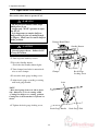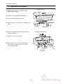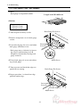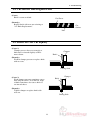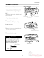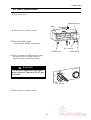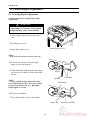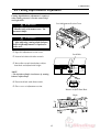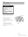
1
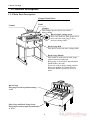
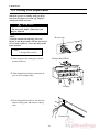
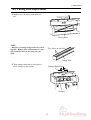
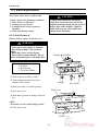
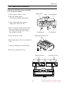
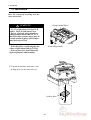
Standard PC-45
Paper Cutter
Instruction Manual
Provided By
http://www.MyBinding.com
http://www.MyBindingBlog.com
PC-45
PAPER CUTTER
Important Information
- This manual is designed to help you to install, operate and maintain Paper Cutter, PC-45.
Read, understand and keep this manual in a safe and convenient place.
- Do not operate PC-45 until you read and understand the instructions in this manual.
- Horizon International Inc. shall not be liable for incidental consequential damages resulting from : improper or inadequate maintenance by customer; unauthorized modification or
misuse; operation outside of the environmental specifications for the product.
- Horizon International Inc. pursues a policy of continuing improvement in design and
performance of the product. Therefore, the product design and specifications are subject to
change without prior notice and without our legal obligation.
- All rights are reserved. No part of the manual may be photocopied, reproduced or translated to another language without the prior written consent of Horizon International Inc.
I
071114/PC45/09E/DV
UM204005-10
Safety Precautions
- The signal word WARNING indicates a potentially hazardous situation which, if not
avoided, could result in death or serious injury.
- The signal word CAUTION indicates a potentially hazardous situation which, if not
avoided, may result in damage on machines. It may also be used to alert against unsafe
practices.
- Read and understand all safety instructions with signal word such as WARNING and
CAUTION. If safety instructions are ignored, personal injury may result.
- Horizon International Inc. cannot anticipate every possible situation that might involve
a potential hazard. The instructions in this manual and warning labels on the machine are
therefore not all inclusive.
- All equipment shall be locked out or tagged out to protect against accidental or inadvertent operation when such operation could cause injury to personnel. Do not attempt to
operate any switch, valve, or other energy isolating device where it is locked or tagged out.
- Do not operate the machines when any covers are removed.
- Some of the drawings in this manual show the machine uncovered for explaining the
detail or inside of machine.
II
CONTENTS
Important Information ............................................................................................ I
Safety Precautions .................................................................................................... II
1. Before You Begin
1-1 Purpose of PC-45 ............................................................................................... 2
1-2 Specifications ...................................................................................................... 2
1-3 Machine Descriptions ........................................................................................ 3
1-3-1 Safety Functions ............................................................................................. 3
1-3-2 Main Parts Descriptions ................................................................................. 4
1-4 Accessories .......................................................................................................... 5
1-5 Consumables ...................................................................................................... 6
2. Safety Function Check
2-1 Check on Table .................................................................................................. 8
2-2 Check on Power ................................................................................................. 8
2-3 Check on Safe Functions ................................................................................... 9
2-3-1 Check on Standby Button ............................................................................... 9
2-3-2 Check on Front Cover .................................................................................... 9
2-3-3 Check on Automatic Return of Knife ............................................................. 10
2-3-4 Check on One Cycle ....................................................................................... 10
2-3-5 Check on Unworkable Knife with One Hand ................................................ 11
2-3-6 Check on Stop during Working ...................................................................... 11
3. Operation Procedure
3-1 Operation Procedure ......................................................................................... 14
4. After Cutting
4-1 Original Condition ............................................................................................. 18
4-2 Power off ............................................................................................................. 18
4-3 Cleaning Table ................................................................................................... 19
III
5. Troubleshooting
5-1 Cut Sheets Are Not Square ............................................................................... 22
5-2 Cut Surface Has Diagonal Lines ...................................................................... 23
5-3 Sheets Are Not Cut Equally .............................................................................. 23
5-4 Sheets Are Not Cut Even After the Power Is Turned On .............................. 24
6. Maintenance
6-1 Cutting Stick Replacement ............................................................................... 26
6-2 Knife Replacement ............................................................................................. 28
6-2-1 Knife Removal ............................................................................................... 28
6-2-2 Knife Installation ............................................................................................ 31
6-3 Knife Height Adjustment .................................................................................. 34
6-3-1 Cutting Depth Adjustment.............................................................................. 34
6-4 Cutting Depth Balance Adjustment ................................................................. 35
6-5 Test Cutting ........................................................................................................ 36
6-6 Lubrication (Monthly) .......................................................................................37
7. Installation
7-1 Installation .......................................................................................................... 40
IV
1. Before You Begin
1. Before You Begin
1-1 Purpose of PC-45 ..................................................................................... 2
1-2 Specifications ........................................................................................... 2
1-3 Machine Descriptions .............................................................................. 3
1-4 Accessories ............................................................................................... 5
1-5 Consumables ............................................................................................ 6
1
1. Before You Begin
1-1 Purpose of PC-45
Horizon PC-45 is a machine for cutting printed sheets, wrapping paper, writing paper, or
booklets.
1-2 Specifications
Model
PC-45
Maximum Cutting Width
446 mm (17.5")
Maximum Lift Height
(Clamp Opening) 70 mm (2.7")
Maximum Cutting Depth
450 mm (17.7")
Minimum Cutting Depth
20 mm (0.8")
Cutting Speed
2.5 sec./cut
Power
120 V 60 Hz 13 A,
220 V 50/60 Hz 4.0 A,
240 V 50 Hz 2.3 A
Power Consumption
1.1 kW
Machine Dimensions (L) x (W) x (H)
790 x 805 x 1,170 mm (31.1" x 31.7" x 46")
Height from the floor level to table top
880 mm (34.6")
Machine Weight
158 kg (348 lb)
The machine design and specifications are subject to change without any notice.
2
1. Before You Begin
1-3 Machine Descriptions
1-3-1 Safety Functions
Front Cover
Standby Button
Key Switch
2
7 8 9
0 1
Cut Button B
Knife works when cut buttons A and B
are pressed at the same time. Knife stops
immediately when either cut button A or
B is released.
Cut Button A
Back Gauge Cover
3
1. Before You Begin
1-3 Machine Descriptions
1-3-2 Main Parts Descriptions
Clamper Hand Wheel
This wheel is used to raise/lower clamper.
Knife
Counter
Clamper
This clamper presses sheets not to move
during cutting.
Back Gauge Locking Screw
This screw locks the back gauge not to
move after the back gauge is fit to
position cutting width.
2
7 8 9
0 1
Back Gauge Dial
This dial is used to measure cutting width.
Back Gauge Handle
This handle is used to move back gauge
either forward or backward.
Back gauge is moved by 5 mm when this
handle makes one turn.
Scales are used to adjust cutting position.
Scales are marked in 0.5 mm intervals.
When this handle is pulled, it is free to
move.
Back Gauge
This gauge is used to position cutting
width.
Side Gauge and Back Gauge Scale
This gauge is used to square-up both sides
of sheets.
4
1. Before You Begin
1-4 Accessories
Spare Knife and Knife Case
1 pc
Spanner 30 mm
Box Wrench
1 pc
Knife Holder
2 pcs
Adjust Bar
1 pc
Tool Box
1 pc
Allen Wrench 3mm, 4 mm, 6mm, 8mm
Ground Wire
1 pc each
1 pc
5
1 pc
1. Before You Begin
1-5 Consumables
Spare Knife C-45
Cutting Stick (M007407-02)
6
2. Safety Function Check
2. Safety Function Check
2-1 Check on Table ........................................................................................ 8
2-2 Check on Power ....................................................................................... 8
2-3 Check on Safe Functions ......................................................................... 9
7
2. Safety Function Check
2-1 Check on Table
Table must be clean.
1. Check that trimmings, adhesive, or grease
is not on table.
NOTE
- Clean table referring to "4-3 Cleaning
table" if table is dirt.
6
1 2 3
4 5
Table
2-2 Check on Power
Check that power turns on.
Key Switch
1. Insert key into power switch and turn key
clockwise to switch on power.
CUTT
- Power pilot lamp will illuminate.
POW
ER B
ER
ON
OFF
Power Pilot Lamp
8
6
1 2 3
4 5
2. Safety Function Check
2-3 Check on Safe Functions
WARNING
- Do not put your hands under knife
while power is on.
- Assign only "ONE" operator to operate PC-45.
If your PC-45 do not work as shown in this
book, ask your local dealer to fix the PC-45.
2-3-1 Check on Standby Button
Clamper Hand Wheel
Check that knife work only when Standby
button is pressed.
Front Cover
Standby Button
Check that the lamp on Standby button is
turned off.
1. Lower clamper to the bottom with clamper
hand wheel.
2. Check that knife does not work in spite of
pressing cut buttons A and B at the same
time.
6
1 2 3
4 5
3. Press the Standby button.
- Check that the Standby button lights.
Cut Button A
2-3-2 Check on Front Cover
Check that knife do not work while front
cover is open.
1. Lower clamper to the bottom with clamper
hand wheel.
2. Open front cover.
3. Check that knife does not work in spite of
pressing cut buttons A and B at the same
time.
4. Close front cover.
9
Cut Button B
2. Safety Function Check
2-3 Check on Safe Functions
2-3-3 Check on Automatic Return of Knife
Check that knife at bottom position returns to
home position automatically and then stops.
Knife
1. Press cut buttons A and B at the same
time.
2. Release your hands from cut buttons when
knife is on the way to home position.
- Check that knife returns to home position
without stopping and then stops at home
position.
Cut Button A
2-3-4 Check on One Cycle
Check that knife remains stationary if cut
buttons are continued to press after knife
returns to home position.
1. Continue pressing to cut buttons about 5
seconds after knife returns to home position. Check that knife does not work
again.
Next, check that knife remains stationary
unless both hands are released from cut
buttons.
2. Release your hand from cut button B with
cut button A pressed.
3. Press cut button B again. Check that knife
does not work.
10
6
1 2 3
4 5
Cut Button B
2. Safety Function Check
2-3 Check on Safe Functions
2-3-5 Check on Unworkable Knife with One Hand
Check that knife work only when both cut
buttons A and B are pressed at the same time.
Knife
1. Check that knife does not work by pressing only cut button A.
2. Check that knife does not work by pressing cut button B with cut button A pressed.
NOTE
- Knife works only when both cut buttons A
and B are pressed at the same time (within 5
seconds).
6
1 2 3
4 5
3. Release your hands from cut buttons.
Cut Button A
4. Check that knife does not work by repeat-
Cut Button B
ing procedure 1 to 3, exchanging A with B.
2-3-6 Check on Stop during Working
WARNING
- Do not raise clamper when knife is
stopped during cutting. Otherwise
knife gets bare and, as a result, your
fingers might be cut with knife.
NOTE
- Knife can return to home position by pressing cut button A and B separately with the
interval of 0.5 seconds or more when knife is
stopped on the way to bottom.
4. Repeat procedure 1, exchanging A with B.
Knife
Check that knife is stopped when you release
your hand from even one cut button during
lowering knife.
1. Check that knife is stopped immediately
when you release your hand from cut
button A while knife is lowering after you
press cut button A and B at the same time.
2. Release your hands from cut buttons.
6
1 2 3
4 5
3. Press cut button A and B separately with
the interval of 0.5 seconds or more to
return the knife to the home position.
Cut Button A
11
Cut Button B
2. Safety Function Check
12
3. Operation Procedure
3. Operation Procedure
3-1 Operation Procedure ............................................................................... 14
13
3. Operation Procedure
3-1 Operation Procedure
This section shows how to operate PC-45.
WARNING
- Do not put your hands under knife
while power is on.
- Assign only "ONE" operator to operate PC-45.
- It is dangerous to remain knife on
half position for fear of cutting hands
or fingers. Make sure to return knife to
home position.
Clamper Hand Wheel
Standby Button
CAUTION
- Cut only paper sheets. Otherwise PC45 may be broken.
1. Turn on power with key switch.
4 5
1 2 3
6
2. Press the Standby button.
- Check that the Standby button lights.
Key Switch
3. Turn clamper hand wheel counterclock-
Clamper
wise to raise clamper.
Back Gauge
Locking Screw
4. Loosen the back gauge locking screw.
5. Adjust back gauge according to cutting
with back gauge handle.
Scale
NOTE
- Move back gauge from rear side to front
side. Otherwise, it errs in cutting width.
- Cutting line helps to see cutting position.
Cutting line is the beam that is reflected on
sheets.
2
7 8 9
0 1
6. Tighten the back gauge locking screw.
Back Gauge Handle
14
Back Gauge Dial
3. Operation Procedure
3-1 Operation Procedure
Sheets
7. Open front cover and pile sheets on table.
8. Square-up sheets with back gauge and side
gauge.
Back Gauge
Side Gauge
Clamper Hand Wheel
9. Turn clamper hand wheel, and clamper
will press sheets to fix them.
NOTE
- Be careful not to shift sheets when fixing
sheets.
10. Close front cover.
6
1 2 3
4 5
11. Continue to press cut button A and B at
the same time, and knife lowers and cuts
sheets. You may release cut buttons when
knife begins to rise because knife returns to
home position automatically.
Clamper
Front Cover
NOTE
- If you fail to press both cut buttons at the
same time, release your hands from buttons
and try it again 2 seconds later.
- If you release your hand(s) from cut
button(s) while knife is lowering and cutting
operation is stopped, press cut button A and
B separately with the interval of 0.5 seconds
or more, and knife returns to home position.
Knife
Cut Button A
15
6
1 2 3
4 5
Cut Button B
3. Operation Procedure
3-1 Operation Procedure
Front Cover
12. Make sure knife has returned to home
position after cutting.
13. Release your hands from cut buttons.
14. Turn off power with key switch.
15. Open front cover and remove trimmings on
table.
Trimmings
Clamper Hand Wheel
16. Loosen clamper hand wheel by turning it
counterclockwise.
17. Take cut sheets out of table.
18. Repeat procedure 1 to 14. Back gauge is
not required to adjust in the case of the
same cutting width.
6
1 2 3
4 5
Cut Sheets
16
6
1 2 3
4 5
4. After Cutting
4. After Cutting
4-1 Original Condition .................................................................................. 18
4-2 Power off ................................................................................................... 18
4-3 Cleaning Table ......................................................................................... 19
17
4. After Cutting
4-1 Original Condition
Clamper must be lowered to the bottom after
finishing operation.
1. Lower clamper to the bottom by turning
Clamper Hand Wheel
clamper hand wheel clockwise.
2. If knife remains on half way, press cut
button A and B separately with the interval
of 0.5 seconds or more to return the knife
to the home position.
6
1 2 3
4 5
Clamper
Cut Button A
Cut Button B
4-2 Power off
Power is turned off.
Key
WARNING
CUTT
POW
- Only authorized operators should
have access to key switch.
ER B
ER
ON
OFF
1. Turn off power by turning key switch
counterclockwise.
- When turning on the power again, turning
it on after the Standby button completely
goes out.
Key Switch
Standby Button
2. Pull out key and keep it.
18
6
1 2 3
4 5
4. After Cutting
4-3 Cleaning Table
Clean table after operating PC-45.
1. Make sure power is off.
Key Switch
CUTT
POW
ER B
ER
ON
OFF
2. Lower clamper to the bottom by turning
Clamper Hand Wheel
clamper hand wheel clockwise.
3. Wipe trimmings off table with soft cloth.
Clamper
19
6
1 2 3
4 5
Table
4. After Cutting
20
5. Troubleshooting
5. Troubleshooting
5-1 Cut Sheets Are Not Square ..................................................................... 22
5-2 Cut Surface Has Diagonal Lines ............................................................ 23
5-3 Sheets Are Not Cut Equally.................................................................... 23
5-4 Sheets Are Not Cut Even After the Power Is Turned On ................... 24
21
5. Troubleshooting
5-1 Cut Sheets Are Not Square
(Cause)
Back gauge is not parallel to knife.
Length A and B is different.
B
(Remedy)
A
Tools:
1. Wrench 5 mm
2. Wrench 4 mm
Back Gauge Fix Screws
1. Turn off power with key switch.
2. Remove transparent cover in back gauge
section.
3. Loosen back gauge fix screws and adjust
back gauge with adjust screw.
Fasten
Screw B
Loosen Screw A
- Back gauge moves clockwise by loosening screw A and fastening screw B.
Length B is shortened by moving back
gauge clockwise.
Adjust Screw
4. Fasten back gauge fix screw after adjusting of back gauge.
5. Turn on power and check that edges are
Back Gauge Fix Screws
parallel by test cutting.
6. Repeat procedure 1 to 4 until one edge
parallels another edge.
Loosen
Screw B
Fasten Screw A
Adjust Screw
22
5. Troubleshooting
5-2 Cut Surface Has Diagonal Lines
(Cause)
Knife is worn or nicked.
Cut Sheets
(Remedy)
Replace knife with new one referring to
"6-2 Knife Replacement".
Cut
Surface
Line
5-3 Sheets Are Not Cut Equally
(Cause 1)
Clamper presses sheets too strongly or
knife moves forward slightly as knife
moves down.
Clamper
Knife
(Remedy)
Weaken clamper pressure or replace knife
with new one.
Cutting Stick
Clamper
(Cause 2)
Weak clamper pressure sometimes causes
bow-shaped section. Less than 20˚ angle
of knife sometimes also causes knife to
cut inward sheets.
Knife
(Remedy)
Tighten clamper or replace knife with
new one.
Cutting Stick
23
5. Troubleshooting
5-4 Sheets Are Not Cut Even After the Power Is Turned On
(Cause)
The Standby button is not pressed.
Standby Button
(Remedy)
Press the Standby button.
24
6
1 2 3
4 5
6. Maintenance
6. Maintenance
6-1 Cutting Stick Replacement ..................................................................... 26
6-2 Knife Replacement .................................................................................. 28
6-3 Knife Height Adjustment ........................................................................ 34
6-4 Cutting Depth Balance Adjustment ...................................................... 35
6-5 Test Cutting .............................................................................................. 36
6-6 Lubrication (Monthly) ............................................................................ 37
25
6. Maintenance
6-1 Cutting Stick Replacement
When the groove on cutting stick gets deep,
last sheet is left uncut or torn off. Replace
cutting stick with new one.
WARNING
- Do not touch knife. Otherwise you
may be injured.
NOTE
- If knife remains on half way, press cut
button A and B separately with the interval of
0.5 seconds or more to return the knife to the
home position.
Key Switch
CUTT
POW
ER
ON
OFF
Tool:
1. Straight Screwdriver
1. Turn off power by turning key switch
Clamper Hand Wheel
counterclockwise.
2. Turn clamper hand wheel counterclockwise to raise clamper fully.
Clamper
3. Insert Straight Screwdriver into the bottom of cutting stick and remove cutting
stick.
Cutting Stick
26
6
1 2 3
4 5
ER B
6. Maintenance
6-1 Cutting Stick Replacement
4. Replace face of cutting stick with new
one.
Cutting Stick
NOTE
- One face of cutting stick provides two working line. Replace face with another new face
after both two lines on the same face are
used.
Two Lines on One Face
Cutting Stick
5. Turn clamper hand wheel clockwise to
Clamper Hand Wheel
lower clamper to the bottom.
Clamper
27
6
1 2 3
4 5
6. Maintenance
6-2 Knife Replacement
This section shows how to replace knife.
CAUTION
- Replace knife in the following conditions;
1. Some sheets are left uncut.
2. Cutting noise gets louder.
3. Trimmed sheets are not separated
smoothly.
4. Knife stops during cutting.
- When some sheets are left uncut,
knife does not need to be replaced by
adjusting cutting depth, but use of worn
knife cause some troubles. Replace
knife with new one when knife cuts
sheets about 500 times.
6-2-1 Knife Removal
Remove knife to replace it with new one.
WARNING
- Wear gloves when knife is replaced.
- Be careful of knife. Do not touch
knife.
- Knife may cause serious injury.
- Be careful of removed knife. Do not
put it on unstable place with knife bare.
Clamper Hand Wheel
Tools;
1. Felt Pen
2. Box Wrench
3. Two Knife Holder
6
1 2 3
4 5
1. Turn off power with key switch.
2. Turn clamper hand wheel to lower
Clamper
clamper to the bottom.
3. Make sure knife is on home position.
Front Cover
4. Open front cover.
5. Mark knife position on clamper with felt
pen.
NOTE
- This mark is used to adjust knife position.
6. Close front cover.
Felt Pen
28
Key Switch
6. Maintenance
6-2 Knife Replacement
Knife Securing Bolts
7. Turn on power with key switch.
8. Press cut buttons A and B to lower knife
until all four knife securing bolts appear.
6
1 2 3
4 5
NOTE
- Do not lower knife too low. Otherwise knife
cannot be removed.
Cut Button A
Key Switch
9. Turn off power with key switch.
Cut Button A
10. Press the Standby button.
Standby Button
- Check that the Standby button lights.
11. Open front cover.
12. Remove the center two of four knife securing bolts with box wrench.
Knife Securing Bolts
13. Fasten knife holders enough.
WARNING
- Fastening knife holder insufficiently
may cause knife to fall and severe
injury to operators as a result. Do
fasten knife holder completely as
shown in the drawing below.
Knife Holder
Knife Holder
Knife
29
6
3
4 5
6. Maintenance
6-2 Knife Replacement
14. Loosen the rest of two knife securing bolts
with box wrench.
15 Remove knife securing bolts with box
wrench turning knife holder clockwise not
to fall knife.
6
1 2 3
4 5
16. Slide knife to the left and remove it slowly.
Knife Securing Bolts
WARNING
- Knife may cause serious injury if you
touch it lightly. Take care knife is not
touched by other persons or falls.
Knife Holder
17. Put knife on safe place, remove knife
holder, put knife in knife case, and request
to sharpen knife to your local dealer or
knife resharping shop.
Knife Holder
Knife Case
30
6
2 3
4 5
6. Maintenance
6-2 Knife Replacement
6-2-2 Knife Installation
This section shows how to install knife.
WARNING
- Wear gloves when knife is replaced.
- Be careful of knife. Do not touch
knife directly.
- Knife may cause serious injury.
- Be careful of removed knife. Do not
put it on unstable place with knife bare.
NOTE
Sharpening Specifications
- Knife must be grounded to an angle of 20˚.
- Grind knife as little an necessary.
- Sharpened knife must have at least 65 mm
height. Replace knife whose height is less
than 65 mm with new one.
1. Turn off power with key switch.
Key Switch
CUTT
POW
ER
ON
OFF
2. Make sure all four knife securing holes
can be seen.
6
2 3
4 5
Knife Securing holes
31
ER B
6. Maintenance
6-2 Knife Replacement
Knife Holders
3. Fasten two knife holders in center two
holes in the right drawing.
NOTE
- Be careful not to mistake the right side of
knife.
The Right Side of
Knife
WARNING
- Fastening knife holder insufficiently
may cause knife to fall and severe
injury to operators as a result. Do put
screw section of knife holder completely as shown in the drawing below.
Knife Holder
Knife
6
1 2 3
4 5
Knife
Knife Holders
4. Open front cover.
Knife Holders
5. Raise knife holders fitting knife securing
groove and slide knife holders to the right.
6. Fasten knife securing bolts with box
wrench, lifting knife with knife holder.
6
2 3
4 5
Knife Securing Bolts
7. Remove knife holder and fasten two knife
securing bolts there with box wrench.
Knife Securing Bolts
32
6. Maintenance
6-2 Knife Replacement
8. Close front cover.
Standby Button
Knife
9. Turn on power with key switch.
4 5
1 2 3
6
10. Press the Standby button.
- Check that the Standby button lights.
Key Switch
Cut Button B
Cut Button A
11. Press cut button A and B separately with
the interval of 0.5 seconds or more to
return the knife to the home position.
WARNING
CUTT
- Do not lower knife until knife adjustment is finished. Otherwise PC-45 may
be broken.
POW
ER
ON
OFF
Key Switch
12. Turn off power with key switch.
33
ER B
6. Maintenance
6-3 Knife Height Adjustment
6-3-1 Cutting Depth Adjustment
Cutting depth must be adjusted after knife
replacement.
WARNING
- Operating PC-45 before cutting depth
is adjusted may cause some troubles.
1. Turn clamper hand wheel to lower pressure.
2. Unplug power cord.
Knife Adjust Cover
3. Open knife adjust cover.
NOTE
- Turn lock nut clockwise to loose lock nut.
4. Loosen two lock nuts of knife height
adjust screws with spanner.
Loosen
5. Turn turnbuckle with adjust bar into adjust
Fasten
screws hole to fit knife with the mark with
felt pen.
Spanner
NOTE
- 1/6 turn of knife height adjust bolts raise/
lower knife about 0.6 mm. Excessive cutting
pressure does harm to PC-45. Maximum
cutting depth is 0.5 mm.
Lock Nuts
Turnbuckle
Lower
6. Fasten two locknuts.
Raise
7. Close knife adjust cover on the bottom.
Adjust Bar
34
Adjust Screw Hole
6. Maintenance
6-4 Cutting Depth Balance Adjustment
Cutting depth balance adjustment is required
when cutting pressure is not the same in left
and right sides.
Left Adjustment Section Cover
WARNING
- Handle knife with utmost care. Do
not touch knife.
CAUTION
- After adjusting cutting depth balance,
knife height adjustment is required in
some case.
1. Open left adjustment section cover.
Lock Bolt
2. Loosen lock bolt with allen wrench.
3. Insert allen wrench into balance adjust
shaft hole and adjust knife height.
NOTE
- The left side of knife rises/lowers by turning
balance adjust shaft.
Down
Up
4. Fasten lock bolt with allen wrench.
5. Close cover of adjustment section.
Balance Adjust Shaft Hole
Knife
Up
Down
35
6
1 2 3
4 5
6. Maintenance
6-5 Test Cutting
Check on knife cutting condition.
WARNING
- Do not put your hands and fingers
under knife. Otherwise you may be
injured seriously.
- Do not put your hands under knife
while power is on.
- Assign only "ONE" operator to operate PC-45.
- It is dangerous to remain knife on
half position for fear of cutting hands
or fingers. Make sure to return knife
to home position.
1. Place sheets on both edge of table one by
Standby Button
one.
2. Turn power on with key switch.
3. Press the Standby button.
- Check that the Standby button lights.
4. Operate PC-45 referring to "3-1 Operation
Procedure".
5. If both sheets are left uncut partially,
Sheets
adjust knife height again. (Page 32)
6. If either paper is left uncut partially, adjust
knife height.
36
6
1 2 3
4 5
6. Maintenance
6-6 Lubrication (Monthly)
Lubricate the following sections to maintain
PC-45 in the best condition.
Cutting Stick
1. Turn on power with key switch.
Knife
Standby Button
2. Press the Standby button.
- Check that the Standby button lights.
3. Turn clamper hand wheel to lower
5mm
clamper to the surface of table.
4. Press cut buttons A and B to lower knife.
Release cut buttons when clearance between knife and cutting stick is about 5
mm, and knife will stop.
Cut Button A
6
1 2 3
4 5
Cut Button B
Adjustemt Section Covers
5. Turn off with key switch.
6. Open adjustment section covers (right and
left).
7. Lubricate sliding faces between marks.
8. Close tops of lubricate section.
Lubricate Section
37
Lubricate Section
6. Maintenance
6-6 Lubrication (Monthly)
9. Open knife adjust cover and apply grease
on driving and rotating section. (Arrow
marks)
Knife Adjust Cover
10. Close knife adjust cover.
11. Turn on power with key switch.
12. Press cut button A and B separately with
the interval of 0.5 seconds or more to
return the knife to the home position.
38
7. Installation
7. Installation
7-1 Installation ............................................................................................... 40
39
7. Installation
7-1 Installation
Place PC-45 properly according to its machine dimensions.
Clamper Hand Wheel
WARNING
- PC-45 weighs about 160 kg/332 lb
totally. Move it with utmost care.
- Do not grip back gauge handle or
clamper hand wheel when PC-45 is
moved because serious injury may be
caused and back gauge and clamper
may lack in precision.
CAUTION
- Select flat floor considering the machine weight (about 160 kg/332 lb).
- Select a place free from extremely
high temperature and humidity.
Back Gauge Handle
1. Unpack the machine and remove four
locking plates (at the front and rear).
Locking Plate
40
2
7 8 9
0 1
7. Installation
7-1 Installation
Assembling the pedestal for PC-45.
2. Insert one end of the prop (3 pcs) into the
large holes at the right leg and fix the
props with the spring washers and the
hexagon head bolts with using of the
supplied box wrench.
Top Panel
Top Lid
3. Put the back panel on the props and
secure them to the left leg.
Large Hole
Hook
Back
4. Place the both semi-assembled legs on the
flat floor and secure firmly the hexagon
head bolts at the left leg.
Hexagon
5. Fit a top lid on the top panel and mount it
Props
on the leg assembly as shown in the right
drawing.
Right
Front
6. Mount the PC-45 machine on the top
panel so that the hooks on the right leg are
fitted in the bottom notches of the PC-45
machine.
Legs
Props
Spring WashLeft Leg
2 Top Panel 1 Hexagon
6
3 Top Lid 1 Bolts
Back Panel 1
Washers 6
41
7. Installation
7-1 Installation
7. Place PC-45 on the stand in correct direction.
Clamper Hand Wheel
NOTE
- Make sure PC-45 is not placed on hook.
0 1
7 8 9
2
8. Install clamper hand wheel.
9. Install back gauge handle.
Back Gauge Handle
10. Connect ground wire. (Contact electrical
appliance store.)
Ground Terminal
11. Plug power plug into outlet.
Power Plug
42