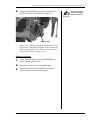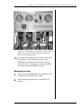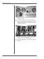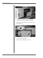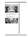
1
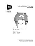
Goliath Guillotine Pipe Saw
User’s Manual
E.H. Wachs Company
600 Knightsbridge Parkway
Lincolnshire, IL 60069
www.wachsco.com
E.H. Wachs Company Part No. 06-150-520-MAN
Rev. 0-0607, June 2007
Revision History:
Version 1
June 2007
Copyright © 2007 E.H. Wachs Company. All rights reserved.
This manual may not be reproduced in whole or in part
without the written consent of E.H. Wachs Company.
Goliath Guillotine Pipe Saw
Part No. 06-150-520-MAN, Rev. 0-0607
E.H. Wachs Company
Table of Contents
Chapter 1: About This Manual . . . . . . . . . . . . . . . . . . . . . . . . . . . . . . . . . . . . . . . . . 1
Purpose of This Manual . . . . . . . . . . . . . . . . . . . . . . . . . . . . . . . . . . . . . . . . . . . . . . . . . . . . . . .1
How to Use The Manual . . . . . . . . . . . . . . . . . . . . . . . . . . . . . . . . . . . . . . . . . . . . . . . . . . . . . . .2
Symbols and Warnings. . . . . . . . . . . . . . . . . . . . . . . . . . . . . . . . . . . . . . . . . . . . . . . . . . . . . . . .2
Manual Updates and Revision Tracking . . . . . . . . . . . . . . . . . . . . . . . . . . . . . . . . . . . . . . . . .3
Chapter 2: Safety . . . . . . . . . . . . . . . . . . . . . . . . . . . . . . . . . . . . . . . . . . . . . . . . . . . . 5
Operator Safety. . . . . . . . . . . . . . . . . . . . . . . . . . . . . . . . . . . . . . . . . . . . . . . . . . . . . . . . . . . . . .5
Safety Symbols . . . . . . . . . . . . . . . . . . . . . . . . . . . . . . . . . . . . . . . . . . . . . . . . . . . . . . . . . .6
Safety Labels . . . . . . . . . . . . . . . . . . . . . . . . . . . . . . . . . . . . . . . . . . . . . . . . . . . . . . . . . . . . . . . .7
Machine Safety . . . . . . . . . . . . . . . . . . . . . . . . . . . . . . . . . . . . . . . . . . . . . . . . . . . . . . . . . . . . . .7
Chapter 3: Introduction to the Goliath Guillotine . . . . . . . . . . . . . . . . . . . . . . . . . . 9
Usage and Applications . . . . . . . . . . . . . . . . . . . . . . . . . . . . . . . . . . . . . . . . . . . . . . . . . . . . . . .9
Machine Control . . . . . . . . . . . . . . . . . . . . . . . . . . . . . . . . . . . . . . . . . . . . . . . . . . . . . . . . . . . .11
Specifications . . . . . . . . . . . . . . . . . . . . . . . . . . . . . . . . . . . . . . . . . . . . . . . . . . . . . . . . . . . . . . .13
Operating Envelope . . . . . . . . . . . . . . . . . . . . . . . . . . . . . . . . . . . . . . . . . . . . . . . . . . . . . . . . .13
Accessories . . . . . . . . . . . . . . . . . . . . . . . . . . . . . . . . . . . . . . . . . . . . . . . . . . . . . . . . . . . . . . . . .15
Chapter 4: Assembly, Disassembly, and Storage. . . . . . . . . . . . . . . . . . . . . . . . . 17
Environmental Requirements . . . . . . . . . . . . . . . . . . . . . . . . . . . . . . . . . . . . . . . . . . . . . . . . .17
Long-Term Storage. . . . . . . . . . . . . . . . . . . . . . . . . . . . . . . . . . . . . . . . . . . . . . . . . . . . . . . . . .17
Chapter 5: Operating Instructions . . . . . . . . . . . . . . . . . . . . . . . . . . . . . . . . . . . . . 19
Lifting the Saw . . . . . . . . . . . . . . . . . . . . . . . . . . . . . . . . . . . . . . . . . . . . . . . . . . . . . . . . . . . . .19
Installing the Blade . . . . . . . . . . . . . . . . . . . . . . . . . . . . . . . . . . . . . . . . . . . . . . . . . . . . . . . . . .23
Using the Autofeed . . . . . . . . . . . . . . . . . . . . . . . . . . . . . . . . . . . . . . . . . . . . . . . . . . . . . . . . . .27
Mechanical Autofeed . . . . . . . . . . . . . . . . . . . . . . . . . . . . . . . . . . . . . . . . . . . . . . . . . . . . .27
Hydraulic Autofeed . . . . . . . . . . . . . . . . . . . . . . . . . . . . . . . . . . . . . . . . . . . . . . . . . . . . . .30
Operating the Standard Machine . . . . . . . . . . . . . . . . . . . . . . . . . . . . . . . . . . . . . . . . . . . . . .31
Connecting the Hoses . . . . . . . . . . . . . . . . . . . . . . . . . . . . . . . . . . . . . . . . . . . . . . . . . . . .31
Clamping the Saw to the Workpiece . . . . . . . . . . . . . . . . . . . . . . . . . . . . . . . . . . . . . . . . .32
Operating the Saw . . . . . . . . . . . . . . . . . . . . . . . . . . . . . . . . . . . . . . . . . . . . . . . . . . . . . . .35
Removing the Saw . . . . . . . . . . . . . . . . . . . . . . . . . . . . . . . . . . . . . . . . . . . . . . . . . . . . . . .37
Operating the Machine with the Topside Control Unit . . . . . . . . . . . . . . . . . . . . . . . . . . . .38
Connecting the Hoses . . . . . . . . . . . . . . . . . . . . . . . . . . . . . . . . . . . . . . . . . . . . . . . . . . . .38
Connecting Hoses to the TCU . . . . . . . . . . . . . . . . . . . . . . . . . . . . . . . . . . . . . . . . . . .38
Connecting Hoses to the Goliath . . . . . . . . . . . . . . . . . . . . . . . . . . . . . . . . . . . . . . . . .40
Clamping the Saw to the Workpiece . . . . . . . . . . . . . . . . . . . . . . . . . . . . . . . . . . . . . . . . .42
Operating the Saw . . . . . . . . . . . . . . . . . . . . . . . . . . . . . . . . . . . . . . . . . . . . . . . . . . . . . . .44
Mechanical Autofeed . . . . . . . . . . . . . . . . . . . . . . . . . . . . . . . . . . . . . . . . . . . . . . . . . .45
Hydraulic Autofeed . . . . . . . . . . . . . . . . . . . . . . . . . . . . . . . . . . . . . . . . . . . . . . . . . . .47
Removing the Saw . . . . . . . . . . . . . . . . . . . . . . . . . . . . . . . . . . . . . . . . . . . . . . . . . . . . . . .51
Goliath Guillotine Pipe Saw
Chapter 6: Routine Maintenance . . . . . . . . . . . . . . . . . . . . . . . . . . . . . . . . . . . . . . 55
Grease Points. . . . . . . . . . . . . . . . . . . . . . . . . . . . . . . . . . . . . . . . . . . . . . . . . . . . . . . . . . . . . . .55
Autoclamp Lubrication . . . . . . . . . . . . . . . . . . . . . . . . . . . . . . . . . . . . . . . . . . . . . . . . . . .59
Chapter 7: Service and Repair . . . . . . . . . . . . . . . . . . . . . . . . . . . . . . . . . . . . . . . . 61
Troubleshooting . . . . . . . . . . . . . . . . . . . . . . . . . . . . . . . . . . . . . . . . . . . . . . . . . . . . . . . . . . . .61
Chapter 8: Parts List and Ordering Information . . . . . . . . . . . . . . . . . . . . . . . . . . 63
Parts List . . . . . . . . . . . . . . . . . . . . . . . . . . . . . . . . . . . . . . . . . . . . . . . . . . . . . . . . . . . . . . . . . .63
Autofeed Drawing. . . . . . . . . . . . . . . . . . . . . . . . . . . . . . . . . . . . . . . . . . . . . . . . . . . . . . . . . . .69
Ordering Information . . . . . . . . . . . . . . . . . . . . . . . . . . . . . . . . . . . . . . . . . . . . . . . . . . . . . . .71
Ordering Replacement Parts . . . . . . . . . . . . . . . . . . . . . . . . . . . . . . . . . . . . . . . . . . . . . . .71
Repair Information . . . . . . . . . . . . . . . . . . . . . . . . . . . . . . . . . . . . . . . . . . . . . . . . . . . . . .71
Warranty Information . . . . . . . . . . . . . . . . . . . . . . . . . . . . . . . . . . . . . . . . . . . . . . . . . . . .71
Return Goods Address. . . . . . . . . . . . . . . . . . . . . . . . . . . . . . . . . . . . . . . . . . . . . . . . . . . .71
Part No. 06-150-520-MAN, Rev. 0-0607
E.H. Wachs Company
Chapter 1, About This Manual
Chapter 1
About This Manual
In This Chapter
PURPOSE OF THIS MANUAL
This manual explains how to operate and maintain the Goliath Guillotine pipe saw. It includes instructions for set-up,
operation, and maintenance. It also contains parts lists and
diagrams, and troubleshooting instructions to help you
order replacement parts and perform user-serviceable
repairs.
PURPOSE OF THIS MANUAL
HOW TO USE THE MANUAL
SYMBOLS AND WARNINGS
MANUAL UPDATES AND
REVISION TRACKING
Before operating the Goliath, you should read through this
manual and become familiar with all instructions. At a minimum, make sure you read and understand the following
chapters:
•
•
•
•
•
Chapter 1, About This Manual
Chapter 2, Safety
Chapter 3, Introduction to the Goliath Guillotine
Chapter 5, Operating Instructions
Chapter 9, Accessories
If you will be performing service or repairs, make sure you
read and understand these chapters:
•
•
•
•
Chapter 1, About This Manual
Chapter 4, Assembly and Disassembly
Chapter 6, Routine Maintenance
Chapter 7, Troubleshooting and Repair.
E.H. Wachs Company
Part No. 06-150-520-MAN, Rev. 0-0607
1
Goliath Guillotine Pipe Saw
You will also want to refer to Chapter 8, Parts Lists and
Drawings.
HOW TO USE THE MANUAL
Throughout this manual, refer
to this column for warnings,
cautions, and notices with
supplementary information.
This manual is organized to help you quickly find the information you need. Each chapter describes a specific topic on
using or maintaining the equipment.
Each page is designed with two columns. This large column
on the inside of the page contains instructions and illustrations. Use these instructions to operate and maintain the
equipment.
The narrower column on the outside contains additional
information such as warnings, special notes, and definitions.
Refer to it for safety notes and other information.
SYMBOLS AND WARNINGS
The following symbols are used throughout this manual to
indicate special alerts and notes. They appear in the outside
column of the page, next to the section they refer to. Make
sure you understand what each symbol means, and follow
all instructions for cautions and warnings.
This is the safety alert symbol. It is used
to alert you to potential personal injury
hazards. Obey all safety messages that
follow this symbol to avoid possible
injury or death.
NOTE
This symbol indicates a user notice.
Notices provide additional information to
supplement the instructions, or tips for
easier operation.
2
Part No. 06-150-520-MAN, Rev. 0-0607
E.H. Wachs Company
Chapter 1, About This Manual: Manual Updates and Revision Tracking
MANUAL UPDATES AND REVISION TRACKING
Occasionally, we will update manuals with improved operation or maintenance procedures, or with corrections if necessary. Revised chapters will be available for customers. If
you receive revised chapters for your manual, remove the
old chapters from your binder and replace them with the
new chapters.
Current versions of E.H.
Wachs Company manuals
are also available in PDF format. You can request an
electronic copy of this manual
by emailing customer service
at [email protected].
When a manual is revised, we will update the revision history on the title page and at the bottom of the pages in the
revised chapters. It is important to put the current title page
with the revision history in your manual. This will help you
make sure you have all current information.
You may have factory service or upgrades performed on the
equipment. If this service changes any technical data or
operation and maintenance procedures, we will include
revised sections of the manual when we return the equipment to you. Remove the old chapters from your manual
and replace them with the revised chapters.
E.H. Wachs Company
Part No. 06-150-520-MAN, Rev. 0-0607
3
Goliath Guillotine Pipe Saw
4
Part No. 06-150-520-MAN, Rev. 0-0607
E.H. Wachs Company
Chapter 2, Safety
Chapter 2
Safety
The E.H. Wachs Company takes great pride in designing
and manufacturing safe, high-quality products. We make
user safety a top priority in the design of all our products.
In This Chapter
OPERATOR SAFETY
SAFETY LABELS
WARNING
MACHINE SAFETY
Read this chapter carefully before operating your Goliath
Guillotine pipe saw. Serious injury or death could result
from improper operation or repair of this equipment.
Repair and/or service to this equipment must only be done
by an authorized and certified dealer.
OPERATOR SAFETY
Follow these guidelines for safe operation of the equipment.
•
•
•
READ THE OPERATING MANUAL. Make sure you
understand all setup and operating instructions before
you begin.
INSPECT MACHINE AND ACCESSORIES. Before
starting the machine, look for loose bolts or nuts, leaking lubricant, rusted components, and any other physical
conditions that may affect operation. Properly maintaining the machine can greatly decrease the chances for
injury.
ALWAYS READ PLACARDS AND LABELS. Make
sure all placards, labels, and stickers are clearly legible
E.H. Wachs Company
Part No. 06-150-520-MAN, Rev. 0-0607
Look for this symbol throughout the
manual. It indicates
a personal injury
hazard.
5
Goliath Guillotine Pipe Saw
•
•
•
and in good condition. You can purchase replacement
labels from E.H. Wachs Company.
KEEP CLEAR OF MOVING PARTS. Keep hands,
arms, and fingers clear of all rotating or moving parts.
Always turn machine off before doing any adjustments
or service.
SECURE LOOSE CLOTHING AND JEWELRY.
Secure or remove loose-fitting clothing and jewelry, and
securely bind long hair, to prevent them from getting
caught in moving parts of the machine.
KEEP WORK AREA CLEAR. Keep all clutter and
nonessential materials out of the work area. Only people
directly involved with the work being performed should
have access to the area.
Safety Symbols
This icon is displayed with any safety alert that indicates a
personal injury hazard.
WARNING
This safety alert indicates a potentially hazardous situation
that, if not avoided, could result in death or serious injury.
CAUTION
This safety alert, with the personal injury hazard symbol,
indicates a potentially hazardous situation that, if not
avoided, could result in minor or moderate injury.
NOTICE
This alert indicates a situation that, if not avoided, will
result in damage to the equipment.
IMPORTANT
This alert indicates a situation that, if not avoided, may
result in damage to the equipment.
6
Part No. 06-150-520-MAN, Rev. 0-0607
E.H. Wachs Company
Chapter 2, Safety: Safety Labels
SAFETY LABELS
There are two safety labels on the Goliath Guillotine saw.
These are illustrated in Figure 2-1 and Figure 2-2.
Figure 2-1. Observe the warning label for moving
parts hazards.
Figure 2-2. Observe the warning label for blade hazard.
MACHINE SAFETY
Observe the following guidelines for reliable machine operation and care.
•
•
Make sure all hydraulic couplers are wiped clean before
connection.
Make sure all pressure and return hoses are connected to
the correct couplings.
E.H. Wachs Company
Part No. 06-150-520-MAN, Rev. 0-0607
NOTICE
Failure to follow the instructions for machine safety
could result in damage to the
equipment.
7
Goliath Guillotine Pipe Saw
•
•
•
•
•
•
•
8
Always replace blades, hydraulic components, and other
parts with replacement parts recommended by the E.H.
Wachs Company.
Keep the machine lubricated according to the instructions in Chapter 6.
Make sure the blade is tight before cutting.
Do not exceed the rated hydraulic flow (see Specifications in Chapter 3).
Always keep critical tool markings, such as warning
stickers and tags, legible.
Do not use the saw for applications for which it is not
intended.
Service and repair should be performed by experienced
personnel only.
Part No. 06-150-520-MAN, Rev. 0-0607
E.H. Wachs Company
Chapter 3, Introduction to the Goliath
Chapter 3
Introduction to the
Goliath Guillotine
Read this chapter carefully to become familiar with the
components and features of your Goliath Guillotine pipe
saw.
In This Chapter
USAGE AND APPLICATIONS
MACHINE CONTROL
SPECIFICATIONS
USAGE AND APPLICATIONS
The Goliath Guillotine is designed to cold-cut pipes, solids,
and multi-stranded casing strings from 16” to 32” (41 to 81
cm) in diameter. The Goliath is easy to set up, even sub-sea,
and is available with an autoclamp option and topside controls for remote operation.
OPERATING ENVELOPE
ACCESSORIES
The Goliath Guillotine operates on hydraulic power, with
two heavy-duty hydraulic motors requiring a power source
with 15 gpm flow at 1500 psi (standard) or 15 gpm @ 2000
psi (autoclamp).
Figure 3-1 illustrates the components of the standard Goliath Guillotine. Figure 3-2 shows the saw with the optional
autoclamp. The autoclamp arm closes under hydraulic
power and holds the pipe in the pipe saddle during cutting.
E.H. Wachs Company
Part No. 06-150-520-MAN, Rev. 0-0607
9
Goliath Guillotine Pipe Saw
Chain tension nut
Saw bow
Blade tensioner
Lift
hooks
Coolant nozzle
Lift hooks
Feed handle
Pipe saddle
Clamping chain
Figure 3-1. Components of the standard Goliath Guillotine are illustrated.
Autoclamp arm
Figure 3-2. Goliath with autoclamp accessory.
10
Part No. 06-150-520-MAN, Rev. 0-0607
E.H. Wachs Company
Chapter 3, Introduction to the Goliath: Machine Control
MACHINE CONTROL
The topside control unit (TCU) provides remote controls for
up to three hydraulic drives. On the Goliath Guillotine, one
drive controls the saw motion, and two are used for options:
the autoclamp mechanism and the hydraulic autofeed.
Instructions for operating the saw using the TCU are in
Chapter 5.
Figure 3-3. The topside control unit (TCU) has controls for the cutting and optional clamping and feed
drives on the Goliath Guillotine. It has inputs for
hydraulic power and separate outputs and controls for
up to three drives.
For use with the TCU, the Goliath is fitted with a hydraulic
connector bulkhead, as shown in Figure 3-4 and Figure 3-5.
E.H. Wachs Company
Part No. 06-150-520-MAN, Rev. 0-0607
11
Goliath Guillotine Pipe Saw
Figure 3-4. A hydraulic fitting bulkhead on the Goliath Guillotine has connectors for operating the autoclamp and cutting drives remotely from the TCU.
Figure 3-5. For Goliath Guillotines with hydraulic
autofeed, the hydraulic fitting bulkhead has connectors for three drives.
12
Part No. 06-150-520-MAN, Rev. 0-0607
E.H. Wachs Company
Chapter 3, Introduction to the Goliath: Specifications
SPECIFICATIONS
Capacity
16-32” (41-82 cm) diameter pipe
Hydraulic
requirements
Standard: 15 gpm @ 1500 psi
(57 l/m @ 103 bar)
Autoclamp: 15 gpm @ 2000 psi
(57 l/m @ 138 bar)
Feed system
Manual or mechanical autofeed
(selectable by operator)
Autofeed rate
(per cycle)
Low speed: 0.008” (0.020 cm)
High speed: 0.016” (0.041 cm)
Dimensions
(standard)
Length: 76.5” (194 cm)
Width: 66” (168 cm)
Height: 25” (63.5 cm)
Dimensions
(with autoclamp)
Length: 82.5” (210 cm)
Width: 78” (198 cm)
Height: 25.9” (65.8 cm)
Weight
Standard: 1800 lbs (818 kg)
Autoclamp: 2100 lbs (955 kg)
Finish
Painted cast surfaces; chrome-plated rods;
other components zinc-nickel iridescent
chromated.
OPERATING ENVELOPE
The drawing in Figure 3-6 shows the operating envelope for
the Goliath Guillotine saw.
E.H. Wachs Company
Part No. 06-150-520-MAN, Rev. 0-0607
13
Goliath Guillotine Pipe Saw
Figure 3-6. The drawing shows the operating envelope for the Goliath.
14
Part No. 06-150-520-MAN, Rev. 0-0607
E.H. Wachs Company
Chapter 3, Introduction to the Goliath: Accessories
ACCESSORIES
•
•
•
•
Auto-clamp mechanism for easy, remote set-up and
operation.
Remote control system with topside control unit (TCU)
and hose reel.
Machine-mounted control panel with hose connector
bulkhead and control levers.
Hydraulic autofeed drive (controlled using the TCU).
E.H. Wachs Company
Part No. 06-150-520-MAN, Rev. 0-0607
15
Goliath Guillotine Pipe Saw
16
Part No. 06-150-520-MAN, Rev. 0-0607
E.H. Wachs Company
Chapter 4, Assembly, Disassembly, and Storage
Chapter 4
Assembly,
Disassembly, and
Storage
In This Chapter
The Goliath Guillotine pipe saw is shipped fully assembled
from the factory, except for the blade and the clamping
chain. It is ready to operate as soon as you remove it from
its shipping pallet.
ENVIRONMENTAL
REQUIREMENTS
LONG-TERM STORAGE
ENVIRONMENTAL REQUIREMENTS
The Goliath Guillotine can be used in any environment,
including underwater and undersea.
Be sure to follow the environmental guidelines for the
hydraulic power unit you are using with the saw.
LONG-TERM STORAGE
If the saw has been used in salt water, spray it thoroughly
with fresh water to remove salt residue. Grease all grease
fittings before storage, and apply machine oil to the rods,
screw, and gears.
Strap the saw securely to its shipping pallet. If possible,
store the saw in a dry, non-corrosive environment.
E.H. Wachs Company
Part No. 06-150-520-MAN, Rev. 0-0607
17
Goliath Guillotine Pipe Saw
18
Part No. 06-150-520-MAN, Rev. 0-0607
E.H. Wachs Company
Chapter 5, Operating Instructions
Chapter 5
Operating
Instructions
This chapter includes instructions for three Goliath configurations:
•
•
•
standard machine
autoclamp machine with bulkhead for topside control
autoclamp machine with hydraulic autofeed and bulkhead for topside control.
In This Chapter
LIFTING THE SAW
INSTALLING THE BLADE
USING THE AUTOFEED
OPERATING THE STANDARD
MACHINE
OPERATING THE MACHINE WITH
THE TOPSIDE CONTROL UNIT
You should lubricate the Goliath saw before every cut. See
lubrication instructions in Chapter 6.
LIFTING THE SAW
The Goliath is provided with four eye hooks for lifting it
with a crane. There are ten threaded holes in the frame for
mounting eye hooks; put the hooks into the appropriate
holes for the way you are mounting the saw on the workpiece. Specific lifting instructions are included in each section of this chapter.
E.H. Wachs Company
Part No. 06-150-520-MAN, Rev. 0-0607
19
Goliath Guillotine Pipe Saw
IMPORTANT
Always leave the
chains and lift
attached to the saw while cutting.
E
A
C
G
I
J
H
B
F
D
Figure 5-1. Eyebolt locations on the Goliath Guillotine. (Hooks are shown installed in locations A, B, C,
and D.) Location F is also used for the optional coolant nozzle, as shown. Locations G, H, I, and J are on
the ends of the frame, as shown in Figure 5-2 and
Figure 5-3.
H
G
Figure 5-2. The eyebolts can be screwed into the
threaded holes G and H on the end of the frame.
20
Part No. 06-150-520-MAN, Rev. 0-0607
E.H. Wachs Company
Chapter 5, Operating Instructions: Lifting the Saw
J
I
Figure 5-3. Eyebolts can be screwed into the threaded
holes I and J in the end of the frame.
To mount the saw on top of a horizontal pipe—
•
Connect chains to eyebolts installed in frame locations I
and J and lift the saw in a vertical orientation.
Figure 5-4. Use eyebolt locations I and J to lift the
saw vertically onto a horizontal pipe.
To mount the saw on the side of a horizontal pipe—
•
Connect chains to eyebolts installed in frame locations
G and I and lift the saw on its side.
E.H. Wachs Company
Part No. 06-150-520-MAN, Rev. 0-0607
21
Goliath Guillotine Pipe Saw
Figure 5-5. Use eyebolt locations G and I to mount
the saw on the side of a horizontal pipe.
To mount the saw on a vertical pipe—
•
Connect chains to eyebolts installed in frame locations
A, C, and D, and lift the saw in a horizontal orientation.
Figure 5-6. Use eyebolt locations A, C, and D to
mount the saw on a vertical pipe.
22
Part No. 06-150-520-MAN, Rev. 0-0607
E.H. Wachs Company
Chapter 5, Operating Instructions: Installing the Blade
INSTALLING THE BLADE
Installing the blade on the saw is the same for all configurations of the Goliath. There are two different blades available:
•
•
CAUTION
Use gloves when
handling blades to
prevent cuts.
a coarse blade used for heavy wall or multi-strand pipe
a fine blade used for thin-wall, single-strand pipe.
Figure 5-7. Goliath Guillotine blade. The mounting
holes at each end are held by the dowel pins in the
clamp blocks.
Mount the saw onto the workpiece before installing the
blade.
There are two blade clamp blocks that hold the blade in
place, one on each end of the saw bow. The block on the
right side (when facing the saddle) has a knob for tensioning
the blade, as shown in Figure 5-8.
E.H. Wachs Company
Part No. 06-150-520-MAN, Rev. 0-0607
23
Goliath Guillotine Pipe Saw
Clamping knobs
Blade tensioning knob
Figure 5-8. The photos show the clamp blocks on the
Goliath saw bow. The right block (bottom photo) has a
blade tensioning knob.
1. Unscrew the clamp knob on the left clamp block
almost to the top of the screw. You will need to lift the
block high enough to raise the dowel pins out of the
bow.
24
Part No. 06-150-520-MAN, Rev. 0-0607
E.H. Wachs Company
Chapter 5, Operating Instructions: Installing the Blade
Figure 5-9. Loosen the clamp knob on the left clamp
block so that you can raise the dowel pins out of the
saw bow.
2.
Holding the block up, slide the end of the blade under
the block so that the hole in the blade is lined up
beneath the dowel pin.
IMPORTANT
Install the blade so that the
teeth point to the left.
3. Set the clamp block down with the dowel pin through
the hole in the blade. Tighten the clamp knob with
your fingers until it is just snug.
4. Unscrew the clamp knob on the right block and lift the
teeth point to left
block to insert the other end of the blade.
5. Set the right block back down with the dowel pin
through the hole in the blade and tighten the clamp
knob until it is just snug.
E.H. Wachs Company
Part No. 06-150-520-MAN, Rev. 0-0607
25
Goliath Guillotine Pipe Saw
Figure 5-10. Install the right clamp block on the
blade and snug the clamp knob.
6. Using the 1-3/8” end wrench, turn the blade tension-
ing knob on the right clamp block to tighten the blade.
Figure 5-11. Tighten the tensioning knob to pull the
saw blade tight.
7. Use the 1-3/8” wrench to tighten the clamp knobs on
both clamp blocks.
26
Part No. 06-150-520-MAN, Rev. 0-0607
E.H. Wachs Company
Chapter 5, Operating Instructions: Using the Autofeed
Figure 5-12. Tighten the clamp knob on both clamp
blocks to secure the blade for cutting.
USING THE AUTOFEED
There are two types of autofeed provided with the Goliath
Guillotine: mechanical or hydraulic. Mechanical autofeed
machines can be configured either with on-machine controls or the topside control unit (TCU). Machines with
hydraulic autofeed are controlled using the TCU.
Mechanical Autofeed
The mechanical autofeed mechanism works the same for all
configurations of the Goliath Guillotine. Use this procedure
to engage and disengage the autofeed when cutting with the
saw.
The autofeed is driven from the cam wheel that moves the
saw bow for cutting. A trip pin on the underside of the cam
wheel strikes the feed shaft on each revolution, turning the
shaft and rotating the feed worm gear.
E.H. Wachs Company
Part No. 06-150-520-MAN, Rev. 0-0607
27
Goliath Guillotine Pipe Saw
Cam wheel
Feed screw
Trip pin
Feed worm
Feed shaft
Feed worm gear
Figure 5-13. The photo shows the mechanical feed
drive components.
When the autofeed is disengaged, the feed screw turns
freely and does not move the bow. Engaging the autofeed
locks the feed screw, allowing the feed worm gear to index
the bow into the workpiece with each revolution of the
wheel cam.
The feed rate is approximately 0.008” per saw cycle. A second trip pin in the wheel cam allows you to double the feed
rate. With the saw off, slide the second pin down out of the
wheel until it locks in place. The wheel motion will then trip
the feed shaft twice during each saw cycle.
28
Part No. 06-150-520-MAN, Rev. 0-0607
E.H. Wachs Company
Chapter 5, Operating Instructions: Using the Autofeed
Primary trip pin
Secondary trip pin
Figure 5-14. To double the feed rate, use a pliers to
pull the secondary trip pin down until it snaps into
place. Slide it back up into the cam wheel to set the
feed rate back to the standard speed.
1. Make sure the autofeed is disengaged when starting
the saw motion. The feed lockout pin will be pushed
in to disengage the feed.
Figure 5-15. Push the feed lever up to the disengaged
position and push in the lockout pin.
2. Engage power to the saw according to the instructions
in the appropriate section below.
E.H. Wachs Company
Part No. 06-150-520-MAN, Rev. 0-0607
29
Goliath Guillotine Pipe Saw
3. With the saw running, pull out the lockout pin to
release the feed lever.
Figure 5-16. Pull out the lockout pin and release the
feed lever to engage the autofeed.
4. The feed screw will turn until the autofeed notch
engages the lockout pin. The pin will hold the feed
screw stationary, allowing the saw bow to advance.
Hydraulic Autofeed
The hydraulic autofeed is operated using the feed controls
on the topside control unit (TCU). A separate hydraulic
motor turns the autofeed drive, with the speed set independently of the cutting speed.
The hydraulic autofeed mechanism is shown in fig. Instructions for operating the hydraulic autofeed are in the section
of this chapter titled “Operating the Machine with the Topside Control Unit”.
30
Part No. 06-150-520-MAN, Rev. 0-0607
E.H. Wachs Company
Chapter 5, Operating Instructions: Operating the Standard Machine
Figure 5-17. The hydraulic autofeed mechanism is
shown. The feed can be driven using a wrench on the
hex end of the clevis.
OPERATING THE STANDARD MACHINE
Follow the instructions in this section to set up and operate
the standard Goliath Guillotine (configured without autoclamp or topside controls).
Connecting the Hoses
1. Connect the hydraulic pressure hose to the pressure
side connector (with the flow bypass valve) on the
saw.
2. Connect the return hose to the return side connector on
the saw.
E.H. Wachs Company
Part No. 06-150-520-MAN, Rev. 0-0607
There is no flow/
speed control on
the standard Goliath. If your HPU does not
have speed control, call E.H.
Wachs Company to request
an optional flow control valve
assembly.
31
Goliath Guillotine Pipe Saw
Pressure side (from HPU)
Return side (to HPU)
Flow valve (in bypass position)
Figure 5-18. Connect the hydraulic hoses to the connectors on the Goliath. When the flow valve is in the
bypass position (as shown), the saw motion is disabled.
Clamping the Saw to the Workpiece
IMPORTANT
It is recommended
that you mount the
saw to the workpiece without
the blade installed. The blade
could be damaged if the saw
strikes the workpiece during
positioning.
32
Before mounting the saw on the workpiece, make sure the
bow is fully retracted. If necessary, turn the manual feed
handle clockwise until it tops out.
Part No. 06-150-520-MAN, Rev. 0-0607
E.H. Wachs Company
Chapter 5, Operating Instructions: Operating the Standard Machine
Figure 5-19. If necessary, turn the feed handle clockwise to retract the saw bow before mounting the saw.
1. Attach the saw to a crane or lift as described in “Lifting the Saw” earlier in this chapter.
2. Lift the saw and position it so that the saddle is against
the workpiece. Wrap the clamping chain around the
workpiece and pull it snug.
Figure 5-20. With the crane holding the saw in place,
wrap the clamping chain around the workpiece.
3. Insert the closest cross pin of the chain into the clamp
screw hook.
E.H. Wachs Company
Part No. 06-150-520-MAN, Rev. 0-0607
33
Goliath Guillotine Pipe Saw
Figure 5-21. Insert the chain cross pin into the screw
hook.
Tighten the clamping chain as tight
as you can get it
with the end wrench.
4. Using a 2-1/2” end wrench supplied with the saw,
tighten the chain tensioning nut by turning it clockwise until the chain is secure.
Figure 5-22. Turn the chain tensioning nut clockwise
to secure the saw to the workpiece.
5. Release the crane slightly to allow the clamping chain
to support the weight of the saw. Leave the crane
attached to the saw while cutting.
34
Part No. 06-150-520-MAN, Rev. 0-0607
E.H. Wachs Company
Chapter 5, Operating Instructions: Operating the Standard Machine
Operating the Saw
1. Make sure the flow valve on the saw is set to the
bypass (off) position.
WARNING
IMPORTANT
Always support
the workpiece
securely on both sides of the
cutting location. Any unsecured section of the workpiece could shift or fall during
cutting, damaging the equipment or causing injury to an
operator.
Flow valve in bypass (off) position
Figure 5-23. Make sure the flow valve is off before
starting the saw.
2. Make sure the autofeed lever is disengaged, with the
feed lockout pin pushed in.
NOTICE:
The lifting device
should be attached
to the saw during cutting, but
make sure there is slack in
the chain at all times.
Figure 5-24. The feed lever should be disengaged and
the lockout pin pushed in.
3. Turn on the hydraulic power unit and ensure that it is
operating at 1500 psi (103 bar).
4. Slowly open the flow valve on the saw to start the cutting motion. Open the valve all the way.
E.H. Wachs Company
Part No. 06-150-520-MAN, Rev. 0-0607
35
Goliath Guillotine Pipe Saw
Figure 5-25. Open the flow valve (up position) to
engage the saw cutting motion.
See “Using the
Autofeed” earlier in
this chapter.
5. To engage the cut, pull out the autofeed lockout pin to
release the feed lever. The feed screw will engage and
the bow will index into the workpiece.
6. If the saw binds or chatters while cutting, disengage
the autofeed for a few cycles.
7. When the cut is complete, disengage the autofeed.
8. Turn off power to the saw by closing the flow valve
(bypass position).
Figure 5-26. Close the flow valve to stop the saw.
You may need to
remove the blade
before retracting
the bow.
9. Using the feed handle on the end of the feed screw,
36
Part No. 06-150-520-MAN, Rev. 0-0607
retract the saw bow fully from the workpiece.
E.H. Wachs Company
Chapter 5, Operating Instructions: Operating the Standard Machine
Feed handle
Figure 5-27. Turn the feed handle clockwise to retract
the saw bow. (Note that the handle can be mounted on
either end of the feed screw. Turn it counter-clockwise
if it is on the saddle end of the screw.)
Removing the Saw
1. Raise the crane or lift to put tension on the chains
holding the saw.
2. Using the 2-1/2” end wrench, loosen the chain ten-
sioning nut by turning it counter-clockwise. Turn the
nut all the way back to release the chain.
WARNING
IMPORTANT
Be sure the crane
is supporting the
saw before you loosen the
clamping chain. The saw
could shift or fall, injuring an
operator or damaging the
equipment.
Figure 5-28. Turn the chain tensioning nut counterclockwise to loosen the chain.
E.H. Wachs Company
Part No. 06-150-520-MAN, Rev. 0-0607
37
Goliath Guillotine Pipe Saw
3. Remove the chain cross pin from the screw hook and
unwrap the chain from the workpiece.
4. Carefully move the saw away from the workpiece
with the crane.
OPERATING THE MACHINE WITH THE TOPSIDE
CONTROL UNIT
This section describes how to install and operate the saw
using the topside control unit (TCU).
Brief instructions for operating the TCU are on the instruction label on the top of the unit.
Figure 5-29. Instruction label on the topside control
unit.
Connecting the Hoses
Connecting Hoses to the TCU
1. Wipe all hose couplers with a clean, lint free cloth
before making connections.
2. Connect the hoses from the hydraulic power unit
(HPU) to the HPU fittings on the back of the topside
control unit (TCU).
38
Part No. 06-150-520-MAN, Rev. 0-0607
E.H. Wachs Company
Chapter 5, Operating Instructions: Operating the Machine with the Topside Control Unit
HPU FITTINGS
Return Pressure
Figure 5-30. HPU hose fittings on the back of the
control unit.
3. Connect the cutting drive hose set from the machine or
from the hose reel to the cutting drive fittings on the
back of the TCU. The hoses and fittings are color
coded.
Return
Pressure
CUTTER DRIVE
Figure 5-31. Connect the cutting drive hoses to the
TCU.
4. If the machine has a hydraulic clamping mechanism,
connect the clamping drive hose set to the clamping
drive fittings on the back of the TCU. The hoses and
fittings are color coded.
E.H. Wachs Company
Part No. 06-150-520-MAN, Rev. 0-0607
39
Goliath Guillotine Pipe Saw
Return
Pressure
CLAMPING DRIVE
Figure 5-32. Connect the clamping drive hoses to the
TCU (for machines with hydraulic clamping mechanism).
5. If your Goliath Guillotine is equipped with a hydraulic
feed drive, connect the feed drive hose set to the feed
drive fittings on the back of the TCU.
Return
Pressure
FEED DRIVE
Figure 5-33. Feed drive connectors (for machines
with hydraulic feed drives).
Connecting Hoses to the Goliath
1. Connect the clamping drive hoses from the TCU or
hose reel to the fittings on the saw bulkhead as shown
in Figure 5-34.
40
Part No. 06-150-520-MAN, Rev. 0-0607
E.H. Wachs Company
Chapter 5, Operating Instructions: Operating the Machine with the Topside Control Unit
Clamping drive pressure
Clamping drive return
Figure 5-34. Connect the clamping drive hoses to the
saw as shown.
2. Connect the cutting drive hoses from the TCU or hose
reel to the fittings on the saw bulkhead as shown in
Figure 5-35.
Cutting drive pressure
Cutting drive return
Figure 5-35. Connect the cutting drive hoses to the
saw as shown.
3. For machines with hyraulic autofeed, connect the
autofeed drive hoses from the TCU or hose reel to the
fittings on the saw bulkhead as shown in Figure 5-36.
E.H. Wachs Company
Part No. 06-150-520-MAN, Rev. 0-0607
41
Goliath Guillotine Pipe Saw
Autofeed drive pressure
Autofeed drive return
Figure 5-36. Connect the hydraulic autofeed drive
hoses to the saw as shown.
Clamping the Saw to the Workpiece
1. Position the saw at the cutting location on the pipe,
with the saddle against the pipe surface.
2. Start the hydraulic power unit.
3. Make sure that the clamping drive levers and the cut-
ting drive lever on the TCU are in the closed (up) position, as shown in Figure 5-37.
4. Set the clamping direction lever on the TCU to the
ENGAGE position.
42
Part No. 06-150-520-MAN, Rev. 0-0607
E.H. Wachs Company
Chapter 5, Operating Instructions: Operating the Machine with the Topside Control Unit
Figure 5-37. Before clamping, make sure that both
clamping levers and the cutting lever are in the up
position, and that the clamping direction lever is in the
ENGAGE position.
5. Open both clamping drive levers (down position) at
the same time to engage the autoclamp drive. When
the clamp pressure equalizes with the system pressure,
the clamp is fully engaged against the pipe.
Figure 5-38. Put both clamping levers down at the
same time to engage the clamping drive.
E.H. Wachs Company
Part No. 06-150-520-MAN, Rev. 0-0607
43
Goliath Guillotine Pipe Saw
6. Close both clamping drive levers (up position) at the
same time. The valves will hold pressure on the
clamping drive to keep the saw clamped on the pipe.
Figure 5-39. When the clamping drive is fully
engaged (clamping pressure equals system pressure),
return both clamping levers to the up position.
7. Slightly lower the crane holding the saw to allow the
clamp to hold the saw’s weight. Leave the crane
attached to the saw.
Operating the Saw
WARNING
IMPORTANT
Always support
the workpiece
securely on both sides of the
cutting location. Any unsecured section of the workpiece could shift or fall during
cutting, damaging the equipment or causing injury to an
operator.
1. Make sure the cutting drive speed control lever is set
to 0.
Figure 5-40. Set the cutting drive speed lever to 0
before starting the saw.
2. Open the cutting drive lever (down position).
44
Part No. 06-150-520-MAN, Rev. 0-0607
E.H. Wachs Company
Chapter 5, Operating Instructions: Operating the Machine with the Topside Control Unit
Figure 5-41. Push the cutting drive lever down to
open it.
3. Move the cutting drive speed lever up gradually.
When sufficient flow reaches the saw, the saw bow
will begin the cutting motion.
Figure 5-42. Push the cutting speed lever up slowly
until the saw motion begins.
Mechanical Autofeed
1. Egage the autofeed mechanism, or feed the saw manually into the pipe.
2. Set the cutting drive lever for the speed you want.
Typically, you can set it to the maximum.
E.H. Wachs Company
Part No. 06-150-520-MAN, Rev. 0-0607
45
Goliath Guillotine Pipe Saw
Figure 5-43. Set the cutting speed lever to the desired
cutting speed.
3. If the saw begins to chatter or bind, slow the cutting
speed lever.
4. When the cut is complete, set the cutting speed lever
back to 0. Close the cutting drive lever by moving it to
the up position.
Figure 5-44. When the cut is complete, set the cutting
speed lever back to 0. Then return the cutting drive
lever to the off (up) position.
46
Part No. 06-150-520-MAN, Rev. 0-0607
E.H. Wachs Company
Chapter 5, Operating Instructions: Operating the Machine with the Topside Control Unit
5. Using the feed handle on the end of the feed screw,
You may need to
remove the blade
before retracting
retract the saw bow fully from the workpiece.
the bow.
Feed handle
Figure 5-45. Turn the feed handle clockwise to retract
the saw bow. (Note that the handle can be mounted on
either end of the feed screw. Turn it counter-clockwise
if it is on the saddle end of the screw.)
Hydraulic Autofeed
1. Set the feed direction lever to the FORWARD position, as shown in Figure 5-46.
2. Open the feed drive lever by pushing it down.
3. Adjust the feed speed lever until the feed motion
starts. Set the lever to the desired speed.
E.H. Wachs Company
Part No. 06-150-520-MAN, Rev. 0-0607
47
Goliath Guillotine Pipe Saw
Figure 5-46. With the feed direction lever in the FORWARD position, move the feed drive lever (shown here
in the up position) down to start the drive. Then move
the feed speed lever to start flow to the feed drive.
4. Set the cutting drive lever for the speed you want.
Typically, you can set it to the maximum.
Figure 5-47. Set the cutting speed lever to the desired
cutting speed.
5. Allow the saw to operate at a slow feed rate until the
blade has parted through the near wall of the pipe.
48
Part No. 06-150-520-MAN, Rev. 0-0607
E.H. Wachs Company
Chapter 5, Operating Instructions: Operating the Machine with the Topside Control Unit
Oscillating bow
Blade
Frame
Pipe
Figure 5-48. Cut at a slow feed rate until the blade
parts through the wall of the pipe.
6. After the blade has parted the near wall, you can speed
up the feed rate by adjusting the feed speed lever. You
may need to slow the rate down if you are cutting an
internal casing. Reduce the feed speed if the machine
starts to bind or chatter, or if you see the blade deflecting as it cuts.
7. As the blade approaches the far wall of the pipe, slow
the feed rate to the setting used at the start. Finish the
cut at this feed rate.
8. When the cut is complete, move the feed speed lever
back to 0 to stop the feed motion.
Figure 5-49. Stop the feed motion by setting the feed
speed lever back to 0.
E.H. Wachs Company
Part No. 06-150-520-MAN, Rev. 0-0607
49
Goliath Guillotine Pipe Saw
9. Move the feed drive lever back to the up position.
Figure 5-50. Move the feed drive lever up to stop the
feed motion.
10. Set the cutting speed lever back to 0, and pull the cutting drive lever back up to the off (up) position.
50
Part No. 06-150-520-MAN, Rev. 0-0607
E.H. Wachs Company
Chapter 5, Operating Instructions: Operating the Machine with the Topside Control Unit
Figure 5-51. When the cut is complete, set the cutting
speed lever back to 0. Then return the cutting drive
lever to the off (up) position.
11. To reverse the feed and move the saw bow back to the
start position, set the feed direction lever to the
REVERSE position and use the feed drive lever to
operate the drive. You may have to remove the blade
first to prevent it from binding on the pipe.
Removing the Saw
1. Slowly raise the lift holding the saw until there is just
enough tension to hold the saw in place.
2. Set the clamping direction lever to the RETRACT
position.
E.H. Wachs Company
Part No. 06-150-520-MAN, Rev. 0-0607
51
Goliath Guillotine Pipe Saw
Figure 5-52. Set the clamping direction lever to the
RETRACT position.
3. Open both clamping drive levers (down position) at
the same time to retract the autoclamp drive. When the
clamp pressure equalizes with the system pressure, the
clamp is fully retracted.
Figure 5-53. Put both clamping levers down at the
same time to retract the clamping drive.
4. Close both clamping drive levers (up position) at the
same time.
52
Part No. 06-150-520-MAN, Rev. 0-0607
E.H. Wachs Company
Chapter 5, Operating Instructions: Operating the Machine with the Topside Control Unit
Figure 5-54. When the clamping drive is fully
retracted (clamping pressure equals system pressure),
return both clamping levers to the up position.
5. Set the clamping direction lever back to the ENGAGE
position for the next operation.
Figure 5-55. When the clamp has been retracted,
move the clamping direction lever back to the
ENGAGE position.
6. Use the crane to remove the saw from the workpiece.
7. If you are finished with the saw, turn off the HPU. Set
the saw in its storage location and disconnect the
hoses.
E.H. Wachs Company
Part No. 06-150-520-MAN, Rev. 0-0607
53
Goliath Guillotine Pipe Saw
54
Part No. 06-150-520-MAN, Rev. 0-0607
E.H. Wachs Company
Chapter 6, Routine Maintenance
Chapter 6
Routine Maintenance
Grease all grease points on the Goliath Guillotine every
time you use the machine.
In This Chapter
GREASE POINTS
GREASE POINTS
Grease the fittings in the following locations on the Goliath:
•
Two on top of the saw bow (one on each side)—
Figure 6-1.
Figure 6-1. There are two grease fittings on the top of
the saw bow.
•
Two on the feed drive side of the frame for the frame
guide shaft—Figure 6-2.
E.H. Wachs Company
Part No. 06-150-520-MAN, Rev. 0-0607
55
Goliath Guillotine Pipe Saw
Figure 6-2. Fittings on the feed drive side of the
frame. (The saw bow is fed all the way forward.)
•
Two on the open side of the frame for the frame guide
shaft—Figure 6-3.
Figure 6-3. Grease fittings for the frame guide shaft
on the open side of the frame.
•
56
One on the gear shaft housing—Figure 6-4.
Part No. 06-150-520-MAN, Rev. 0-0607
E.H. Wachs Company
Chapter 6, Routine Maintenance: Grease Points
Figure 6-4. Fitting on the gear shaft housing.
•
Nine on the feed drive assembly—Figure 6-5:
—two on the feed frame for the feed screw (one each
end)
—one on the feed slide housing for the feed screw
—six on the feed shaft mount.
E.H. Wachs Company
Part No. 06-150-520-MAN, Rev. 0-0607
57
Goliath Guillotine Pipe Saw
Figure 6-5. There are two fittings on the ends of the
feed frame (top photo), and six fittings on the feed
shaft mount and one on the feed slide housing (bottom
photo).
Figure 6-6. There are two grease fittings on the
optional hydraulic autofeed motor.
Also apply grease to the bow guide plate at the ends of the
frame. Use a brush or a clean, dry cloth to wipe grease onto
the plates.
58
Part No. 06-150-520-MAN, Rev. 0-0607
E.H. Wachs Company
Chapter 6, Routine Maintenance: Grease Points
Figure 6-7. Grease the bow guide plates on both sides
of the frame (one side shown).
Autoclamp Lubrication
•
•
Grease the clamp wheel fitting on the autoclamp arm.
Apply grease to the autoclamp rail with a brush or clean
cloth.
Grease the autoclamp rail
Figure 6-8. Grease the fitting for the clamping wheel
and apply grease to the autoclamp rail.
E.H. Wachs Company
Part No. 06-150-520-MAN, Rev. 0-0607
59
Goliath Guillotine Pipe Saw
60
Part No. 06-150-520-MAN, Rev. 0-0607
E.H. Wachs Company
Chapter 7, Service and Repair
Chapter 7
Service and Repair
The Goliath Guillotine does not have any user-serviceable
parts. If the machine is not operating correctly, contact E.H.
Wachs Company service for repair.
In This Chapter
TROUBLESHOOTING
TROUBLESHOOTING
Refer to the troubleshooting procedures in Table 1.
E.H. Wachs Company
Part No. 06-150-520-MAN, Rev. 0-0607
61
Goliath Guillotine Pipe Saw
Table 1: Goliath Troubleshooting
Symptom
Solution
Machine Loose on Pipe
(Chain Clamp)
Clamp nut not tight
Re-torque chain tension nut
Chain tensioner at max travel
Loosen tensioner and relocate
chain hook to next tighter pin
Machine Loose on Pipe
(Autoclamp)
Low clamp pressure
With machine stopped, reenergize clamp valve
Low HPU pressure
Make sure system pressure
from HPU is at least 2,000 psi
Blade is dull or damaged
Replace with new blade
Wrong blade
Replace with correct blade
Blade is not tight
Tension blade and lock in
place
Feed rate too fast
Lower feed rate to one trip
pin or slower speed on TCU
Feed overload improper
Reduce spring pressure on
feed lock pin
Cutter blade is binding
See procedures under “Cut
Not Flat” above
Low hydraulic system pressure
Make sure system pressure
from HPU is at least 2,000 psi
Slide ways are damaged
Inspect guide rods and ways
for damage, debris, or lack of
lubrication
Cut Not Flat
Machine Stalling
62
Potential Cause
Part No. 06-150-520-MAN, Rev. 0-0607
E.H. Wachs Company
Chapter 8, Parts List and Ordering
Chapter 8
Parts List and
Ordering Information
In This Chapter
PARTS LIST
PARTS LIST
AUTOFEED DRAWING
Refer to parts lists on the following pages for ordering
spare and replacement parts.
E.H. Wachs Company
Part No. 06-150-520-MAN, Rev. 0-0607
ORDERING INFORMATION
63
Goliath Guillotine Pipe Saw
BASE MACHINE
Qty.
64
Part No.
Description
1
04-045-00
HANDLE, FEED (MODEL "D")
1
05-011-002
FEED HOUSING
1
05-011-013
FEED TOWER
2
05-011-014
PLATE, FEED TOWER REAR END
1
05-011-015
PLATE, FEED TOWER FRONT END
2
05-011-016
GIB, FEMALE FEED
1
06-052-015
PLATE, BULKHEAD MOUNTING
1
06-052-048
SCREW, FEED
1
06-052-049
SADDLE
1
06-052-050
WELDMENT, SADDLE
1
06-052-051
SLIDE, CLAMP
1
06-052-052
WELDMENT, CLAMP SLIDE
1
06-052-053
SLIDE
1
06-052-054
WELDMENT, SLIDE
1
06-052-055
PLATE, CLAMP MOTOR MOUNT
1
06-052-056
WHEEL, CLAMP
1
06-052-057
WASHER, CLAMP WHEEL
2
06-052-058
WELDMENT, LIFTING ARM
1
06-052-059
ADAPTER, HANDLE
1
06-052-060
BLOCK, RAIL LOCKDOWN
1
06-052-350
PLATE, SADDLE FRONT
2
06-052-351
PLATE, SADDLE MID RIB
1
06-052-352
PLATE, SADDLE REAR
1
06-052-353
PLATE, SADDLE SPREADER 1
1
06-052-354
PLATE, SADDLE SPREADER 2
1
06-052-355
PLATE, SADDLE SPREADER 3
1
06-052-356
PLATE, SADDLE SPREADER 4
1
06-052-357
PLATE, SADDLE SPREADER 5
1
06-052-358
PLATE, SADDLE SPREADER 6
1
06-052-359
BLOCK, SADDLE GUIDE - LARGE
1
06-052-360
BLOCK, SADDLE GUIDE - SMALL
1
06-052-361
PLATE, CLAMP WELDMENT SLIDE
1
06-052-362
PLATE, CLAMP WELDMENT STIFF BACK
2
06-052-363
POST, CLAMP WELDMENT
1
06-052-364
PLATE, SLIDE BOW
2
06-052-365
PLATE, SLIDE END
1
06-052-366
SHAFT, CLAMP SLIDE
1
06-052-367
BLOCK, CYLINDER SPACER
1
060-52-368
PLATE, SADDLE GUSSET
Part No. 06-150-520-MAN, Rev. 0-0607
E.H. Wachs Company
Chapter 8, Parts List and Ordering: Parts List
1
06-052-369
PLATE, LIFTING ARM
1
06-052-370
TUBE, LIFTING ARM
1
06-052-371
BRACKET, LIFTING ARM
2
97-009-07
1
98-037-011A
FRAME, MAIN
1
98-037-012
FRAME, BOW
1
05-011-018
CLAMP, BLADE PULL
2
98-037-014
BOLT, BLADE CLAMP
1
98-037-015
KNOB, BLADE TENSION
1
05-011-019
CLAMP, BLADE TENSION
2
05-011-020
ADAPTER, BLADE
1
98-037-017
GUIDE, TENSION CLAMP
1
98-037-020
SHAFT-S, FRAME GUIDE
1
98-037-021
SHAFT-L, FRAME GUIDE
2
98-037-023
BLOCK, BOW SLIDE
2
06-150-053
NUT, TRUNION
2
98-037-024
SHAFT, BOW SLIDE
1
98-037-025
YOKE, BOW FEED
1
98-037-026
COVER, FEED YOKE
1
98-037-027
SHAFT, GEAR
1
98-037-028
GEAR
2
98-037-029
GEAR, PINION
1
98-037-030B
WHEEL, CAM
1
98-037-031
HOUSING, GEAR SHAFT
1
98-037-032
COVER, GEAR
2
98-037-034
LUG, LIFTING
1
98-037-038
RETAINER, FEED SCREW
1
98-037-039
BUSHING, FEED SCREW
2
98-037-042
RETAINER, WORM GEAR
1
98-037-045
HOUSING, FEED SLIDE
1
98-037-047
MOUNT, FEED SHAFT
2
98-037-049
PLATE, MALE GUIDE
2
98-037-050
GUIDE, BOW - FEMALE
1
98-037-056
SPACER, CAM FOLLOWER - BOW
1
98-037-057
STICKER, LIFTING HARNESS
4
98-037-058
BUSHING, GUIDE ROD
2
98-037-059
KNOB, BLADE CLAMP
1
98-037-61
CHIP REMOVER
3
RETAINER, PINION GEAR
1/4" DIA X 2" LONG BRASS TUBING BENT AT 45 DEG
1
98-037-65
STICKER, LUBRICATION
1
98-037-070
WASHER, THRUST
2
MOTOR,146cm/r x 1"Shaft x 7/8-14Port x 2Blt
1
BEARING, 1" x 1-1/8" x 3/4" LG. SLEEVE
4
BEARING, 2" x 2-3/16" x 1-1/2" LG. SLEEVE
1
BEARING, 1.9685 x 3.5433 BALL
E.H. Wachs Company
Part No. 06-150-520-MAN, Rev. 0-0607
65
Goliath Guillotine Pipe Saw
1
BEARING, 2.3622 x 4.3307 BALL
2
BEARING, 2.0 x 1.25 x 1-1/8-12 THD. CAM
1
SEAL, 8.0 x 9.0 x .625
1
SEAL, 1.938 x 3.543 x .313
2 REF.
NUT, 5/8 W. x 2.548-18 THD. LOCK
1
RING, 3.0 x .061 EXTERNAL RETAINING
1
RING, 3.543 x .061 INTERNAL RETAINING
1
RING, 1.969 x .062 EXTERNAL RETAINING
1
RING, 2.375 x .078 EXTERNAL RETAINING
4
O-RING 3-1/4 ID x 3/32 STD.
1
O-RING 3-3/4 ID x 1/8 STD.
1
O-RING 7-1/2 ID x 1/8 STD.
6
EYE-BOLT, 1"-8 THD. X 1-3/4 ID
2
KNOB, BLADE CLAMP
1
KNOB, BLADE TENSIONER
11
FITTING, 1/4-28 MALE GREASE (STAIGHT)
1
FITTING, 90 DEG. 3/4-14 NPT (M) x 1 1/16-12 JIC (M)
1
FITTING, TEE-MALE 3/4-14 NPT (M) x (M) x (M)
2
FITTING, STR. 7/8-14 ORB (M) x 3/4-14 NPT (F)
2
FITTING, STR. 1 1/16-12 JIC (M) x 7/8-14 ORB (M)
2
FITTING, SWIVEL 90 DEG. 1 1/16-12 JIC (M) x (F)
1
FITTING, TEE-MALE 3/4-14 NPT (M) x (M) x 3/4-14 NPT (F)
1
FITTING, 3/4-14 NPT (M) x 1 1/16-12 JIC (M)
1
66
HIGH PRESSURE BALL VALVE 3/4 NPT
1
98-037-63
HOSE, 3/4" H.P. HYD. -12 JIC (F) x (F) x 17" OA LG.
1
98-037-64
HOSE, 3/4" H.P. HYD. -12 JIC (F) x (F) x 30" OA LG.
1
90 DEG STREET ELBOW 3/8" PIPE SIZE STAINLESS STEEL
2
GALVANIZED PIPE 3/8" X 3" LONG STAINLESS STEEL
2
EYE-BOLT, 1/2-13 X 1-3/16 LG" ID
1
OBLONG SLING LINK 1/2" STOCK DIAMETER
5
ANCHOR SHACKLES 3/8" STOCK Diameter
1
FLAT PROFILE GRAB HOOKS 5/16" CHAIN SIZE
15
CHAIN 5/16" (SOLD IN FOOT LENGTH)
1
1/8" NPT BRASS DRAIN COCK
1
HYDRAULIC CYLINDER 26" STROKE
2
FITTING, BULKHEAD -8 JIC(M) x -8 NPT (M)
2
FITTING, BULKHEAD -12 JIC(M) x -12 NPT(M)
2
NUT, BULKHEAD -8
2
NUT, BULKHEAD -12
2
QUICK DISCONNECT, 1/2" NPT(F) x 3/4" BODY MALE W/ FLANGE
2
QUICK DISCONNECT, 3/4" NPT(F) x 3/4" BODY MALE W/FLANGE
2
NEEDLE VALVE, 1/8" NPT
2
FITTING, ADAPTER 1/8" NPT(M) x 1/8" NPT(M) -90 DEG
4
ZINC ANODE
4
SHOULDER SCREW,1" x 4" LG. (18-8 STAINLESS STEEL)
Part No. 06-150-520-MAN, Rev. 0-0607
E.H. Wachs Company
Chapter 8, Parts List and Ordering: Parts List
2
PIN, 1/4 x 5/8 LG DOWEL
4
PIN, 5/16" x 1-1/4" LG. DOWEL
2
PIN, 5/16" x 1-1/2" LG. DOWEL
4
PIN, 3/8" x 1-1/2" LG. DOWEL
1
PIN, 1/2" x 1" LG. DOWEL
3
PIN, 1/2" x 1-1/4" LG. DOWEL
8
PIN, 1/2 x 1-1/2" LG. DOWEL
2
PIN, 3/4" x 1" LG. DOWEL
2
PIN, 1" x 2" LG DOWEL
2
PIN, 1" x 2-1/2" LG DOWEL
2
PIN, 1/4" x 1-1/2" LG. ROLL (18-8 STAINLESS STEEL)
4
PIN, 3/4" x 3" LG. ROLL
2
SHCS, 3/8-16 x 2-1/4" LG. (18-8 STAINLESS STEEL)
6
SHCS, 1/2-13 x 1-1/4" LG. (18-8 STAINLESS STEEL)
4
SHCS, 1/2-13 x 1-1/2" LG. (18-8 STAINLESS STEEL)
4
SHCS, 1/2-13 x 3" LNG. (18-8 STAINLESS STEEL)
4
SHCS, 1/2-20 x 1-1/4" LG. (18-8 STAINLESS STEEL)
1
HHCS, 3/4-16 x 2-1/2" LNG - SS
2
FHCS, 1/4-20 x 7/8" LG. (18-8 STAINLESS STEEL)
7
FHCS, 5/16-18 x 1-1/4" LG. (18-8 STAINLESS STEEL)
8
FHCS, 1/2-13 x 1-1/2" LG. (18-8 STAINLESS STEEL)
4
FHCS, 1/2-20 x 1-1/2" LG. (18-8 STAINLESS STEEL)
6
FHCS, 1/2-13 x 1-3/4 (18-8 STAINLESS STEEL)
4
FHCS, 1/2-13 x 2-1/2" LNG. (18-8 STAINLESS STEEL)
2
FHCS, 3/4-10 x 4" LG. (18-8 STAINLESS STEEL)
10
HHCS, 3/8-16 x 1-1/4 (18-8 STAINLESS STEEL)
12
HHCS, 1/2-13 x 2" LNG. (18-8 STAINLESS STEEL)
4
HHCS-SS, 1/2-20 x 2-1/2" LG. (18-8 STAINLESS STEEL)
2
HHCS-SS, 3/4-16 x 3-1/2" LG. (18-8 STAINLESS STEEL)
1
HHCS, 1-8 x 2" LNG. (18-8 STAINLESS STEEL)
4
HHCS, 1-8 x 2-1/2" LNG. (BUMAX 109 MATERIAL)
2
HHCS-SS, 1"-8 x 3-1/2" LG. (18-8 STAINLESS STEEL)
4
HHCS, 1/2-13 x 1-3/4" LNG. (18-8 STAINLESS STEEL)
4
BHCS, 10-24 x 3/8 (18-8 STAINLESS STEEL)
4
WASHER, 1" (18-8 STAINLESS STEEL)
24
WASHER, 1/2" (18-8 STAINLESS STEEL)
8
LOCKWASHER, SPLIT RING 1/2" (18-8 STAINLESS STEEL)
8
NUT, HEX 1/2-13 (18-8 STAINLESS STEEL)
1
NUT, HEX JAM 3/4-16 (316 SS)
MECHANICAL AUTOFEED (DEFAULT)
Qty.
Part No.
Description
1
98-037-035
LEVER, FEED CONTROL
1
98-037-036
PIN, FEED LOCK-OUT
1
98-037-037
CAM, FEED OVERLOAD
E.H. Wachs Company
Part No. 06-150-520-MAN, Rev. 0-0607
67
Goliath Guillotine Pipe Saw
1
98-037-040
WORM, FEED
1
98-037-041B
1
98-037-043
PIN, FEED TRIP
1
98-037-044
SHAFT, FEED
GEAR, WORM FEED
1
SPRING, .60 OD x 2.500 LG. x .085
1
SWING-BOLT, 3/8-16 x 3-1/2 LG.
1
KNOB, 1-1/8 x 1-7/16 x 3/8-16 THD. BLACK
1
KNOB, 1" x 1/4-20 THD. BLACK.
1
BEARING, 7/8" x 1" x 1/2" LG. SLEEVE
1
BEARING, 7/8" x 1" x 5/8" LG. SLEEVE
2
BEARING, .875 x 1.5 x .0585 THK. THRUST
1
PIN, 5/16" x 1-1/2" LG. DOWEL
1
PIN, 3/8" x 1-1/2" LG. DOWEL
1
PIN, 1/2" x 1-1/4" LG. DOWEL
1
PIN, 1/2" x 1-3/4" LG. DOWEL
1
PIN, 3/16" x 1-1/4" LG. ROLL (18-8 STAINLESS STEEL)
1
SSS, 3/8-16 x 1-1/4" LG. (18-8 STAINLESS STEEL)
1
NUT, 3/8-16 NYLOCK (18-8 STAINLESS STEEL)
1
WASHER, 1/4" STD. (18-8 STAINLESS STEEL)
HYDRAULIC AUTOFEED (OPTIONAL)
Qty.
68
Part No.
Description
1
P06-150-023
NUT, FEED
1
P06-150-024
SPROCKET, FEED SCREW
1
P06-150-025
SPROCKET, MOTOR
1
P06-150-026
HUB, FEED SCREW DRIVE
1
P06-150-027
YOKE, FEED DRIVE
1
P06-150-028
RING, THRUST
1
P06-150-029
COLLAR, FEED SCREW
1
P06-150-030
SHAFT, GEARBOX OUTPUT
1
P06-150-031
PLATE, FEED MOTOR MOUNT
1
P06-150-032
COVER, FEED CHAIN
1
P06-150-033
HUB, FEED SCREW OVERRIDE
6
P06-150-034
SPRING, BELLVILLE
2
P06-150-035
BEARING, BALL (.75 X 1.625 X.438)
2
P06-150-036
GEARBOX, PRIMARY
2
P06-150-037
SPACER, GEARBOX
1
11-103-00
1
P06-150-038
GEARBOX, PLANETARY OUTPUT
MOTOR, FEED
1
P06-052-155
COUPLER, MOTOR INPUT
0
P06-052-156
COUPLER, MATEX (HYD FEED )
0
P06-052-157
COUPLER, MOTOR (HYD FEED)
1
P06-052-159
HOUSING, FEED BOX INPUT
1
P06-052-150
HOUSING, FEED BOX OUTPUT
3
P06-150-039
SPACER, FEED CHAIN COVER
Part No. 06-150-520-MAN, Rev. 0-0607
E.H. Wachs Company
Chapter 8, Parts List and Ordering: Autofeed Drawing
2
P06-150-040
SPACER, FEED DRIVE POSITIONING
1
P06-052-333
ADAPTER, FEED MOTOR
39
#40 SS ROLLER CHAIN (SOLD BY LINKS)
1
#40 SS CONNECTING LINK
2
PIN, DOWEL 5/16 DIA x 2-1/2 LG
1
PIN, DOWEL 5/16 DIA x 1-3/4 LG
1
PIN, DOWEL 1/4 DIA x 1-3/4 LG
1
SHCS, 1/4-28 x 5/8 (18-8 STAINLESS STEEL)
7
SHCS, 8-32 x 3" LNG. (18-8 STAINLESS STEEL)
4
SHCS, 1/4-20 x 1-1/2" LNG. (18-8 STAINLESS STEEL)
1
KEY, 3/16 x 3/16 x 5/8 LG
1
WASHER, FLAT 3/8 TYPE A WIDE (18-8 STAINLESS STEEL)
1
HHCS, 3/8-16 x 1 LG. (18-8 STAINLESS STEEL)
5
SHCS, M6-1.0 x 20 (18-8 STAINLESS STEEL)
3
HHCS, 1/4-20 x 1-7/8 LNG. (18-8 STAINLESS STEEL)
4
BHCS, 1/4-20 x 1-1/4 LG (18-8 STAINLESS STEEL)
2
NUT, HEX JAM 1/4-20 (18-8 STAINLESS STEEL)
2
SSS, 1/4-28 x 1-1/4 LNG. (18-8 STAINLESS STEEL)
4
HHCS, 5/16-18 x 3/4" LNG. (18-8 STAINLESS STEEL)
TOOLING
Qty.
Part No.
Description
98-037-414
BLADE, 32" GUILLOTINE 2/3 PITCH
98-037-415
BLADE, 32" GUILLOTINE 3/4 PITCH
AUTOFEED DRAWING
The following drawing illustrates the components of the
hydraulic autofeed mechanism.
E.H. Wachs Company
Part No. 06-150-520-MAN, Rev. 0-0607
69
Goliath Guillotine Pipe Saw
70
Part No. 06-150-520-MAN, Rev. 0-0607
E.H. Wachs Company
Chapter 8, Parts List and Ordering: Ordering Information
ORDERING INFORMATION
Ordering Replacement Parts
When ordering parts, refer to the parts lists in Chapter 8.
Please provide the part description and part number for all
parts you are ordering.
Repair Information
Please call us for an authorization number before returning
any equipment for repair or factory service. We will advise
you of shipping and handling. When you send the equipment, please include the following information:
• Your name/company name
• Your address
• Your phone number
• A brief description of the problem or the work to be
done.
Before we perform any repair, we will estimate the work
and inform you of the cost and the time required to complete it.
Warranty Information
Enclosed with the manual is a warranty card. Please fill out
the registration card and return to E.H. Wachs Company.
Retain the owner’s registration record and warranty card for
your information.
Return Goods Address
Return equipment for repair to the following address.
E.H. Wachs Company
600 Knightsbridge Parkway
Lincolnshire, Illinois 60069 USA
E.H. Wachs Company
Part No. 06-150-520-MAN, Rev. 0-0607
71
Goliath Guillotine Pipe Saw
72
Part No. 06-150-520-MAN, Rev. 0-0607
E.H. Wachs Company
E.H. Wachs Company
600 Knightsbridge Parkway • Lincolnshire, IL 60069
847-537-8800 • www.wachsco.com