1
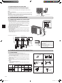
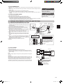
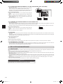
Split-type Air-Conditioner
MXZ-2C52VA
Installation Manual
ForINSTALLER
• Thismanualonlydescribestheinstallationofoutdoorunit.
Wheninstallingtheindoorunit,refertotheinstallationmanualofindoorunit.
JG79A459H02.indd
1
English
2011/03/08
15:18:39
ENGLISH
CONTENTS
. BEFOREINSTALLATION............................................................ 2. OUTDOORUNITINSTALLATION............................................... 3
3. FLARINGWORKANDPIPECONNECTION............................... 3
4. PURGINGPROCEDURES,LEAKTEST,ANDTESTRUN......... 4
5. RELOCATIONANDMAINTENANCE.......................................... 5
Required Tools for Installation
Phillipsscrewdriver
FlaretoolforR40A
Level
GaugemanifoldforR40A
Scale
VacuumpumpforR40A
Utilityknifeorscissors
ChargehoseforR40A
Torquewrench
Pipecutterwithreamer
Wrench(orspanner)
4mmhexagonalwrench
1. BEFORE INSTALLATION
1-1. THE FOLLOWING SHOULD ALWAYS BE OBSERVED FOR SAFETY
• Besuretoread“THEFOLLOWINGSHOULDALWAYSBEOBSERVEDFORSAFETY”beforeinstallingtheairconditioner.
• Besuretoobservethewarningsandcautionsspecifiedhereastheyincludeimportantitemsrelatedtosafety.
• Afterreadingthismanual,besuretokeepittogetherwiththeOPERATINGINSTRUCTIONSforfuturereference.
WARNING
(Couldleadtodeath,seriousinjury,etc.)
n Do not install the unit by yourself (user).
Incompleteinstallationcouldcausefireorelectricshock,injuryduetothe
unitfalling,orleakageofwater.Consultthedealerfromwhomyoupurchasedtheunitoraqualifiedinstaller.
n Perform the installation securely referring to the installation manual.
Incompleteinstallationcouldcausefireorelectricshock,injuryduetothe
unitfalling,orleakageofwater.
n When installing the unit, use appropriate protective equipment and
tools for safety.
Failuretodosocouldcauseinjury.
n Install the unit securely in a place which can bear the weight of the unit.
If the installation location cannot bear the weight of the unit, the unit
couldfallcausinginjury.
n Perform electrical work according to the installation manual and be
sure to use an exclusive circuit. Do not connect other electrical appliances to the circuit.
If the capacity of the power circuit is insufficient or there is incomplete
electricalwork,itcouldresultinafireoranelectricshock.
n Do not damage the wires by applying excessive pressure with parts
or screws.
Damagedwirescouldcausefire.
n Be sure to cut off the main power in case of setting up the indoor P.C.
board or wiring works.
Failuretodosocouldcauseelectricshock.
n Usethespecifiedwirestoconnecttheindoorandoutdoorunitssecurelyandattachthewiresfirmlytotheterminalblockconnecting
sections so the stress of the wires is not applied to the sections.
Incompleteconnectingandsecuringcouldcausefire.
n Donotinstalltheunitinaplacewhereinflammablegasmayleak.
Ifgasleaksandaccumulatesintheareaaroundtheunit,itcouldcause
anexplosion.
n Do not use intermediate connection of the power cord or the extension cord and do not connect many devices to one AC outlet.
Itcouldcauseafireoranelectricshockduetodefectivecontact,defectiveinsulation,exceedingthepermissiblecurrent,etc.
n Besuretousethepartsprovidedorspecifiedpartsfortheinstallation work.
Theuseofdefectivepartscouldcauseaninjuryorleakageofwaterdue
toafire,anelectricshock,theunitfalling,etc.
n When plugging the power supply plug into the outlet, make sure
that there is no dust, clogging, or loose parts in both the outlet and
the plug. Make sure that the power supply plug is pushed completely into the outlet.
Ifthereisdust,clogging,orloosepartsonthepowersupplyplugorthe
outlet,itcouldcauseelectricshockorfire.Ifloosepartsarefoundonthe
powersupplyplug,replaceit.
CAUTION
n Attach the electrical cover to the indoor unit and the service panel
to the outdoor unit securely.
Iftheelectricalcoveroftheindoorunitand/ortheservicepanelofthe
outdoor unit are not attached securely, it could result in a fire or an
electricshockduetodust,water,etc.
n When installing, relocating, or servicing the unit, make sure that
no substance other than the specified refrigerant (R410A) enters
the refrigerant circuit.
Any presence of foreign substance such as air can cause abnormal
pressureriseandmayresultinexplosionorinjury.Theuseofanyrefrigerantotherthanthatspecifiedforthesystemwillcausemechanical
failure, system malfunction, or unit breakdown. In the worst case, this
couldleadtoaseriousimpedimenttosecuringproductsafety.
n Do not discharge the refrigerant into the atmosphere. If refrigerant
leaks during installation, ventilate the room.
Ifrefrigerantcomesincontactwithafire,harmfulgascouldbegenerated.
Refrigerantleakagemaycausesuffocation.Ventilatetheroom.
n Check that the refrigerant gas does not leak after installation has
been completed.
Ifrefrigerantgasleaksindoors,andcomesintocontactwiththeflame
of a fan heater, space heater, stove, etc., harmful substances will be
generated.
n Use appropriate tools and piping materials for installation.
ThepressureofR40Ais.6timesmorethanR22.Notusingappropriatetoolsormaterialsandincompleteinstallationcouldcausethepipes
toburstorinjury.
n When pumping down the refrigerant, stop the compressor before
disconnecting the refrigerant pipes.
If the refrigerant pipes are disconnected while the compressor is runningandthestopvalveisopen,aircouldbedrawninandthepressure
in the refrigeration cycle could become abnormally high. This could
causethepipestoburstorinjury.
n When installing the unit, securely connect the refrigerant pipes
before starting the compressor.
Ifthecompressorisstartedbeforetherefrigerantpipesareconnected
andwhenthestopvalveisopen,aircouldbedrawninandthepressure in the refrigeration cycle could become abnormally high. This
couldcausethepipestoburstorinjury.
n Fastenaflarenutwithatorquewrenchasspecifiedinthismanual.
Iffastenedtootight,aflarenutmaybreakafteralongperiodandcause
refrigerantleakage.
n The unit shall be installed in accordance with national wiring regulations.
n Earth the unit correctly.
Donotconnecttheearthtoagaspipe,waterpipe,lightningrodortelephoneearth.Defectiveearthingcouldcauseelectricshock.
(Couldleadtoseriousinjuryinparticularenvironmentswhenoperatedincorrectly.)
n Install an earth leakage breaker depending on the installation place.
Ifanearthleakagebreakerisnotinstalled,itcouldcauseelectricshock.
n Perform the drainage/piping work securely according to the installation manual.
Ifthereisdefectinthedrainage/pipingwork,watercoulddropfromthe
unit,soakinganddamaginghouseholdgoods.
n Donottouchtheairinletorthealuminumfinsoftheoutdoorunit.
Thiscouldcauseinjury.
n Do not install the outdoor unit where small animals may live.
If small animals enter and touch the electric parts inside the unit, it
could cause a malfunction, smoke emission, or fire. Also, advise user
tokeeptheareaaroundtheunitclean.
1-2. SPECIFICATIONS
Powersupply*
Model
MXZ-2C52VA
Wirespecifications*2
Pipelengthandheightdifference*3,*4,*5,*6,*7,*8
Max.no.ofbends
Max.pipelength
Rated Fre- Breaker
RefrigerantadjustIndoor/outdoor
Max.height
perindoorunit/
Powersupply
perindoorunit/
mentA*0
Voltage quency capacity
connectingwire
difference*9
formultisystem
formulti-system
4-core
2
230V 50Hz
5A 3-core2.0mm
20m/30m
5m
20/30
20g/m
.0/.5mm2
* Connect to the power switch which has a gap of 3 mm or more when
opentointerruptthesourcepowerphase.(Whenthepowerswitchisshut
off,itmustinterruptallphases.)
*2 Use wires in conformity with design 60245 IEC 57. Use the indoor/outdoorconnectingwireinconformitywiththewirespecificationsspecifiedin
theinstallationmanualoftheindoorunit.
*3 Neverusepipeswiththicknesslessthanspecified.Thepressureresistancewillbeinsufficient.
*4 Useacopperpipeoracopper-alloyseamlesspipe.
*5 Becarefulnottocrushorbendthepipeduringpipebending.
*6 Refrigerantpipebendingradiusmustbe00mmormore.
*7 Insulationmaterial:Heatresistingfoamplastic0.045specificgravity
*8 Besuretousetheinsulationofspecifiedthickness.Excessivethickness
may cause incorrect installation of the indoor unit and insufficient thicknessmaycausedewdrippage.
*9 Iftheoutdoorunitisinstalledhigherthantheindoorunit,max.height
differenceisreducedto0m.
*0Ifpipelengthexceeds20m,additionalrefrigerant(R40A)chargeisrequired.(Noadditionalchargeisrequiredforpipelengthlessthan20m.)
Additionalrefrigerant=A×(pipelength(m)-20)
En-
JG79A459H02.indd
1
2011/03/08
15:18:39
1-3. SELECTING OPTIONAL DIFFERENT-DIAMETER JOINTS
Ifthediameterofconnectionpipedoesnotmatchtheportsizeofoutdoorunit,useoptionaldifferent-diameterjointsaccordingtothefollowingtable.
(Unit:mm(inch))
Portsizeofoutdoorunit
MXZ-2C
Liquid/Gas
A,BUNIT
6,35(/4)/9,52(3/8)
Optionaldifferent-diameterjoints(portsizeofoutdoorunit→diameterofconnectionpipe)
6,35(/4)→9,52(3/8):PAC-493PI
9,52(3/8)→2,7(/2):MAC-454JP
9,52(3/8)→5,88(5/8):PAC-SG76RJ
2,7(/2)→9,52(3/8):MAC-A455JP
2,7(/2)→5,88(5/8):MAC-A456JP
Refertotheinstallationmanualofindoorunitforthediameterofconnectionpipeofindoorunit.
1-4.SELECTINGTHEINSTALLATIONLOCATION
•
•
•
•
•
Whereitisnotexposedtostrongwind.
Whereairflowisgoodanddustless.
Whererainordirectsunshinecanbeavoidedasmuchaspossible.
Whereneighboursarenotannoyedbyoperationsoundorhotair.
Whererigidwallorsupportisavailabletopreventtheincreaseofoperationsoundorvibration.
• Wherethereisnoriskofcombustiblegasleakage.
• Wheninstallingtheunit,besuretosecuretheunitlegs.
• Whereitisatleast3mawayfromtheantennaofTVsetorradio.OperationoftheairconditionermayinterferewithradioorTVreceptionin
areaswherereceptionisweak.Anamplifiermayberequiredfortheaffecteddevice.
• Installtheunithorizontally.
• Please install it in an area not affected by snowfall or blowing snow.
Inareaswithheavysnow,pleaseinstallacanopy,apedestaland/or
somebaffleboards.
Note:
It is advisable to make a piping loop near outdoor unit so as to reduce
vibrationtransmittedfromthere.
Note:
Whenoperatingtheairconditionerinlowoutsidetemperature,besure
tofollowtheinstructionsdescribedbelow.
• Neverinstalltheoutdoorunitinaplacewhereitsairinlet/outletside
maybeexposeddirectlytowind.
• Topreventexposuretowind,installtheoutdoorunitwithitsairinlet
sidefacingthewall.
• Topreventexposuretowind,itisrecommendedtoinstallabaffle
boardontheairoutletsideoftheoutdoorunit.
Avoidthefollowingplacesforinstallationwhereairconditionertrouble
isliabletooccur.
• Whereflammablegascouldleak.
• Wherethereismuchmachineoil.
• Saltyplacessuchastheseaside.
• Wheresulfidegasisgeneratedsuchasahotspring.
• Wherethereishigh-frequencyorwirelessequipment.
• WherethereisemissionofhighlevelsofVOCs,includingphthalate
compounds,formaldehyde,etc.,whichmaycausechemicalcracking.
1-5. INSTALLATION DIAGRAM
ACCESSORIES
Checkthefollowingpartsbeforeinstallation.
Aftertheleaktest,applyinsulatingmaterialtightlysothatthereis
nogap.
() Drainsocket
PARTS TO BE PROVIDED AT YOUR SITE
Whenthepipingistobeattachedtoawallcontainingmetals
(tinplated)ormetalnetting,use
achemicallytreatedwooden
piece20mmorthickerbetween
thewallandthepipingorwrap7
to8turnsofinsulationvinyltape
aroundthepiping.
Touseexistingpiping,perform
COOLoperationfor30minutes
andpumpdownbeforeremoving
theoldairconditioner.Remake
flareaccordingtothedimension
fornewrefrigerant.
Openasarule
Morethan500mm
ifthefrontandboth
sidesareopen
Morethan00mm
Morethan200mmifthereare
obstaclestobothsides
Morethan
00mm
(A)
(B)
(C)
(D)
(E)
Powersupplycord*
Indoor/outdoorunitconnectingwire*
Extensionpipe
Wallholecover
Pipingtape
Extensiondrainhose
(F) (orsoftPVChose,5mminner
diameterorhardPVCpipeVP6)
Little
amount
(G) Refrigerationoil
(H)
(I)
(J)
(K)
Putty
Pipefixingband
Fixingscrewfor(I)
Wallholesleeve
SoftPVChose,5mminnerdi(L) ameterorhardPVCpipeVP6for
drainsocket()
2to7
2to7
* Note:
Place indoor/outdoor unit connecting wire (B) and
power supply cord (A) at least m away from the
TVantennawire.
The“Q’ty”for(B)to(K)intheabovetableisquantitytobeusedperindoorunit.
Outdoor unit installation
Morethan350mm
800
50
500
Airinlet
Airoutlet
4-0×2Ovalholes
344.5
Airinlet
285
IMPORTANT NOTES
TocomplywiththerequirementsofAustralianstandardAS/NZS3000
electricalinstallations(wiringrules),theelectricalwiringrequired
betweentheindoorandoutdoorunitsmustbeinstalledbyalicenced
electricalcontractor.
304~325
Openasarule
Morethan500mmiftheback,
bothsidesandtopareopen
(Unit:mm)
Unitsshouldbeinstalledbylicensedcontractoraccordingtolocalcoderequirements.
En-2
JG79A459H02.indd
2
2011/03/08
15:18:39
1-6. DRAIN PIPING FOR OUTDOOR UNIT
Pleaseperformthedrainpipingworkonlywhendrainingfromoneplace.
)Providedrainpipingbeforeindoorandoutdoorpipingconnection.
2)ConnectthesoftPVChose(L)I.D.5mmasshownintheillustration.
3)Makesuretoprovidedrainpipingwithadownhillgradeforeasydrainflow.
Note:
Installtheunithorizontally.
Donotusethedrainsocket()inthecoldregions.Drainmayfreezeanditmakes
thefanstop.
Theoutdoorunitproducescondensateduringtheheatingoperation.Selecttheinstallationplacetoensuretopreventtheoutdoorunitand/orthegroundsfrombeing
wetbydrainwaterordamagedbyfrozendrainwater.
(L)SoftPVChose
()Drainsocket
2. OUTDOOR UNIT INSTALLATION
2-1. CONNECTING WIRES FOR OUTDOOR UNIT
Terminalblockforpowersupply
)Removetheservicepanel.
2)Loosen terminal screw, and connect indoor/outdoor unit connecting
wire(B)fromtheindoorunitcorrectlyontheterminalblock.Becareful
nottomakemis-wiring.Fixthewiretotheterminalblocksecurelyso
thatnopartofitscoreisappeared,andnoexternalforceisconveyed
totheconnectingsectionoftheterminalblock.
3)Firmlytightentheterminalscrewstopreventthemfromloosening.Aftertightening,pullthewireslightlytoconfirmthattheydonotmove.
4)Perform2)and3)foreachindoorunit.
5)Connectpowersupplycord(A).
6)Fixindoor/outdoorunitconnectingwire(B)andpowersupplycord(A)
withthecableclamps.
7)Closetheservicepanelsecurely.Makesurethat3-2.PIPECONNECTIONiscompleted.
• After making connections between both power supply cord (A) and
indoor/outdoorunitconnectingwire(B),besuretofixbothcableand
wirewithcableclamps.
Indoor/outdoorunitconnectingwire
<OUTDOORUNIT>
Terminalblock
Servicepanel
Terminalblockfor
powersupply
5mm
• Be sure to attach each screw to its
correspondent terminal when securing the cord and/or the wire to the
terminalblock.
• Make earth wire a little longer than
others.(Morethan35mm)
• Forfutureservicing,giveextralength
totheconnectingwires.
35mm
Leadwire
POWERSUPPLY
~/N230V50Hz
UNIT
UNIT
<INDOORUNIT>
3. FLARING WORK AND PIPE CONNECTION
3-1. FLARING WORK
)Cutthecopperpipecorrectlywithpipecutter.(Fig.,2)
2)Completelyremoveallburrsfromthecutcrosssectionofpipe.(Fig.3)
• Aim the copper pipe downward while removing burrs to prevent
burrsfromdroppinginthepipe.
3)Removeflarenutsattachedtoindoorandoutdoorunits,thenputthem
onpipehavingcompletedburrremoval.(Notpossibletoputthemon
afterflaringwork.)
4)Flaring work (Fig. 4, 5). Firmly hold copper pipe in the dimension
showninthetable.SelectAmmfromthetableaccordingtothetool
selected.
5)Check
• ComparetheflaredworkwithFig.6.
• Ifflareisnotedtobedefective,cutofftheflaredsectionanddoflaringworkagain.
A(mm)
Pipediameter Nut Clutch
Clutch Wingnut
(mm)
(mm) typetool typetool typetool
forR40A forR22
forR22
ø6.35(/4”) 7
.5to2.0
ø9.52(3/8”) 22
0to0.5 .0to.5
ø2.7(/2”) 26
2.0to2.5
ø5.88(5/8”) 29
TiltedUnevenBurred
Fig.
kgf•cm
3.7to7.7
34.3to4.2
49.0to56.4
73.5to78.4
40to80
350to420
500to575
750to800
Fig.2
Flaringtool
Burr
Copperpipe
Sparereamer
Pipecutter
Tighteningtorque
N•m
Nogood
Good
Copper
pipe
Clutchtype
Fig.3
Wingnuttype
Fig.4
Smoothall
around
Insideisshiningwithoutany
scratches.
Copperpipe
Die
Evenlength
allaround
Flarenut
Fig.5
Fig.6
En-3
JG79A459H02.indd
3
2011/03/08
15:18:41
3-2. PIPE CONNECTION
1)Applyathincoatofrefrigerationoil(G)totheflaredendsofthepipesandthepipeconnectionsoftheoutdoorunit.
2)Alignthecenterofthepipewiththatofthepipeconnectionsoftheoutdoorunit,thenhandtightentheflare
nut3to4turns.
3)Tightentheflarenutwithatorquewrenchasspecifiedinthetable.
•Over-tighteningmaycausedamagetotheflarenut,resultinginrefrigerantleakage.
•Besuretowrapinsulationaroundthepiping.Directcontactwiththebarepipingmayresultinburnsor
frostbite.
3-3. INSULATION AND TAPING
)Coverpipingjointswithpipecover.
2)Foroutdoorunitside,surelyinsulateeverypipingincludingvalves.
3)Usingpipingtape(E),applytapingstartingfromtheentryofoutdoorunit.
• Stoptheendofpipingtape(E)withtape(withadhesiveagentattached).
• Whenpipinghavetobearrangedthroughaboveceiling,closetorwherethetemperatureandhumidity
arehigh,windadditionalcommerciallysoldinsulationtopreventcondensation.
WARNING
When installing the unit, securely
connect the refrigerant pipes before
starting the compressor.
CAUTION
When there are the ports which are
not used, make sure their nuts are
tightened securely.
4. PURGINGPROCEDURES,LEAKTEST,ANDTESTRUN
4-1.PURGINGPROCEDURESANDLEAKTEST
)Remove serviceportcapofstopvalveonthesideoftheoutdoor
unitgaspipe.(Thestopvalvesarefullyclosedandcoveredincaps
intheirinitialstate.)
2)Connectgaugemanifoldvalveandvacuumpumptoserviceportof
stopvalveonthegaspipesideoftheoutdoorunit.
3)Runthevacuumpump.(Vacuumizeformorethan5minutes.)
4)Check the vacuum with gauge manifold valve, then close gauge
manifoldvalve,andstopthevacuumpump.
5)Leave as it is for one or two minutes. Make sure the pointer of
gauge manifold valve remains in the same position. Confirm that
pressuregaugeshows-0.0MPa[Gauge](-760mmHg).
6)Remove gauge manifold valve quickly from service port of stop
valve.
7)Fullyopenallstopvalvesonthegaspipeandtheliquidpipe.Operatingwithoutfullyopeninglowerstheperformanceandthiscauses
trouble.
8)Refer to -2., and charge the prescribed amount of refrigerant if
needed.Besuretochargeslowlywithliquidrefrigerant.Otherwise,
composition of the refrigerant in the system may be changed and
affectperformanceoftheairconditioner.
9)Tightencapofserviceporttoobtaintheinitialstatus.
0)Leaktest
–0.0MPa Compoundpressure
(–760mmHg) gauge(forR40A)
Pressuregauge
Stopvalve
(forR40A)
cap(Torque
Gaugemanifold
9.6to29.4
valve(forR40A)
N•m,200to
300kgf•cm)
HandleHigh
Handle
Stopvalve Low
Chargehose
forLIQUID
(forR40A)
Stopvalve
forGAS
*4to5turns
*Close
*Open
Hexagonalwrench
Serviceportcap
(Torque3.7to7.7N•m,
40to80kgf•cm)
Precautionswhenusing
thecontrolvalve
Vacuumpump
(forR40A)
Whenattachingthecontrolvalveto
theserviceport,valvecoremaydeformorloosenifexcesspressureis
applied.Thismaycausegasleak.
Service
port
Whenattachingthecontrolvalveto
theserviceport,makesurethatthe
valvecoreisinclosedposition,and
then tighten partA. Do not tighten
partAorturnthebodywhenvalve
coreisinopenposition.
Control
valve
Open
Close
A
Body
Chargehose
(forR40A)
4-2.GASCHARGE
Performgaschargetounit.
)Connectgascylindertotheserviceportofstopvalve.
2)Performairpurgeofthepipe(orhose)comingfromrefrigerantgascylinder.
3)Replenish specified amount of the refrigerant, while operating the air conditionerforcooling.
Note:
Incaseofaddingrefrigerant,complywiththequantityspecifiedfortherefrigeratingcycle.
CAUTION:
Whenchargingtherefrigerantsystemwithadditionalrefrigerant,besuretouse
liquid refrigerant.Adding gas refrigerant may change the composition of the
refrigerantinthesystemandaffectnormaloperationoftheairconditioner.Also,
chargetheliquidrefrigerantslowly,otherwisethecompressorwillbelocked.
To maintain the high pressure of the gas cylinder, warm the gas cylinder with
warmwater(under40°C)duringcoldseason.Butneverusenakedfireorsteam.
Indoor
unit
Union
Stopvalve
Liquidpipe
Gaspipe
Indoor
unit
Union
Liquidpipe
Outdoor
unit
Gaspipe
Refrigerantgas
cylinder
operatingvalve
(forR40A)
Serviceport
Gaugemanifold
valve(forR40A)
Chargehose(forR40A)
Refrigerantgascylinder
forR40Awithsiphon
Refrigerant(liquid)
Electronicscalefor
refrigerantcharging
En-4
JG79A459H02.indd
4
2011/03/08
15:18:41
4-3.LOCKINGTHEOPERATIONMODEOFTHEAIRCONDITIONER(COOL,DRY,HEAT)
• Descriptionofthefunction:
With this function, once the operation mode is locked to either COOL/DRY
modeorHEATmode,theairconditioneroperatesinthatmodeonly.
* Changingthesettingisrequiredtoactivatethisfunction.Pleaseexplainabout
thisfunctiontoyourcustomersandaskthemwhethertheywanttouseit.
[How to lock the operation mode]
)Be sure toturnoffthemain power fortheairconditioner beforemaking the
setting.
2)Setthe“2”ofSWontheoutdoorcontrollerboardtoONtoenablethisfunction.
3)TolocktheoperationmodeinCOOL/DRYmode,setthe“”ofSWonthe
outdoorcontrollerboardtoOFF.TolocktheoperationinHEATmode,setthe
sameswitchtoON.
4)Turnonthemainpowerfortheairconditioner.
COOL/DRY
HEAT
4-4.LOWERINGTHEOPERATIONNOISEOFTHEOUTDOORUNIT
• Descriptionofthefunction:
Withthisfunction,theoperatingnoiseoftheoutdoorunitcanbeloweredbyreducingtheoperationload,forexample,duringnighttimeinCOOLmode.
However,pleasenotethatthecoolingandheatingcapacitymaylowerifthisfunctionisactivated.
* Changingthesettingisrequiredtoactivatethisfunction.Pleaseexplainaboutthisfunctiontoyourcustomersandaskthemwhethertheywanttouseit.
[How to lower the operating noise]
)Be sure toturnoffthemain power fortheairconditioner beforemaking the
setting.
2)Setthe“3”ofSWontheoutdoorcontrollerboardtoONtoenablethisfunction.
3)Turnonthemainpowerfortheairconditioner.
Lowertheoperatingnoise
4-5.TESTRUN
• Testrunsoftheindoorunitsshouldbeperformedindividually.Seetheinstallationmanualcomingwiththeindoorunit,andmakesurealltheunitsoperateproperly.
• Ifthetestrunwithalltheunitsisperformedatonce,possibleerroneousconnectionsoftherefrigerantpipesandtheindoor/outdoorunitconnectingwires
cannotbedetected.Thus,besuretoperformthetestrunonebyone.
Makesurethatthefollowingisdone.
• Powerissuppliedtotheunit.
• Stopvalvesareopen.
About the restart protective mechanism
Oncethecompressorstops,therestartpreventivedeviceoperatessothecompressorwillnotoperatefor3minutestoprotecttheairconditioner.
4-6.EXPLANATIONTOTHEUSER
• UsingtheOPERATINGINSTRUCTIONS,explaintotheuserhowtousetheairconditioner(howtousetheremotecontroller,howtoremovetheairfilters,howtoremoveorputtheremotecontrollerintheremotecontrollerholder,howtoclean,precautionsforoperation,etc.).
• RecommendtheusertoreadtheOPERATINGINSTRUCTIONScarefully.
5. RELOCATION AND MAINTENANCE
5-1. PUMPING DOWN
Whenrelocatingordisposingoftheairconditioner,pumpdownthesystemfollowingtheprocedurebelowsothatnorefrigerantisreleasedintotheatmosphere.
)Connectthegaugemanifoldvalvetotheserviceportofthestopvalveonthegaspipesideoftheoutdoorunit.
2)Fullyclosethestopvalveontheliquidpipesideoftheoutdoorunit.
3)Closethestopvalveonthegaspipesideoftheoutdoorunitalmostcompletelysothatitcanbeeasilyclosedfullywhenthepressuregaugeshows0
MPa[Gauge](0kgf/cm2).
4)StarttheemergencyCOOLoperationonalltheindoorunits.
TostarttheemergencyoperationinCOOLmode,disconnectthepowersupplyplugand/orturnoffthebreaker.After5seconds,connectthepower
supplyplugand/orturnonthebreaker,andthenpresstheE.O.SWonce.(TheemergencyCOOLoperationcanbeperformedcontinuouslyforupto30
minutes.)
5)Fullyclosethestopvalveonthegaspipesideoftheoutdoorunitwhenthepressuregaugeshows0.05to0MPa[Gauge](approx.0.5to0kgf/cm2).
6)StoptheemergencyCOOLoperation.
PresstheE.O.SWseveraltimesuntilallLEDlampsturnoff.Refertooperatinginstructionsfordetails.
WARNING
When pumping down the refrigerant, stop the compressor before disconnecting
the refrigerant pipes. The compressor may burst if air etc. get into it.
En-5
JG79A459H02.indd
5
2011/03/08
15:18:41
JG79A459H02.indd
6
2011/03/08
15:18:42
HEADOFFICE:TOKYOBLDG.,2-7-3,MARUNOUCHI,CHIYODA-KU,TOKYO00-830,JAPAN
JG79A459H02
JG79A459H02.indd
7
2011/03/08
15:18:42