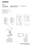
1
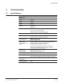
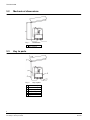
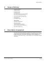
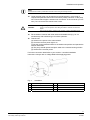
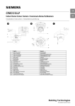
CAHL4010-WU
CAHL4011-WU
Washer Unit
Installation Guide
Building Technologies
Fire Safety & Security Products
Data and design subject to change without notice. / Supply subject to availability.
© 2008 Copyright by Siemens Building Technologies
We reserve all rights in this document and in the subject thereof. By acceptance of the document the recipient acknowledges these rights
and undertakes not to publish the document nor the subject thereof in full or in part, nor to make them available to any third party without our
prior express written authorization, nor to use it for any purpose other than for which it was delivered to him.
Contents
1
1.1
1.2
1.3
1.4
Safety .......................................................................................................5
Target group..............................................................................................5
General safety precautions .......................................................................5
Meaning of the written warning notices ....................................................5
Meaning of the hazard symbols ................................................................5
2
EU Directives ...........................................................................................6
3
3.1
3.2
3.3
Technical data .........................................................................................7
Specifications ............................................................................................7
Mechanical dimensions.............................................................................8
Key to parts ...............................................................................................8
4
Scope of delivery ....................................................................................9
5
Description of equipment.......................................................................9
6
6.1
6.2
Installation and operation ....................................................................10
Installation ...............................................................................................10
Operation ................................................................................................12
7
Maintenance and service .....................................................................13
8
Troubleshooting....................................................................................13
9
Disposal .................................................................................................14
3
Siemens Building Technologies
Fire Safety & Security Products
09.2008
Safety
1
Safety
1.1
Target group
The instructions in this document are designed only for the following target group.
1.2
Target group
Qualification
Activity
Condition of the
product
Installer
Technical training for
building or electrical
installations.
Assembles/installs the
product, individual
components of the
product or replacement
parts.
Components of the
product are not yet
assembled/installed or
need to be replaced.
General safety precautions
z Read the general safety precautions before operating the device.
z Follow all warnings and instructions marked on the device.
z Keep this document for reference.
z Always pass this document on together with the product.
z Please also take into account any additional country-specific, local safety
standards or regulations concerning project planning, operation and disposal of
the product.
Liability claim
z Do not connect the device if it is damaged or any parts are missing.
z Do not make any changes or modifications to the device unless they are
expressly mentioned in this manual and have been approved by the
manufacturer.
z Use only spare parts and accessories that have been approved by the
manufacturer.
1.3
Meaning of the written warning notices
The severity of a hazard is indicated by the following written warning notices.
Signal word
1.4
Type of risk
WARNING
Possible danger of death or severe bodily harm
IMPORTANT
Malfunctioning may result
Meaning of the hazard symbols
The nature of the hazard is indicated by icons.
Warning of a hazard area
5
Siemens Building Technologies
Fire Safety & Security Products
09.2008
EU Directives
2
EU Directives
The product complies with the requirements of the following EU directives. The
EU declaration of conformity is available from:
Siemens Building Technologies
Fire & Security Products GmbH & Co. oHG
76181 Karlsruhe
Germany
EU Directive 2004/108/EC on electromagnetic compatibility
Compliance with the European Directive 2004/108/EC has been proven by testing
according to the following standards:
Emitted interference:
EN 61000-6-3
Resistance to interference:
EN 50130-4
EU Directive 2006/95/EC “Low-Voltage Directive”
Compliance with the European Directive 2006/95/EC has been proven by testing
according to the following standard:
Safety:
EN 60335-1
6
Siemens Building Technologies
Fire Safety & Security Products
09.2008
Technical data
3
Technical data
3.1
Specifications
Mechanical
Length
230 mm
Width
190 mm
Height
300 mm
Weight
Empty: 2 kg
Full: 7 kg
Material
Wall bracket: Stainless steel
Pump unit case: Polycarbonate
Washer container: H.D.P.E thermoplastic
Electrical
Supply voltage
CAHL4010-WU: 230 V AC, 50 Hz
CAHL4011-WU: 24 V AC (±2 V), 50 Hz
Operating power
CAHL4010-WU: 52 W
CAHL4011-WU: 52 W
Supply cable
(not included in the
delivery)
Circular, flexible 2-core cable, approved for outdoor use
Outside diameter: 5 mm min., 13 mm max.
No earth connection should be made.
Conductor size CAHL4010-WU: 0.5 mm2 minimum
Conductor size CAHL4011-WU: 0.75 mm2 minimum
(Unless local codes require greater)
External fuse/
Circuit breaker
CAHL4010-WU: 230 V AC – 3 A
CAHL4011-WU: 24 V AC – 5 A
Operating frequency
50 Hz
Operating temperature
-10 to +40 °C
(with suitable strength car windscreen washer antifreeze)
Non-operating
temperature
-20 to +50 °C
Ingress protection
IP66
7
Siemens Building Technologies
Fire Safety & Security Products
09.2008
Technical data
3.2
Mechanical dimensions
Fig. 1
1
3.3
Dimensions
10 m maximum
Key to parts
Fig. 2
Key to parts
1
Camera housing
2
Nozzle assembly
3
Pump inlet pipe
4
Pump outlet pipe
5
Pump unit
6
Supply cable
8
Siemens Building Technologies
Fire Safety & Security Products
09.2008
Scope of delivery
4
Scope of delivery
z Pump unit with lid
z 5 litre container
z Support bracket
z Retaining strap
z Container cap and inlet pipe assembly
z 5 mm bore tubing (600 mm long)
z 3 mm bore tubing (10 metres long)
z Small parts kit
z Installation Guide
Small parts kit
z Washer nozzle bracket
z Nozzle assembly
z Black threaded outlet adaptor
z M4×10 Stainless steel screws (2 x)
z M4 Fibre washers (2 x)
5
Description of equipment
The washer unit has been designed to operate with any Siemens camera housing
of types CHSL4010 & CHSL4011 with fitted wiper. It assists in keeping the camera
housing window clean. The operation of the washer can be controlled from a
control unit via a telemetry receiver. A self-resetting TOC is incorporated to prevent
overheating.
9
Siemens Building Technologies
Fire Safety & Security Products
09.2008
Installation and operation
6
Installation and operation
6.1
Installation
1.
A readily accessible disconnect device shall be incorporated in the building
installation wiring. In compliance with IEC60335 this device should ensure allpole disconnection and contact separation, providing full disconnection under
overvoltage category III.
2.
As part of the building installation protect the unit via a fuse or circuit breaker
rated at 3 A for CAHL4010-WU 230 V AC or 5 A for CAHL4011-WU 24 V AC.
3.
Mount the washer container bracket to a suitable surface. The type of screws
will depend upon the mounting surface material. The position of the container
should be in accordance with Fig. 2.
NOTE
Do not mount the pump unit more than 10 metres vertically below the camera housing, as this will
impair pump operation.
4.
Remove the pump unit lid (4 off M4 Pozi pan screws).
5.
Insert the supply cable through the loosened sealing entry gland and cord
clamp. The cable must be circular with an outside diameter in the range 5 to
13 mm. If the cable diameter is greater than 8 mm the inner resilient sealing
sleeve only of the gland should be removed. During installation of the cable,
ensure continued compliance with protection class IP66.
6.
Strip the outer insulation back approx. 70–100 mm. Strip both conductors to
the required length (approx. 10 mm). Fit ferrules if required for multi strand
cable. Connect to the 2 way terminal block (polarity unimportant).
7.
Pull cable back through the gland until the outer sheath protrudes 20 mm min
beyond the cord clamp. Tighten both cord clamp screws. Tighten the gland
sealing nut.
8.
Replace the pump unit lid (4 off M4 Pozi pan screws).
9.
Screw the black outlet adaptor into the pump outlet at the bottom of the pump
unit. Do not overtighten. Do not remove the central “loose” insert.
10. Insert the suction tube with filter into the container and fit screw cap.
11. Attach the flexible 5 mm bore tube to the elbow connector at the container
cap.
12. Attach the other end of the 5 mm bore tube to the white (inlet) connector at
the top of the pump unit.
NOTE
Note that some of steps 9 – 12 may have already been carried out during manufacture.
13. Mount the washer nozzle bracket assembly onto the camera housing using
the two M4 x 10 mm screws and fibre washers supplied, as shown in Fig. 3.
Ensure that the screw penetration is not too great before inserting. Fit the
3 mm bore tube to the nozzle inlet taking care not to distort the bracket.
10
Siemens Building Technologies
Fire Safety & Security Products
09.2008
Installation and operation
NOTE
Ensure that the nozzle is positioned so that the hole is facing the housing window.
14. Lower the pipe (tying may be required to provide support), cut to length if
required and push the lower end into the black (outlet) connector on the pump
unit. Ensure that the pipe is inserted until it “bottoms” in the connector (15 mm
nom). Do not remove the central “loose” insert.
Danger of explosion due to alcoholic liquids
There is a risk of explosion when filling the washer container with alcoholic
liquids.
WARNING
z Do not fill the washer container with alcoholic or highly flammable liquids.
15. Fill the washer container with clean water and suitable fluid (e.g. for car
windscreens) with antifreeze type for winter operation.
16. Test the unit:
(a) Switch on the power to the camera head.
(b) Check the receiver power light is on.
(c) Set the receiver address switch to the washer test position and operate the
receiver test button.
(d) The pump should operate and eject water to the camera-housing window.
(e) Switch off the receiver power.
For further connection detail refer to your receiver / controller installation
instructions. Always refer to voltage label before applying power.
Fig. 3
Installation
1
Camera housing
5
Nut
2
Nozzle
6
M4 × 10 screw
3
Plastic washer
7
Fibre washer
4
Shakeproof washer
11
Siemens Building Technologies
Fire Safety & Security Products
09.2008
Installation and operation
6.2
Operation
1.
Regularly check the level of cleaning fluid in the washer container.
Risk of damage to the pump unit due to its running dry
IMPORTANT
The pump unit may be damaged due to lack of water in the container.
z Regularly refill the washer container with cleaning fluid.
2.
The container can be fully removed if required by carefully unbuckling the
retaining strap. After filling this strap should be re-fastened.
3.
The duty cycle (on time : off time) must not exceed 50 %. In addition, the
pump must not be energised for a period longer than 1 minute at a time.
12
Siemens Building Technologies
Fire Safety & Security Products
09.2008
Maintenance and service
7
Maintenance and service
The following maintenance guidelines should be observed.
1 month after installation and
every 6 months thereafter
Check the tightness and security of all external fastenings
6 monthly checks
Check electrical cables and pipes for signs of wear. Replace where necessary.
Check that the cables are not fouling on any obstruction.
NOTE
This installation guide cannot cover all conceivable cases of installation, operation or maintenance.
Should you require further information or should special problems occur which are not discussed in
adequate detail in the installation guide, please request the required information from your local
Siemens office.
We must also point out that the contents of this installation guide do not constitute a part of an earlier
or existing agreement. Neither do they constitute or amend any earlier or existing commitment or legal
relationship. All obligations on the part of Siemens result from the relevant purchase agreement which
also contains the complete and solely valid warranty regulations. This installation guide neither
extends nor restricts these contractual warranty regulations.
8
Troubleshooting
In the event of failure check the other camera housing assembly functions for
example, pan / tilt operation etc. This proves the receiver is working.
If the receiver is functioning check the correct output voltage to the pump is present
at the junction box when operated via the control system (options 230 V AC or
24 V AC).
If this voltage is present check the pump is operating and that the hose pipes are
connected correctly.
If the receiver is not functioning check the instructions provided with the receiver
unit.
Prolonged usage of the pump motor may result in failure (see section 6.2
Operation).
Do not operate the pump “dry”.
Check that the hole of the nozzle is pointing at the camera housing glass.
If the pump has had an extensive run period its thermal cutout may have operated.
Allow the pump to cool down.
13
Siemens Building Technologies
Fire Safety & Security Products
09.2008
Disposal
9
Disposal
All electrical and electronic products should be disposed of separately from the
municipal waste stream via designated collection facilities appointed by the
government or the local authorities.
This crossed-out wheeled bin symbol on the product means the product is covered by
the European Directive 2002/96/EC.
The correct disposal and separate collection of your old appliance will help prevent
potential negative consequences for the environment and human health. It is a
precondition for reuse and recycling of used electrical and electronic equipment. For
more detailed information about disposal of your old appliance, please contact your
city office, waste disposal service or the shop where you purchased the product.
14
Siemens Building Technologies
Fire Safety & Security Products
09.2008
Issued by
Siemens Building Technologies
Fire & Security Products GmbH & Co. oHG
D-76181 Karlsruhe
www.buildingtechnologies.siemens.com
Document no.
A6V10087770
Edition
24.09.2008
© 2008 Copyright by
Siemens Building Technologies
Data and design subject to change without notice.
Supply subject to availability.