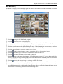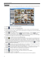
1
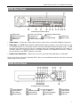
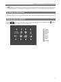
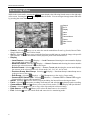
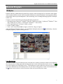
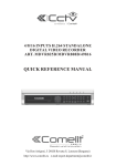
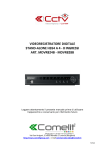
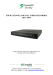
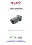
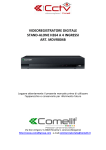
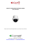
Digital Video Recorder art. IPHYB008A-IPHYB016A DVR Rear Panel 16-Channel DVR Rear Panel Video Input HD/SD Out Selector RS232C Port Video Out Video Loop Through Factory Reset Switch Network Port iSCSI Port eSATA Port Alarm Input/Output Audio In/Out RS485 Port Power Cord Connector Video Input: Connect the coaxial cables from the video sources to the BNC Video In connectors. Video Out: An HDMI (High-Definition Multimedia Interface) connector is provided so that you can use an HDMI monitor as your primary monitor when in the HD (High Definition) display mode. A VGA connector is provided so that you can use a standard, multi-sync computer monitor as your primary or secondary monitor. Connect the primary or secondary monitor to the Video Out connector. Connect the spot monitor to the SPOT connector as needed. Power Cord Connector: Connect the AC power cord to the DVR and then to a wall outlet. No special tools are required to install the DVR. Refer to the installation manuals for the other items that make up part of your system. DVR Front Panel 16-Channel DVR Front Panel Camera Buttons Arrow Buttons Panic Button Monitor Button LED Jog Dial, Shuttle Ring Playback Buttons PTZ Button Freeze Button Bookmark Button Display Button Menu Button Enter Button Alarm Button Zoom Button USB Port 1 Quick Reference Manual Camera Buttons: Pressing the individual camera buttons will cause the selected camera to display full screen. Buttons 1 to 9 are also used to enter passwords. Jog Dial: When in the playback mode, you can play video forward image-by-image by turning the Jog Dial clockwise and backward image-by-image by turning the Jog Dial counterclockwise. When in the Setup mode, you can change number values by highlighting the item in the menu and turning Jog Dial clockwise or counterclockwise to increase or decrease the number. Shuttle Ring: The Shuttle Ring only functions in the Playback mode. The Shuttle Ring is spring loaded and returns to the center position when released. Turning the ring clockwise plays video forward. Turning the ring counterclockwise plays video backward. Playback speed varies with the amount the ring is turned. The playback speeds are , , , x0.5, , , and . When you release the ring, it snaps back to the center position and the video pauses. Arrow Buttons: These buttons are used to navigate through menus and GUI. You can also use them to change numbers by highlighting a number in the menu and using the Up and Down arrow buttons to increase or decrease the number’s value. These buttons are also used to control Pan and Tilt when in the PTZ mode. Enter Button: The button selects a highlighted item or completes an entry that you have made during system setup. Playback Buttons – Backward: When in the pause mode, pressing the button moves to the previous image. The button is also used to Zoom Out while in the PTZ mode. – Forward: When in the pause mode, pressing the button moves to the next image. The button is also used to Zoom In while in the PTZ mode. – Rewind: Pressing the button plays video backward at high speed. Pressing the button again toggles and . The button is also used for Near Focus in the PTZ mode. the playback speed from , button plays back video at regular speed. The screen displays when – Play/Pause: Pressing the the DVR is in the Pause mode and the screen displays when the DVR is playing back video. The button is also used for Far Focus in the PTZ mode. – Fast Forward: Pressing the button plays video forward at high speed. Pressing the button again toggles the playback speed from , and . The button is also used to load a Preset View in the PTZ mode. button while in the Live Monitoring mode enters the Search mode. – Search/Stop: Pressing the Pressing the button while in the Search mode returns the DVR to the Live Monitoring mode. The button is also used to save Presets while in the PTZ mode. PTZ Button: Pressing the button enters the PTZ (Pan/Tilt/Zoom) mode which allows you to control properly configured cameras. Alarm Button: Pressing the button resets the DVR’s outputs including the internal buzzer during an alarm, and displays the event log when you are in the live monitoring mode unless there is an active alarm. Panic Button: Pressing the button starts panic recoding of all camera channels, and pressing the button again will stop panic recording. Freeze Button: Pressing the button freezes the current live screen. Bookmark Button: When in the playback mode, pressing the button adds the current playback point to the bookmark list or moves to the registered bookmark point. Zoom Button: Pressing the button zooms the current image on the screen. A PIP with a rectangle temporarily displays showing what area of the screen has been enlarged. You can use the arrow buttons to move the rectangle to another area. Monitor Button: Pressing the button toggles the monitor selection between Primary, Secondary and Spot. Display Button: Pressing the button toggles between different display formats (2x2, 3x2, 3x3, 4x3 and 4x4). Menu Button: In the Live Monitoring mode and Search mode, pressing the button displays the menu icons on the right edge of the screen. 2 Digital Video Recorder art. IPHYB008A-IPHYB016A USB Port: The USB port is provided to connect external hard disk or flash drives for video clip copying or system upgrades. A USB mouse or PostScript™ USB printer can be connected to the USB port. Turning on the Power Connecting the power cord to the DVR turns on the unit. The unit takes approximately 60 seconds to initialize. Setting Up the System Press the MENU button or move the mouse pointer on the right edge of the screen and then select in the Live Monitoring menu to enter the setup screen. (Setup) System Record Network Event Device Display Status Camera 3 Quick Reference Manual Map of Setup Screens NOTE: 4 Refer to User’s Manual (on CD) for the setup instructions for details. Digital Video Recorder art. IPHYB008A-IPHYB016A Live Monitoring As soon as the DVR completes its initialization process, it will begin showing live video on the attached monitor and playing live audio through the attached speaker. The default mode is to display all cameras at once. Pressing any camera button will cause that camera to display full screen. It displays live video and plays live audio until the user enters another mode. While in the live monitoring mode, pressing the MENU button displays the following Live Monitoring menu on the right edge of the screen. Pressing the MENU button again hides the menu. You can navigate through menus and items by pressing the arrow buttons. Login/Logout Monitor Display Freeze Alarm Panic Sequence Camera Menu Search Setup Login/Logout: Selecting (Login) accesses the Login screen, and you will be asked to select a User and enter the password to log into the system. Selecting (Logout) menu displays the Logout screen asking you to confirm whether or not you want to log out the current user. Monitor: Selecting (Monitor) allows you to select the monitor from Primary, Secondary and Spot. Display – Local Camera: Selecting (Display) → Local Camera and choosing the camera number displays the selected local camera full screen. – Network Camera: Selecting (Display) → Network Camera and choosing the camera number displays the selected network camera full screen. – Screen Format: Selecting (Display) → Screen Format and choosing the screen mode displays the cameras in the selected multiview screen mode (2x2, 3x2, 3x3, 4x3 or 4x4). – Previous Group, Next Group: Selecting (Display) → Previous Group or Next Group moves to the previous or next page. – Edit Group: Selecting (Display) → Edit Group enters to the Active Cameo mode. – Camera OSD, Status OSD: Selecting (Display) → Camera OSD or Status OSD toggles Camera OSD or Status OSD On and Off. Freeze: Selecting will freeze the current image on the screen until you select again. Alarm: Selecting resets the DVR’s outputs including the internal buzzer during an alarm. Panic: Selecting starts panic recording of all cameras, and selecting again stops panic recording. Sequence: Selecting causes the cameras to display sequentially, and selecting again exits the Sequence mode. Camera Menu: Selecting allows you to control PTZ, Zoom, Audio, Color Control and Spot Monitor. You can also select the stream and check the information of network cameras. Search: Selecting exits the live monitoring mode and enters the search mode. Setup: Selecting enters the Main Setup screen. 5 Quick Reference Manual Searching Video While in the search mode, pressing the MENU button displays the following Search menu on the right edge of the screen. Pressing the MENU button again hides the menu. You can navigate through menus and items by pressing the arrow buttons. Search Go To Display Alarm Panic Camera Menu Export Data Source Exit Search: Selecting allows you to select the search method from Event Log Search, Record Table Search, Motion Search and Text-In Search. Go To: Selecting allows you to search the first/last recorded image or search the image with specific date and time. You can also add the current playback point to the bookmark list. Display – Local Camera: Selecting (Display) → Local Camera and choosing the camera number displays the selected local camera full screen. – Network Camera: Selecting (Display) → Network Camera and choosing the camera number displays the selected network camera full screen. – Screen Format: Selecting (Display) → Screen Format and choosing the screen mode displays the cameras in the selected multiview screen mode (2x2, 3x2, 3x3, 4x3 or 4x4). – Previous Group, Next Group: Selecting (Display) → Previous Group or Next Group moves to the previous or next page. – Edit Group: Selecting (Display) → Edit Group enters to the Active Cameo mode. – Camera OSD, Status OSD: Selecting (Monitor) → Camera OSD or Status OSD toggles Camera OSD or Status OSD On and Off. Alarm: Selecting resets the DVR’s outputs including the internal buzzer during an alarm. Panic: Selecting starts panic recording of all cameras, and selecting again stops panic recording. Camera Menu: Selecting allows you to control Zoom, Audio, Text-In Display and Spot Monitor. Export: Selecting allows you to copy video clips and print a selected image. Data Source: Selecting allows you to select the data source to be searched. Exit: Selecting exits the search mode and enters the live monitoring mode. 6 Digital Video Recorder art. IPHYB008A-IPHYB016A Remote Program RASplus RASplus (Remote Administration System Plus) program, which is designed to be used with remote digital video recorders (DVRs, network video transmitters and network cameras included), is an integrated software program that controls system management, video monitoring, video recording and image playback of multiple remote sites. Computer system requirements for using the RASplus program are: Operating System: Microsoft® Windows® XP x86 (32 Bit) (Service Pack 3), Microsoft® Windows® Vista x86 (32 Bit) (Service Pack 1) or Microsoft® Windows® 7 x86 (32 Bit) CPU: Intel Pentium IV (Celeron) 2.4GHz or faster RAM: 512MB or higher VGA: AGP, Video RAM 8MB or higher (1024x768, 24bpp or higher) After installing the RASplus software, you will find the RASplus shortcut icon RASplus program by double clicking the icon. on the desktop. Run the Live Monitoring To connect a remote site on the Watch screen, select the site or camera you want to connect to in the Remote Site, Favorite Sites or Map panel and then drag and drop it in the desired position on the screen. The icon will be displayed on each Watch screen. To disconnect the current connection, select the site or camera you want to disconnect to in the Remote Sites, Favorite Sites or Map panel or on the screen and then click the button on the toolbar or select Disconnect from the System drop-down menu. 7 Quick Reference Manual Playback and Search To connect a remote site on the Search screen, select the site or camera you want to connect to in the Remote Site or Favorite Sites panel and then drag and drop it in the desired position on the screen. The icon will be displayed on each Search screen. The remote site connection on the Search screen will automatically be disconnected if there is no activity for a specified amount of time. Click the button on the toolbar or select Disconnect from the System drop-down menu to disconnect the current connection manually. Panic Recording Clicking the button on the toolbar starts panic recording of cameras currently displayed on the Watch screen. Clicking the button again stops panic recording. Clicking the button on the toolbar initiates the Record Player program and plays video saved in the recording folder designated during the System setup. WebGuard WebGuard allows you to access a remote DVR, monitor live video images and search recorded video using Internet Explorer web browser anytime from virtually anywhere. Computer system requirements for using the WebGuard program are: Operating System: Microsoft® Windows® XP x86 (32 Bit) (Service Pack 3), Microsoft® Windows® Vista x86 (32 Bit) (Service Pack 1), Microsoft® Windows® 7 x86 (32 Bit) CPU: Intel Pentium III (Celeron) 600MHz or faster RAM: 128MB or higher VGA: 8MB or higher (1024x768, 24bpp or higher) Internet Explorer: Version 6.0 or later Start Internet Explorer on your local PC. You can run the WebGuard program by entering the following information in the address field. – “http://IP address:port number” (The DVR IP address and the WebGuard port number (default: 12088) set in the Network setup screen (WebGuard tab)) – Or, “http://DVRNS server address/DVR name” (The DVRNS server address and the DVR name registered on the DVRNS server) – Or, “http://www.dvronline.net” (Entering the DVR IP address or the DVR name will be required when logging in) 8 Digital Video Recorder art. IPHYB008A-IPHYB016A Web Monitoring WebWatch is a remote web monitoring program that allows you to monitor live video transmitted in real-time from the remote DVR. ① ② ③ ④ ⑤ ⑥ ⑦ ⑧ ⑨ ⑩ ⑪ ⑫ ⑬ Click the to log out the WebGuard program. Click the to access to the web search mode. Position the mouse pointer on the WebWatch logo to see the version of the WebGuard program. The DVR information window displays the login information of WebGuard. Click the screen format to select the desired display mode. When changing the screen format, the selected camera on the current screen will be located in the first cell of the new layout. Click the camera button to select the camera to be viewed. Click the to adjust the brightness, contrast, saturation and hue of monitoring image. Click the to control pan, tilt and zoom of the camera from a remote site. Click the to control alarm out devices at the remote site. to set up the image drawing mode, OSD display and beep on/off. You can adjust the display Click the speed by changing the image drawing mode, select OSD information to be displayed on the screen, and turn the DVR’s internal buzzer on and off from a remote site. to save the current image as a bitmap or JPEG file format. Click the The event status window at the bottom displays a list of events that were detected from the remote site. Selecting a camera on the screen and clicking the right mouse button displays the text menu screen. You can change the camera title, enable audio communication with the remote site, change the image aspect ratio, turn on the interlacing filter and eliminate aliasing effects. 9 Quick Reference Manual Web Search WebSearch is a remote web search program that allows you to search recorded video on the remote DVR. ① ② ③ ④ ⑤ ⑥ ⑦ ⑧ ⑨ ⑩ ⑪ ⑫ ⑬ ⑭ ⑮ 10 Click the to log out the WebGuard program. Click the to access to the web monitoring mode. Position the mouse pointer on the WebSearch logo to see the version of the WebGuard program. The DVR information window displays the time information of recorded data on the remote DVR and login information of WebGuard. to blur, sharpen, equalize and interpolate playback images. Click the to zoom out Click the or zoom in the recorded image. Click the to adjust the brightness of the recorded images. The playback function buttons include fast backward, pause, play, fast forward, go to the first image, go to the previous image, go to the next image, and got to the last image. Click the screen format to select the desired display mode. Click the to enter the time-lapse search mode which allows you to search for recorded data by time and then play back images found within the time parameters. The Timetable window located at the bottom displays the time information for the image of the date selected on the calendar. If more than one video stream in the same time range, you can select the video stream you want to search. Clicking a specific time displays the image recorded at that time on the screen. Selecting the allows you to display an image from a specific time. Click the to enter the event search mode which allows you to search for event log entries using specific conditions and play back the images associated with those event entries. Click the to set up the image drawing mode and OSD display. You can adjust the display speed by changing the image drawing mode, and select OSD information to be displayed on the screen. Click the to save any video clip of recorded data as an executable file. Click the to save the current image in a bitmap or JPEG file format. Click the to print the current image on a printer connected to your computer. Click the to reload the recording data. The Timetable displays recorded data of the selected camera by time (in hour segments). Digital Video Recorder art. IPHYB008A-IPHYB016A Selecting a camera on the screen and clicking the right mouse button displays the text menu screen. You can change the camera title, play audio, change the image aspect ratio, turn on the interlacing filter and eliminate aliasing effects. Via Don Arrigoni, 5 24020 Rovetta S. Lorenzo (Bergamo) http://www.comelitgroup.com E mail: [email protected] 11