1
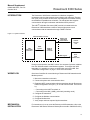
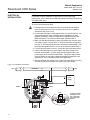
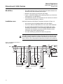
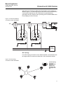
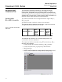
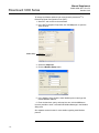
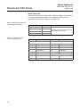
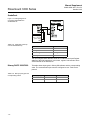
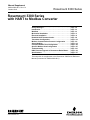
Manual Supplement 00809-0300-4811, Rev CA October 2010 Rosemount 3300 Series Rosemount 3300 Series with HART to Modbus Converter Safety Messages . . . . . . . . . . . . . . . . . . . . . . . . . . . . . . . . . page 1-2 Introduction . . . . . . . . . . . . . . . . . . . . . . . . . . . . . . . . . . . . . page 1-3 Workflow . . . . . . . . . . . . . . . . . . . . . . . . . . . . . . . . . . . . . . . page 1-3 Mechanical Installation . . . . . . . . . . . . . . . . . . . . . . . . . . . page 1-3 Electrical Installation . . . . . . . . . . . . . . . . . . . . . . . . . . . . . page 1-4 Establish HART Communication . . . . . . . . . . . . . . . . . . . . page 1-8 Transmitter Configuration . . . . . . . . . . . . . . . . . . . . . . . . . page 1-10 Modbus Communication Protocol Configuration . . . . . . page 1-11 Alarm Handling . . . . . . . . . . . . . . . . . . . . . . . . . . . . . . . . . . page 1-19 Common Modbus Host Configuration . . . . . . . . . . . . . . . page 1-22 Specific Modbus Host Configuration . . . . . . . . . . . . . . . . page 1-27 Troubleshooting . . . . . . . . . . . . . . . . . . . . . . . . . . . . . . . . . page 1-31 HMC Firmware Upgrade in Rosemount Radar Master . . page 1-32 Specifications . . . . . . . . . . . . . . . . . . . . . . . . . . . . . . . . . . . page 1-37 This instruction is a supplement to the Rosemount 3300 Series Reference Manual (Document No. 00809-0100-4811). www.rosemount.com Manual Supplement 00809-0300-4811, Rev CA October 2010 Rosemount 3300 Series SAFETY MESSAGES Procedures and instructions in this section may require special precautions to ensure the safety of the personnel performing the operations. Information that raises potential safety issues is indicated by a warning symbol ( ). Please refer to the following safety messages before performing an operation preceded by this symbol. Failure to follow safe installation and service guidelines could result in death or serious injury • Make sure the transmitter is installed by qualified personnel and in accordance with applicable code of practice. • Use the equipment only as specified in the Rosemount 3300 Series Reference Manual (Document No. 00809-0100-4811), and in this Manual Supplement. Failure to do so may impair the protection provided by the equipment. • Do not perform any services other than those contained in this manual unless you are qualified. Explosions could result in death or serious injury • Verify that the operating environment of the transmitter is consistent with the appropriate hazardous locations specifications. • To prevent ignition of flammable or combustible atmospheres, disconnect power before servicing. • Before connecting a HART® based communicator in an explosive atmosphere, make sure the instruments in the loop are installed in accordance with intrinsically safe or non-incendive field wiring practices. • To avoid process leaks, only use o-ring designed to seal with the corresponding flange adapter. Electrical shock can result in death or serious injury • Avoid contact with the leads and terminals. High voltage that may be present on leads can cause electrical shock. • Make sure the main power to the Rosemount 3300 Series transmitter is off and the lines to any other external power source are disconnected or not powered while wiring the transmitter. Probes with non-conducting surfaces • 1-2 Probes covered with plastic and/or with plastic discs may generate an ignition-capable level of electrostatic charge under certain extreme conditions. Therefore, when the probe is used in a potentially explosive atmosphere, appropriate measures must be taken to prevent electrostatic discharge. Manual Supplement 00809-0300-4811, Rev CA October 2010 INTRODUCTION Rosemount 3300 Series The Rosemount 3300 Series transmitter is a Modbus compatible measurement device that supports communication with a Remote Terminal Unit (RTU) using a subset of read, write, and diagnostic commands used by most Modbus compatible host controllers. The transmitter also supports communication through Levelmaster and Modbus ASCII protocols. The HART® to Modbus Converter (HMC) module is located inside the Rosemount 3300 transmitter enclosure and provides power to and communicates with the transmitter through a HART interface. Figure 1-1. System Overview 3300 transmitter enclosure Modbus and Levelmaster communication HART signals 3300 transmitter electronics Remote Terminal Unit HART to Modbus Converter HART signals RCT/ Field Communicator During normal operation, the HMC “mirrors” the contents of process variables from the 3300 transmitter to the Modbus registers. To configure the 3300 transmitter, it is possible to connect a configuration tool to the HMC. See “Transmitter Configuration” on page 1-10 for more information. WORKFLOW Overview of workflow for commissioning a Rosemount 3300 transmitter with Modbus protocol: 1. Mount the transmitter on the tank. 2. Connect the power and communication wires. 3. Establish HART communication with the transmitter through Rosemount Radar Configuration Tools (RCT), or a Field Communicator. This is done by: • Connecting to the HART terminals, or • Connecting to the MA (+)/MB (-) terminals (tunneling mode) 4. Configure the transmitter. 5. Configure the Modbus communication. 6. Configure Modbus host. 7. Verify output values as reported by the transmitter. MECHANICAL INSTALLATION For instructions on how to mount the Rosemount 3300 transmitter, refer to the Rosemount 3300 Series Reference Manual (Document No. 00809-0100-4811). 1-3 Manual Supplement 00809-0300-4811, Rev CA October 2010 Rosemount 3300 Series ELECTRICAL INSTALLATION NOTE For general electrical installation requirements, including grounding requirements, refer to Rosemount 3300 Series Reference Manual (Document No. 00809-0100-4811). To connect the Rosemount 3300: 1. Disconnect/shut off the electrical power to transmitter head and then open the instrument cover. Do not remove the cover in an explosive atmosphere with a live circuit. 2. Pull the cable through the cable gland/conduit. For the RS-485 bus, use shielded twisted pair wiring, preferably with an impedance of 120 (typically 24 AWG) in order to comply with the EIA-485 standard and EMC regulations. The maximum cable length is 4000 ft/1200 m. 3. Make sure that the transmitter housing is grounded, then connect wires according to Figure 1-2 and Table 1-1. Connect the lead that originates from the “A” line from the RS-485 bus to the terminal marked MB (-), and the lead that originates from the “B” line to the terminal marked MA (+). 4. If it is the last transmitter on the bus, connect the 120 termination resistor. 5. Connect the leads from the positive side of the power supply to the terminal marked PWR +, and the leads from the negative side of the power supply to the terminal marked PWR -. The power supply cables must be suitable for the supply voltage and ambient temperature, and approved for use in hazardous areas, where applicable. 6. Attach and tighten the housing cover. Tighten the cable gland, then plug and seal any unused terminals, and connect the power supply. Figure 1-2. Field Wiring Connections 120 RS-485 Bus B 120 A Power Supply HART + HART - 120 In case it is the last transmitter on the bus, connect the 120termination resistor 1-4 Manual Supplement 00809-0300-4811, Rev CA October 2010 Connection Terminals Rosemount 3300 Series The connection terminals are described in Table 1-1 below: Table 1-1. Connection Terminals Connector label Description HART + Positive HART connector HART - Negative HART connector MA (+) Modbus RS-485 B connection (RX/TX+)(1) MB (-) Modbus RS-485 A connection (RX/TX-)(1) PWR + Positive Power input terminal PWR - Comment Connect to PC with RCT software, Field Communicator, or other HART configurators. Connect to RTU Apply +8 Vdc to +30 Vdc Negative Power input terminal (max. rating) (1) The designation of the connectors do not follow the EIA-485 standard, which states that RX/TX- should be referred to as 'A' and RX/TX+ as 'B'. Figure 1-3. Connection Terminals for Rosemount 3300 with HART to Modbus Converter HART + HART - 1-5 Manual Supplement 00809-0300-4811, Rev CA October 2010 Rosemount 3300 Series RS-485 Bus Installation cases • The 3300 transmitter does not provide electrical isolation between the RS-485 bus and the transmitter power supply • Maintain a bus topology and minimize stub length • Figure 1-4 identifies multidrop wiring topology, where up to 32 devices may be wired on one RS-485 bus • The RS-485 bus needs to be terminated once at each end, but should not be terminated elsewhere on the bus Install the Rosemount 3300 Series Transmitters as shown in Figure 1-4. • Use common ground for Modbus Master and Power Supply • The Power cables and RS-485 Bus are in the same cable installation • An ground cable is installed and shall be used (cable size ≥4 mm according to IEC60079-14, or size according to applicable national regulations and standards). A properly installed threaded conduit connection may provide sufficient ground. • The cable shielding is grounded at master site (optional) NOTE The HMC equipped transmitter contains intrinsically safe circuits that require the housing to be grounded in accordance with national and local electrical codes. Failure to do so may impair the protection provided by the equipment. Figure 1-4. Multidrop Connection of 3300 Transmitters 120 120 B A RS-485 Bus Modbus Master Z Power Supply Internal Ground Screw Internal Ground Screw External Ground Screw 1-6 External Ground Screw Manual Supplement 00809-0300-4811, Rev CA October 2010 Rosemount 3300 Series Alternatively, the Rosemount 3300 Series Transmitters can be installed as shown in Figure 1-5. If this wiring layout is used, there is an increased risk for communication disturbances due to differences in potential between grounding points. By using the same grounding point for Modbus Master and Power Supply, this risk is reduced. Figure 1-5. Alternative Multidrop Connection of 3300 Transmitters 120 120 B A RS-485 Bus Modbus Master Z Internal Ground Screw Internal Ground Screw External Ground Screw External Ground Screw Power Supply Star Topology For a Star Topology Connection of the 3300 transmitters, the transmitter with the longest cable run needs to be fitted with a 120- termination resistor. Figure 1-6. Star Topology Connection of 3300 Transmitters For Star Topology connection, connect the 120 termination resistor to the transmitter with the longest cable run. 1-7 Manual Supplement 00809-0300-4811, Rev CA October 2010 Rosemount 3300 Series ESTABLISH HART COMMUNICATION The Rosemount 3300 Series transmitter can be configured using the Rosemount Radar Configuration Tools (RCT) PC software, or a Field Communicator. Configuration is done by sending HART commands through the HART to Modbus Converter (HMC) to the 3300 transmitter electronics. To establish HART communication, connect to the MA (+)/MB (-) terminals, or to the HART terminals. Both alternatives are described below. Connect to the MA (+)/MB (-) terminals The 3300 level transmitter can be configured with RCT using the MA (+), MB (-) terminals. An RS-485 Converter is required to connect to the transmitter. The transmitter will try to establish communication using different protocols during 20 second timeslots from time of startup. Figure 1-7. RS-485 Communication after startup Modbus RTU HART 20 seconds 20 seconds 0s 20 s Configured protocol (Modbus RTU, HART Levelmaster, 20 seconds or Modbus ASCII) 20 seconds 40 s 60 s Configured protocol (Modbus RTU, Levelmaster, or Modbus ASCII) 20 seconds 80 s Time 100 s The transmitter will continue to use a communication protocol once communication has been established. To configure the 3300 level transmitter using RCT and the MA (+), MB (-) terminals, do the following: 1. Connect the RS-485 Converter to the MA (+), MB (-) terminals. 2. Connect the power wires (or cycle power) to the transmitter. 3. Wait 20 seconds. 4. In RCT, select Poll Address in the drop-down list (also see note below). Click the button to the left of the drop-down list to start polling. 1-8 Manual Supplement 00809-0300-4811, Rev CA October 2010 Rosemount 3300 Series 5. After connection to the transmitter, perform the necessary configuration. 6. When the configuration is completed, disconnect the RS-485 Converter, connect the Modbus communication wires, and cycle power to the transmitter 7. Verify communication between the transmitter and the RTU is established (can take up to 60 seconds from startup). NOTE If there are multiple 3300 Modbus units on the bus with HART address 1, it will not be possible to establish communication (by default the transmitters have HART address 1). To establish communication in this case, make sure the 3300 transmitter is alone on the bus. Disconnect or turn off power from any other devices. Connect to the HART terminals To configure the 3300 transmitter, connect the communicator or PC to the HART terminals using a HART modem, see Figure 1-3 on page 1-5. Both the configuration tool and the RS-485 bus can be connected simultaneously. Configuration data is sent with HART commands through the HMC to the 3300 transmitter electronics, as illustrated in Figure 1-1 on page 1-3. Note that the power supply must be connected during configuration, see also “Electrical Installation” on page 1-4. NOTE Measurement data is not updated to the Modbus Master when a configuration tool is connected. 1-9 Manual Supplement Rosemount 3300 Series TRANSMITTER CONFIGURATION 00809-0300-4811, Rev CA October 2010 Configuration data such as Tank Height, Upper Null Zone, dielectric constants, and other basic parameters are configured in the same way as for a standard Rosemount 3300 Series transmitter. For more information, see the Rosemount 3300 Series Quick Installation Guide (Document No. 00825-0100-4811). Make sure that the measurement unit of the Primary Variable (PV) matches the configuration of the Modbus Host since the transmitter output value does not include any information on associated measurement units. For further information on basic configuration, see the Rosemount 3300 Series Reference Manual (Document No. 00809-0100-4811). NOTE The 3300 transmitter with Modbus protocol is configured to HART address 1 at factory. This reduces power consumption by locking the analog output at 4 mA. 1-10 Manual Supplement 00809-0300-4811, Rev CA October 2010 MODBUS COMMUNICATION PROTOCOL CONFIGURATION Rosemount 3300 Series The Rosemount 3300 Series transmitter can communicate with RTUs using Modbus RTU (often referred to as just “Modbus”), Modbus ASCII, and Levelmaster (also known as “ROS,” “Siemens,” or “Tank” protocol). Table 1-2. List of RTUs’ Supported Protocols RTU Protocols ABB Totalflow Modbus RTU, Levelmaster Bristol ControlWave Micro Modbus RTU Emerson Process Management ROC800 Series Modbus RTU, Levelmaster(1) Emerson Process Management FloBoss 107 Modbus RTU, Levelmaster(1) Kimray DACC 2000/3000 Levelmaster ScadaPack Modbus RTU Thermo Electron Autopilot Modbus RTU, Levelmaster (1) Levelmaster protocol should be used when using the Emerson Process Management Digital Level Sensor (DLS) User Program or Application Module together with the device. Use Modbus RTU in other cases. Modbus ASCII is not commonly used, since it doubles the amount of bytes for the same message as the Modbus RTU. If you do not have any of these RTUs, check your RTU manual to see which protocols it supports. Using RCT to change communication parameters NOTE To change Modbus communication parameters, the Rosemount 3300 Series transmitter must use HART address 1, the default address. NOTE After changing communication parameters, disconnect the HART modem and wait at least 60 seconds for the change to take effect. In case the MA (+)/MB (-) terminals are used for connection to the HMC, disconnect the RS-485 Converter, cycle power to the transmitter and wait up to 60 seconds for the change to take effect. 1-11 Manual Supplement Rosemount 3300 Series 00809-0300-4811, Rev CA October 2010 To change the Modbus address and communication parameters(1) in Rosemount Radar Configuration Tools (RCT): 1. Start RCT and connect to the transmitter. 2. In the RCT workspace Project Bar, click the Setup icon to open the Setup window. Modbus Setup 3. Select the Output tab. 4. Click the Modbus Setup button. 5. In the Modbus Setup window, select Modbus protocol and type the desired Modbus address. 6. Enter the baud rate, parity, and stop bits, then click the OK button. It is also possible to enter a user-defined Modbus Message in the Modbus String area. See separate sections below for more details regarding each Modbus protocol. (1) 1-12 The Modbus Setup function is available in RCT version 2.03.0002 and later. Manual Supplement 00809-0300-4811, Rev CA October 2010 Using a Field Communicator to change communication parameters Rosemount 3300 Series NOTE To change Modbus communication parameters, the Rosemount 3300 Series transmitter must use HART address 1, the default address. NOTE After changing communication parameters, disconnect the Field Communicator and wait up to 60 seconds for the change to take effect. The Modbus communication parameters can be changed by entering a text string in the HART Message parameter. See separate sections below for details regarding each Modbus protocol and what strings to use. When using the Field Communicator, the Message Area is reached using HART command [1,4,1,6]. Modbus RTU Communication Setup Table 1-3. Modbus RTU Communication Parameters The Rosemount 3300 Series is configured with the default Modbus RTU address 246, and with the following Modbus RTU communication parameter default settings: Parameter Baud Rate Start Bits (1) (1) Default Value Configurable Values 9600 1200, 2400, 4800, 9600, 19200 One One Eight Eight Parity None None, Odd, Even Stop Bits One One or Two Address range 246 1-255 Data Bits (1) Start Bits and Data Bits cannot be changed. To reset the communication parameters to default Modbus RTU settings, use the following Modbus Message: HMC Modbus RTU Parameter Configuration Example You want to use address 44 for the 3300 transmitter, and the following communication parameters are used by the host: Table 1-4. Communication Parameters Used by the Host (example) Parameter Baud Rate Value 4800 Start Bits One Data Bits Eight Parity Odd Stop Bits Two 1-13 Manual Supplement 00809-0300-4811, Rev CA October 2010 Rosemount 3300 Series To configure the 3300 transmitter to communicate with the Host in this example, the following text string is written to the HART Slave 1 Message Area: HMC A44 B4800 PO S2. HMC: These three letters are used for safety and will eliminate the risk of changing the configuration data by mistake. A44: A indicates that the following number is the new address (address 44). Leading zeroes are not needed. B4800: B indicates that the following number is the new baud rate (1200, 2400, 4800, 9600, 19200). PO: P identifies the following letter as parity type (O = odd, E = even, and N = none). S2: S indicates that the following figure is the number of stop bits (1 = one, 2 = two). Only values that differ from the current values need to be included. For example, if only the address is changed, the following text string is written into the 3300 (HART Slave 1) Message Area: HMC A127, indicates that 127 is the new address. Levelmaster Communication Setup Table 1-5. Levelmaster Communication Parameters The default and configurable parameter values can be found in Table 1-5. Parameter Default value Configurable value Baud Rate 9600 1200, 2400, 4800, 9600, 19200 Start Bits One One Data Bits Seven Seven, Eight Parity None None, Odd, Even Stop Bits One One or Two Address 1 1-99 To reset the communication parameters to default Levelmaster settings, use the following Modbus Message: HMC M2 1-14 Manual Supplement 00809-0300-4811, Rev CA October 2010 Rosemount 3300 Series Levelmaster Parameter Configuration Example You want to use address 2 for the 3300 transmitter and the host uses the following parameters: Table 1-6. Parameters Used by the Host (in case of Levelmaster, example) Parameter Baud Rate Value 9600 Start Bits One Data Bits Seven Parity None Stop Bits One To configure the 3300 transmitter to communicate with the Host in this example, the following text string is written to the Modbus Message area. HMC M2 A2 B9600 D7 PN S1. NOTE Include all the parameters when writing to the message area. Note that an address must be unique on the bus. HMC: These three letters are used for safety and will eliminate the risk of changing the configuration data by mistake. M2: This means that the Levelmaster protocol is to be used. A2: A indicates that the following is the new address (address 2). Leading zeroes are not needed. B9600: B indicates that the following number is the new baud rate (1200, 2400, 4800, 9600, 19200). D7: D indicates that the following data bits are to be used (7 = seven, 8 = eight). PN: P identifies the following letter as parity type (O = odd, E = even, and N = none). S1: S indicates that the following figure is the number of stop bits (1 = one, 2 = two). Note: Start Bits are not configurable and cannot be set. 1-15 Manual Supplement 00809-0300-4811, Rev CA October 2010 Rosemount 3300 Series In Table 1-7 and Table 1-8 is a description of the implemented functions of Levelmaster protocol in the HMC. Table 1-7. Implemented Functions of Levelmaster Protocol Input format Description Output format UnnN? Return ID number UnnNnnCcccc UnnNmm Set ID number UnnNOKCcccc UnnF? Return number of floats UnnFxCcccc UnnFx? Set number of floats UnnFOKCcccc Unn? Return floats and other data UnnDddd.ddFfffEeeee WwwwCcccc(1) (1) In this case, number of floats is set to 1. If number of floats is set to 2, the Output Format would be: UnnDddd.ddDddd.ddFfffEeeeeWwwwCcccc NOTE If one float is sent, it is “Float1”. If two floats are sent, it is “Float 1” before “Float 0”. Table 1-8. Letters and Expressions Used in Previous Tables Letter Description nn nn is used to identify slave to respond, nn is a number 00-99 or ** (wildcard). The EmulCtrl Address Holding register can be configured to a higher value than 99. In that case, the address will be truncated to 99. mm mm is the new ID number for the slave; mm is a number 00-99. x x is the number of floats returned when slave receives Unn?, x is a number 0-2. cccc Is the 16 bit CRC checksum, cccc are hexadecimal characters. ddd.dd ddd.dd is the distance value from slave 1. Note that the first d can also be a ‘-’ (minus). Float 1 Slave 1 PV. Float 0 Slave 1 SV. fff The temperature value. Configured by Holding Register 3208 in HMC.(1) eeee An error value. Bit 0: Invalid SV value (Float 0). Bit 8: Invalid Temperature value. Bit 12: Invalid PV value (Float 1). Wwww A warning value, not used in this implementation. (1) Any of the four available variables from any of the five HART slaves can be selected as the temperature source. The least four significant bits (bit 0-3) select the variable number. Bits 4-7 select the HART slave address. If invalid values are used, the temperature value will be invalid, with no Error bit set. For example, if we want to use FV from HART Slave 3 as temperature source, we have to write the value 34 Hex (52 decimal). 1-16 Manual Supplement 00809-0300-4811, Rev CA October 2010 Modbus ASCII Communication Setup Table 1-9. Modbus ASCII Communication Parameters Rosemount 3300 Series The parameter, default, and configurable values are shown in Table 1-9 below. Parameter Default value Configurable values Baud Rate 9600 1200, 2400, 4800, 9600, 19200 Start Bits One One Data Bits Seven Seven, Eight Parity None None, Odd, even Stop Bits One One or Two Address 1 1-255 To reset the communication parameters to default Modbus ASCII settings, use the following Modbus Message: HMC M1 Modbus ASCII Parameter Configuration Example You want to use address 246 for the 3300 transmitter and the host uses the following parameters: Table 1-10. Parameters Used by the Host (in case of Modbus ASCII, example) Parameter Value Baud Rate 9600 Start Bits One Data Bits Seven Parity None Stop Bits One To configure the 3300 transmitter to communicate with the Host in this example, the following text string is written to the Modbus Message area. HMC M1 A246 B9600 D7 PN S1. NOTE Include all the parameters when writing to the message area. Note that an address must be unique on the bus. HMC: These three letters are used for safety and will eliminate the risk of changing the configuration data by mistake. M1: This means that the Modbus ASCII protocol is to be used. A246: A indicates that the following number is the new address (address 246). Leading zeroes are not needed. B9600: B indicates that the following number is the new baud rate (1200, 2400, 4800, 9600, 19200). 1-17 Manual Supplement Rosemount 3300 Series 00809-0300-4811, Rev CA October 2010 D7: D indicates that the following data bits are to be used (7 = seven, 8 = eight). PN: P identifies the following letter as parity type (O = odd, E = even, and N = none). S1: S indicates that the following figure is the number of stop bits (1 = one, 2 = two). Note: Start Bits are not configurable and cannot be set. 1-18 Manual Supplement 00809-0300-4811, Rev CA October 2010 ALARM HANDLING Rosemount 3300 Series NOTE If the Modbus communication setup has been changed, but the transmitter has not yet started to use the new configuration, then you need to disconnect the HART modem and wait up to 60 seconds for the change to take effect. In case the MA (+)/MB (-) terminals are used for connection to the HMC, disconnect the RS-485 Converter, cycle power to the transmitter and wait up to 60 seconds for the change to take effect. The Modbus communication settings will otherwise be lost if you write a new message to the transmitter. The output from the Modbus transmitter in case of an error (such as a field device malfunction) can be configured. The values for Modbus registers corresponding to PV, SV, TV, and QV will be changed accordingly (applicable registers in area 1300, 2000, 2100, and 2200). The default alarm output value for each protocol is defined on the next page. Configuring alarm output value is optional. Use the Modbus Message to configure the alarm output. To enter a Modbus Message in RCT, do the following (Modbus RTU shown): 1. Start RCT and connect to the transmitter. 2. In the RCT workspace Project Bar, click the Setup icon to open the Setup window. Modbus Setup 1-19 Manual Supplement 00809-0300-4811, Rev CA October 2010 Rosemount 3300 Series 3. Select the Output tab. 4. Click the Modbus Setup button. 5. Enter the Modbus Message, and click OK. See below for available Alarm Output Modbus Messages. Modbus RTU Message HMC EN HMC EF HMC EU U-0.1 Alarm Output Not a number (NaN), default Freeze, hold last value User defined value, -0.1 in this example Levelmaster Message HMC M2 EH HMC M2 EL HMC M2 EF HMC M2 EU U0 Alarm Output High value, 999.99, default Low value, -99.99 Freeze, hold last value User defined value (range -99.99 to 999.99), 0 in this example Modbus ASCII Message HMC M1 EN HMC M1 EF HMC M1 EU U-0.1 Alarm Output Not a number (NaN), default Freeze, hold last value User defined value (range -99.99 to 999.99), -0.1 in this example NOTE After changing the Alarm Output configuration, disconnect the HART modem and wait up to 60 seconds for the change to take effect. In case the MA (+)/MB (-) terminals are used for connection to the HMC, disconnect the RS-485 Converter, cycle power to the transmitter, and wait up to 60 seconds for the change to take effect. Verify Alarm Output 1-20 To verify the Alarm Output, simulate a device failure by removing the transmitter head. For instructions on removing the transmitter head and re-attaching it, see the Rosemount 3300 Series Reference Manual (Document No. 00809-0100-4811). Manual Supplement 00809-0300-4811, Rev CA October 2010 Use status information to evaluate measurement validity Rosemount 3300 Series The transmitter updates status information about the current measurement, and this status information is available as a bitfield register through Modbus communication. By monitoring the status information it is possible to determine if the current measurement output value is valid. See “Common Modbus Host Configuration” on page 1-22 for details about the individual status bits. Use Heartbeat to detect errors By reading and evaluating the Heartbeat value from the device, it is possible to verify that the communication link between the transmitter, HMC, RTU and even the control system communicating with the RTU is working. Assign Heartbeat to one of the transmitter variables (SV, TV, or QV). Heartbeat is increased by one for each measurement cycle in the device (until it eventually starts over at zero again). In case this value is not updated, it means that the communication link is broken. 1-21 Manual Supplement 00809-0300-4811, Rev CA October 2010 Rosemount 3300 Series COMMON MODBUS HOST CONFIGURATION When using Modbus RTU or Modbus ASCII, the registers to receive status and variables must be configured in the host system. The transmission of single-precision (4 bytes) IEEE 754 floating point numbers can be rearranged in different byte orders specified by the Floating Point Format Code. The format code information, stated for each Remote Terminal Unit (RTU) respectively, specifies which registers to poll from the 3300 transmitter in order for the RTU to correctly interpret floating point numbers. The byte transmission order for each format code is demonstrated in Table 1-11 below. Table 1-11. Byte Transmission Order is specified by the Floating Point Format Code Format Code Byte transmission order Description 0 [AB] [CD] Straight word order, most significant byte first 1 [CD] [AB] Inverse word order, most significant byte first 2 [DC] [BA] Inverse word order, least significant byte first 3 [BA] [DC] Straight word order, least significant byte first NOTE Some Modbus hosts cannot read the information described here using Input Registers (Modbus function code 4). The Input Register information can also be read using Holding Register (Function code 3). In this case, Input Register number + 5000 is used as Holding Register number. Between host system and device, it is recommended to use 60 seconds or less between polls, and three retries. Input Registers The register area starting with 1300 can be configured to have any of the four format codes. The configuration is done by setting FloatingPointFormatCode register (holding register 3000) to 0-3, as shown in Table 1-11. This configuration can be done with the Rosemount Radar Master program. NOTE Depending on the slave number the 3300 transmitter is using, different registers must be used with the default slave number being 1. Slave number is determined by the HART address. 1-22 Manual Supplement 00809-0300-4811, Rev CA October 2010 Table 1-12. Output Variables for the Configurable Floating Point Format (default code 1) Rosemount 3300 Series Register Name Register Number Note Slave 1 Status Conf 1300 Bit information in bitfield. Bit 0: Invalid Measurement Slave 1 PV. Bit 1: Invalid Measurement Slave 1 Non PV. Bit 2: Invalid Measurement Slave 1 Non PV. Bit 3: Invalid Measurement Slave 1 Non PV. Bit 14: HART bus busy (slave in burst or other master present) Bit 15: HTM Task not running (option not available). Note: Bit 1-3 is set when Invalid Measurement of Slave 1 Non PV. i.e. all three bits are set simultaneously. Slave 1 PV Conf 1302 Primary variable from slave 1 represented in IEEE 754 format, using the byte order set in the FloatingPointFormatCode register. Slave 1 SV Conf 1304 Secondary variable from slave 1 represented in IEEE 754 format, using the byte order set in the FloatingPointFormatCode register. Slave 1 TV Conf 1306 Tertiary variable from slave 1 represented in IEEE 754 format, using the byte order set in the FloatingPointFormatCode register. Slave 1 FV Conf 1308 Fourth variable from slave 1 represented in IEEE 754 format, using the byte order set in the FloatingPointFormatCode register. Slave 2 data 1310-1318 Same data as for Slave 1. Slave 3 data 1320-1328 Same data as for Slave 1. Slave 4 data 1330-1338 Same data as for Slave 1. Slave 5 data 1340-1348 Same data as for Slave 1. The Rosemount 3300 Series register area starting with register 2000 is used for hosts that require Floating Point Format Code 0 (see Table 1-13). Floating Point Format Codes 2 and 3 use register areas 2100 and 2200, respectively (see Table 1-14 and Table 1-15). 1-23 Manual Supplement 00809-0300-4811, Rev CA October 2010 Rosemount 3300 Series Table 1-13. Output Variables for Floating Point Format Code 0 Table 1-14. Output Variables for Floating Point Format Code 2 1-24 Register Name Register Number Note Slave 1 Status 2000 Bit information in bitfield: Bit 0: Invalid Measurement Slave 1 PV. Bit 1: Invalid Measurement Slave 1 SV. Bit 2: Invalid Measurement Slave 1 TV. Bit 3: Invalid Measurement Slave 1 FV. Bit 14: HART bus busy (slave in burst or other master present) Bit 15: HTM Task not running (option not available). Note: Bit 1-3 is set when Invalid Measurement of Slave 1 Non PV, i.e. all three bits are set simultaneously. Slave 1 PV 2002 Primary variable from slave 1 represented in IEEE 754 format, using Floating Point Format Code 0. Slave 1 SV 2004 Secondary variable from slave 1 represented in IEEE 754 format, using Floating Point Format Code 0. Slave 1 TV 2006 Tertiary variable from slave 1 represented in IEEE 754 format, using Floating Point Format Code 0. Slave 1 FV (QV) 2008 Fourth variable from slave 1 represented in IEEE 754 format, using Floating Point Format Code 0. Register Name Register Number Note Slave 1 Status 2100 Bit information in bitfield: Bit 0: Invalid Measurement Slave 1 PV. Bit 1: Invalid Measurement Slave 1 SV. Bit 2: Invalid Measurement Slave 1 TV. Bit 3: Invalid Measurement Slave 1 FV. Bit 14: HART bus busy (slave in burst or other master present) Bit 15: HTM Task not running (option not available). Note: Bit 1-3 is set when Invalid Measurement of Slave 1 Non PV, i.e. all three bits are set simultaneously. Slave 1 PV 2102 Primary variable from slave 1 represented in IEEE 754 format, using Floating Point Format Code 2. Manual Supplement 00809-0300-4811, Rev CA October 2010 Rosemount 3300 Series Register Name Table 1-15. Output Variables for Floating Point Format Code 3 Register Number Note Slave 1 SV 2104 Secondary variable from slave 1 represented in IEEE 754 format, using Floating Point Format Code 2. Slave 1 TV 2106 Tertiary variable from slave 1 represented in IEEE 754 format, using Floating Point Format Code 2. Slave 1 FV (QV) 2108 Fourth variable from slave 1 represented in IEEE 754 format, using Floating Point Format Code 2. Register Name Register Number Note Slave 1 Status 2200 Bit information in bitfield: Bit 0: Invalid Measurement Slave 1 PV. Bit 1: Invalid Measurement Slave 1 SV. Bit 2: Invalid Measurement Slave 1 TV. Bit 3: Invalid Measurement Slave 1 FV. Bit 14: HART bus busy (slave in burst or other master present) Bit 15: HTM Task not running (option not available). Note: Bit 1-3 is set when Invalid Measurement of Slave 1 Non PV, i.e. all three bits are set simultaneously. Slave 1 PV 2202 Primary variable from slave 1 represented in IEEE 754 format, using Floating Point Format Code 3. Slave 1 SV 2204 Secondary variable from slave 1 represented in IEEE 754 format, using Floating Point Format Code 3. Slave 1 TV 2206 Tertiary variable from slave 1 represented in IEEE 754 format, using Floating Point Format Code 3. Slave 1 FV (QV) 2208 Fourth variable from slave 1 represented in IEEE 754 format, using Floating Point Format Code 3. 1-25 Manual Supplement 00809-0300-4811, Rev CA October 2010 Rosemount 3300 Series Measurement Units Measurement units for the various HART slaves are stored in input registers as a Unit Code presented in Table 1-16. Conversion from Unit Code to measurement unit is given in Table 1-17 on page 1-26. Table 1-16. Measurement units and corresponding input registers Table 1-17. Conversion of Unit Code to Measurement Unit Register Name Register Number Slave 1 PV Units 104 Slave 1 SV Units 108 Slave 1 TV Units 112 Slave 1 FV (QV) Units 116 Unit Code Note See Table 1-17 for conversion from Unit Code to Measurement Unit. Measurement Unit Unit Code Volume 1-26 Measurement Unit Length 40 US Gallon 44 Feet 41 Liters 45 Meters 42 Imperial Gallons 47 Inches 43 Cubic Meters 48 Centimeters 46 Barrels 49 Millimeters 111 Cubic Yards 112 Cubic Feet 33 Degree Fahrenheit 113 Cubic Inches 32 Degree Celsius Temperature Manual Supplement 00809-0300-4811, Rev CA October 2010 SPECIFIC MODBUS HOST CONFIGURATION Rosemount 3300 Series The Remote Terminal Unit needs to be configured to communicate and correctly interpret data when reading input registers from the Rosemount 3300 Series transmitter. Baud Rate The specified Baud Rates below are recommendations. If other Baud Rates are used, make sure that the 3300 and the RTU are configured for the same communication speed. Floating Point Format Code See Section “Common Modbus Host Configuration” on page 1-22. RTU Data Type The RTU Data Type specifies which configuration to use in the RTU in order for the RTU to correctly interpret a floating point number transmitted from the 3300 transmitter with Modbus. Input Register Base Number Data registers in the 3300 transmitter with Modbus are numbered exactly as they are transmitted in the Modbus communication. Some RTUs use different naming conventions and to configure the RTU to poll the correct registers from the 3300 Modbus, an Input Register Base Number is stated for each RTU respectively. E.g. if the input register base number is 1 for the RTU, the 3300 Modbus input register 1302 has to be entered in the RTU address as input register 1303. Emerson Process Management ROC800 Series Figure 1-8. Wiring Diagram for Connecting 3300 Modbus to Emerson Process Management ROC800 Series ROC800 Series RS-485 3300 Modbus MA (+) MB (-) PWR + PWR - A (RX/TX+) B (RX/TX-) Y Z COM Power Supply + 8 to + 30 Vdc (max. rating) GND Table 1-18. Parameter Values (in case of Emerson Process Management ROC800 Series) Parameter Value Baud Rate 9600 Floating Point Format Code 0 RTU Data Type Conversion Code 66 Input Register Base Number 0 The Input Register Base Number needs to be added to the Input Register address of the 3300 transmitter. In this case, register 1300 needs to have 1300 entered as the address. 1-27 Manual Supplement 00809-0300-4811, Rev CA October 2010 Rosemount 3300 Series Emerson Process Management FloBoss 107 Figure 1-9. Wiring Diagram for Connecting 3300 Modbus to Emerson Process Management FloBoss 107 FloBoss 107 RS-485 3300 Modbus MA (+) MB (-) PWR + PWR - A B NC NC PWR GND Power Supply + 8 to + 30 Vdc (max. rating) GND Table 1-19. Parameter Values (in case of Emerson Process Management FloBoss 107) Parameter Value Baud Rate 9600 Floating Point Format Code 0 RTU Data Type Conversion Code 66 Input Register Base Number 0 The Input Register Base Number needs to be added to the Input Register address of the 3300 transmitter. In this case, register 1300 needs to have 1300 entered as the address. ABB TotalFlow Figure 1-10. Wiring diagram for connecting 3300 Modbus to ABB TotalFlow Table 1-20. Parameter Values (in case of ABB TotalFlow) Parameter Value Baud Rate 9600 Floating Point Format Code 0 RTU Data Type 16 Bit Modicon Input Register Base Number 1 The Input Register Base Number needs to be added to the Input Register address of the 3300 transmitter. In this case, register 1302 needs to have 1303 entered as the address etc. 1-28 Manual Supplement 00809-0300-4811, Rev CA October 2010 Rosemount 3300 Series Thermo Electron Autopilot Figure 1-11. Wiring Diagram for Connecting 3300 Modbus to Thermo Electron Autopilot Power Supply + 8 to + 30 Vdc (max. rating) GND Table 1-21. Parameter Values (in case of Thermo Electron Autopilot) Parameter Value Baud Rate 9600 Floating Point Format Code 1 RTU Data Type IEEE Flt 2R Input Register Base Number 0 The Input Register Base Number needs to be added to the Input Register address of the 3300 transmitter. In this case, register 1302 needs to have 1302 entered as the address etc. Bristol ControlWave Micro Figure 1-12. Wiring Diagram for Connecting 3300 Modbus to Bristol ControlWave Micro Power Supply + 8 to + 30 Vdc (max. rating) DB9 Male GND Table 1-22. Parameter Values (in case of Bristol ControlWave Micro) Parameter Value Baud Rate 9600 Floating Point Format Code 2 (FC 4) RTU Data Type 32-bit registers as 2 16-bit registers Input Register Base Number 1 The Input Register Base Number needs to be added to the Input Register address of the 3300 transmitter. In this case, register 1302 needs to have 1303 entered as the address etc. 1-29 Manual Supplement 00809-0300-4811, Rev CA October 2010 Rosemount 3300 Series ScadaPack Figure 1-13. Wiring Diagram for Connecting 3300 Modbus to SCADAPack 32 Power Supply + 8 to + 30 Vdc (max. rating) REF Table 1-23. Parameter Values (in case of SCADAPack 32) Parameter Value Baud Rate 9600 Floating Point Format Code 0 RTU Data Type Floating Point Input Register Base Number 30001 The Input Register Base Number needs to be added to the Input Register address of the 3300 transmitter. In this case, register 1302 needs to have 31303 entered as the address etc. Kimray DACC 2000/3000 Table 1-24. Kimray Input Types and Corresponding Values 1-30 This table shows input types in Kimray IMI software and the corresponding value. The communication port must be configured to use “Tank Levels” protocol. Kimray Inp type 3300 variable Tank Level1 PV ddd.dd.alt. -dd.dd Format Tank Level2 SV ddd.dd.alt -dd.dd Manual Supplement 00809-0300-4811, Rev CA October 2010 TROUBLESHOOTING Rosemount 3300 Series No communication on RS-485 bus (MA (+), MB (-)) • Check that the cables are connected • Check that PWR+ is connected to + and PWR- is connected to - on the power supply • Make sure the 3300 transmitter is supplied with 8-30 Vdc (max. rating) • Try alternating MA (+)/MB (-)if you are unsure of the polarity • If an RS-485 converter is used, make sure it is properly installed and configured • The last 3300 transmitter may need a terminating 120-resistor connected between MA (+) and MB (-) No 3300 communication in RCT • Using HART+, HART• HART modem is not properly connected • Polling address is incorrect in RCT (default 1) • Using MA (+), MB (-) • See No communication on RS-485 bus • Polling address is incorrect in RCT (default 1) • Cycle the power and wait 20 seconds before polling No communication with Modbus RTU protocol • See No communication on RS-485 bus • Make sure the “Modbus Communication Protocol Configuration” is done properly • Make sure the Modbus RTU address is unique on the bus • Cycle the power and try to connect • Check the RTU communication settings No communication with Modbus ASCII protocol • See No communication on RS-485 bus • Make sure the “Modbus Communication Protocol Configuration” is done properly • Make sure the Modbus ASCII address is unique on the bus • Cycle the power, waiting 40 seconds before communication begins • Check the RTU communication settings No communication with Levelmaster protocol • See No communication on RS-485 bus • Make sure the “Modbus Communication Protocol Configuration” is done properly • Make sure the Levelmaster address is unique on the bus • Cycle the power, waiting 40 seconds before communication begins • Check the RTU communication settings 1-31 Manual Supplement Rosemount 3300 Series HMC FIRMWARE UPGRADE IN ROSEMOUNT RADAR MASTER 00809-0300-4811, Rev CA October 2010 The HMC’s firmware is upgraded using Rosemount Radar Master (RRM). A detailed description on how to carry out the firmware upgrade is shown on the following pages. NOTE All settings in the HMC will be lost after upgrading the transmitter. Reconfiguration of Modbus communication setup and alarm handling is required after completing the upgrade. NOTE During firmware upgrade, the HMC Modbus RTU address must be 246, the default address. Make sure to disconnect other Modbus RTU devices that are connected and have address 246. NOTE Do not interrupt communication between the PC and the 3300 level transmitter during the firmware upload. 1. Start RRM and select Communication Preferences in the View menu. 2. Navigate to the Modbus tab and use the following settings: • Modem: RS-485 • Baudrate: According to configuration in HMC (default 9600) • Stop Bits: According to configuration in HMC (default 1) • Parity: According to configuration in HMC (default None) • Handshake: RTS/CTS • Response Timeout: 1000 ms • Retries: 3 3. Select Enable Modbus Communication and click OK. 1-32 Manual Supplement 00809-0300-4811, Rev CA October 2010 Rosemount 3300 Series 4. If the HMC is configured for Modbus ASCII or Levelmaster communication cycle the power to the transmitter (the HMC will then communicate using Modbus RTU for 20 seconds and under that time it is possible to connect with RRM). 5. Open the Search Device window and make sure Modbus is selected in the Protocol list. 6. Search for HMCs by selecting “Scan Address Range”, and choose a start and end address for Modbus. The default HMC Modbus address is 246. 7. Click the Start Scan button. 8. Click OK to connect when the device is found. 9. From the Service menu, choose the Enter Service Mode option. 10. Type password, “admin”. 1-33 Manual Supplement Rosemount 3300 Series 00809-0300-4811, Rev CA October 2010 11. From the Service menu, choose the Upload Firmware option. 12. Click Browse. 13. Select the upgrade “.cry” file. 14. Click Open. 1-34 Manual Supplement 00809-0300-4811, Rev CA October 2010 Rosemount 3300 Series 15. Click the Upload button to start the firmware upgrade. 16. When upload is finished, select Diagnostics in the Tools menu. Checksum 17. Click Device Errors and check for “Checksum”. 18. If it is on the list, choose the Factory Settings option from the Tools menu. 1-35 Manual Supplement Rosemount 3300 Series 00809-0300-4811, Rev CA October 2010 19. Select All and click OK. 20. Select “Yes”. NOTE An error message might be displayed when performing the Reset to Factory Settings operation. The operation has been successful if the checksum error has been cleared. 21. Select Restart in the Tools menu to restart the HMC. 22. The checksum error should no longer be present (select Diagnostics in the Tools menu to verify, see Step 16). If it still persists, follow the next steps. 23. Select View Holding Registers in the Service menu and write the value 16760 to register 65510. 24. Restart the HMC. 25. If the HMC is configured for Modbus ASCII or Levelmaster communication after upload has been completed, proceed with the following: 1. Close RRM and disconnect the RS-485 converter from the HMC. 2. Cycle the power to the HMC to have it exit Modbus RTU communication mode. 1-36 Manual Supplement 00809-0300-4811, Rev CA October 2010 Rosemount 3300 Series SPECIFICATIONS Table 1-25. Specifications Power supply 8-30 Vdc (max. rating) Power consumption < 0.5 W (with HART address=1) < 1.2 W (incl. four HART slaves) Signal wiring Two-wire half duplex RS-485 Modbus. Use shielded twisted pair wiring, preferably with an impedance of 120(typically 24 AWG), in order to comply with EIA-485 standard and EMC regulations. Power supply cabling The power supply cables must be suitable for the supply voltage and ambient temperature, and approved for use in hazardous areas, where applicable. Ground (common mode) voltage limit ±7V Bus termination Standard RS-485 bus termination per EIA-485 See the Rosemount 3300 Series Reference Manual (Document No. 00809-0100-4811) for further specifications. 1-37 Manual Supplement 00809-0300-4811, Rev CA October 2010 Rosemount 3300 Series The Emerson logo is a trademark and service mark of Emerson Electric Co. Rosemount and the Rosemount logotype are registered trademarks of Rosemount Inc. All other marks are the property of their respective owners. Standard Terms and Conditions of Sale can be found at www.rosemount.com\terms_of_sale © 2010 Rosemount Inc. All rights reserved. Emerson Process Management Rosemount Measurement 8200 Market Boulevard Chanhassen MN 55317 USA Tel (USA) 1 800 999 9307 Tel (International) +1 952 906 8888 F +1 952 949 7001 00809-0300-4811 Rev CA 10/10 Emerson Process Management Shared Services Ltd Heath Place Bognor Regis West Sussex PO22 9SH England Tel +44 (1243) 863 121 Fax +44 (1243) 867 554 Emerson Process Management Asia Pacific Pte Ltd 1 Pandan Crescent Singapore 128461 Tel +65 6777 8211 Fax +65 6777 0947 Service Support Hotline: +65 6770 8711 Email: [email protected]