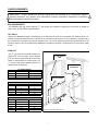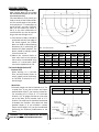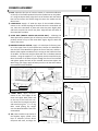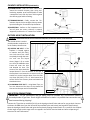
1
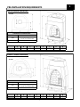
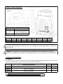
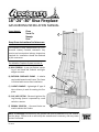
18”-24”-30” Kiva Fireplace GAS BURNING INSTALLATION MANUAL Orno Santa Fe Navajo Zuni Keep these instructions for future use. Frame Models: C This fireplace is to be installed ONLY by a construction industry licensed contractor. Any permits and construction industry inspections required for installation should be obtained by this contractor. B The Adobelite Fireplace System consists of: A) KIVA FIREBOX - A pre-cast firebox consisting of real hand laid firebrick and lightweight concrete. A B) EXTERIOR FIREPLACE FRAME - A tubular steel and diamond-mesh frame. The frame is finished with stucco after installation. C) B-VENT CHIMNEY - Lightweight 6” type BVent chimney is used for venting the fireplace. D D) GAS LOG SYSTEM - Electronic Ignition Gas Log Burning System is operated by a wall switch or remote. E) FIREBOX PEDESTAL - Concrete blocks are used to elevate the firebox. E NOTE: All warnings are outlined in this manual and must be adhered to by the installer and the buyer. Failure to do so will nullify the manufacturer’s warranty, and may cause serious fire hazard. RV-103012 WARNINGS AND GENERAL SAFETY PRECAUTIONS IMPORTANT: THESE INSTRUCTIONS MUST BE LEFT WITH HOMEOWNER ALL WARNINGS OUTLINED IN THIS MANUAL MUST BE STRICTLY ADHERED TO BY THE INSTALLER AND HOMEOWNER. FAILURE TO FOLLOW these installation instructions will VOID THE WARRANTY and may cause a serious FIRE HAZARD. This fireplace is to be installed ONLY by a construction industry licensed contractor. Any permits and construction industry inspections required for installation should be obtained by this contractor. Fully READ and UNDERSTAND all instructions carefully before beginning installation. DO NOT modify your fireplace in any way. Any modification will void the warranty and create a potential fire hazard. Before burning your first fire, fully read the “Homeowners Operation Manual”. Combustion Air Intake of fireplace must be kept clear of debris at all times. Do not store or use flammable liquids or aerosols near this fireplace. Never leave the fireplace burning while unattended. Children should never be left unattended while the fireplace is in use. WARNING: Only use approved chimney and termination systems outlined in this manual. WARNING: This fireplace is NOT designed for wall termination. Fireplace must be vented vertically. 2 TABLE OF CONTENTS Warning and Safety Precautions ………………………………………………...……..2 Listing Data Plate / Location…………………………………………………………….….4 1. Pre-Installation Requirements ……………………………………………………..5 Firebox Dimensions………………………………………………………………….5,6 Chimney Requirements……………………………………………………………….6 Gas Requirements…….……………………………………………………………...…7 Electrical Requirements……………………………………………………………...8 Fireplace Layout……………………………………………………………………….8,9 Fireplace Pedestal…………..…………………………………………………………..8 2. Firebox Installation………………………………………………………………..……10 Firebox Assembly ………………………………………………………………...... 10 Door Frame …..………………………………………….…………………………….. 11 Anchor Plate……………... ……………………………………………………….……11 3. Chimney Installation……………………………………………………………………12 Installing the Chimney Pipe………………………………………………… 12-15 Outside Air Kit Installation……………………………………………………….. 15 4. Kiva Frame Installation………………………………………………………………..16 5. Finishing the Fireplace……………………………………………………………..….17 Lava Rock / Gas Log Setup……………………………………………………….…18 6. Operation and Trouble Shooting ………………………………………………..19 7. Adobelite Kiva Fireplace Options………………………………………….…….20 3 LISTING DATA PLATE / LOCATION The Adobelite Kiva Fireplace is a factory built fireplace tested to U.L. 127. Locate the Listing Data Plate on the upper left backside of the Kiva Firebox Front Arch. Record the model, size, and serial number listed on the data plate below. SERIAL NUMBER MODEL TYPE / SIZE FIG. 1 - LISTING DATA PLATE LOCATION PLEASE FILL IN THE FOLLOWING INFORMATION FOR FUTURE REFERENCE Model Type / Size: ________________ Date Purchased: ________________ Date Installed: ___________________ Frame Style: __________________________________ Dealership Purchased at: ______________________________________ Serial Number: ________________________________ Dealership Phone #: __________________________________________ Chimney Pipe Brand: ____________________________ Chimney Pipe Size (Inner/Outer): _______________________________ Notes: _______________________________________________________________________________________________________ _____________________________________________________________________________________________________________ _____________________________________________________________________________________________________________ 4 1 PRE-INSTALLATION REQUIREMENTS KIVA18 FIREBOX DIMENSIONS: TOP VIEW CLEARANCES TO COMBUSTIBLES SIDES/BACK 1” All framing along firebox face FACE must be non-combustible CHIMNEY 1” A KIVA 18 1 20 /4” B C 27” 1 18 /4” D 35” E F G H 38” 1 6” MIN. 10 1/2” 22 /2” KIVA24 FIREBOX DIMENSIONS: TOP VIEW CLEARANCES TO COMBUSTIBLES SIDES/BACK 1” All framing along firebox face FACE must be non-combustible CHIMNEY 1” KIVA 24 A B C D E F G H 25 1/4” 34” 25” 44” 47 1/2” 25 1/2” 6” MIN. 10 1/2” 5 KIVA30 FIREBOX DIMENSIONS: TOP VIEW CLEARANCES TO COMBUSTIBLES SIDES/BACK 1” FACE All framing along firebox face must be non-combustible CHIMNEY 1” A KIVA 30 30” B C D E F G H 40” 1 1 1 28” 6” MIN. 12 1/2” 27 /4” 48 /2” 51 /2” Fireplace installation must be in compliance with local building codes. Before installing the fireplace, consult the local construction industry to ensure that you are in compliance with all applicable codes, including permits and inspections. WARNING: THE FIREBOX MUST BE FINISHED WITH THE ADOBELITE KIVA METAL FRAME OR OTHER NONCOMBUSTIBLE MATERIALS. CLEARANCES TO COMBSTIBLE MATERIALS AND FRAMING MUST BE MAINTAINED. CHIMNEY REQUIREMENTS GAS BURNING For minimum chimney sizes and types see table below. Certified equivalents tested and listed to UL Test Procedure 103, and ULC S604 may also be used if minimum chimney diameter is adhered to. Chimney Type and Sizes KIVA 18 3 6” I.D. / 6 /4” O.D. B-Vent 3 KIVA 24 6” I.D. / 6 /4” O.D. B-Vent KIVA 30 6” I.D. / 6 /4” O.D. B-Vent 3 Minimum I.D. Chase Size Clearance 1” 9” x 9” minimum 1” 9” x 9” minimum 1” 9” x 9” minimum TABLE 1. chimney requirements WARNING! B-Vent Chimney should never be used when solid fuels are to be burned! 6 GAS REQUIREMENTS: IMPORTANT: All gas connections and gas piping must be installed by a construction industry licensed contractor. Any permits and construction industry inspections required for installation should be obtained by this contractor. BTU REQUIREMENTS The Adobelite Gas Log system requires 1/2” gas supply line capable of supplying an input BTU of 48,000 for Natural Gas, and 39,700 for Liquid Propane. KEY VALVE Before the Adobelite firebox is installed, gas lines should be run into the area where the fireplace will be installed. A Keyed Gas Shutoff Valve is required in an accessible location within 3’ of the fireplace. Use figure A, in the charts below to locate the minimum distance from the corner where the Keyed Gas Shutoff Valve can be placed to insure it will not be behind the Adobelite Frame when installed. It should also be at a minimum height of 1’8”. STUB OUT The 1/2” gas stub out should be located at a height of 6” from the floor and a distance from the corner specified by B in the charts below. It should extend no more than 2” to 3” from the wall and be capped off until it is hooked up to the fireplace. MODEL Ornito Santa Fe MODEL Orno Santa Fe Navajo Zuni MODEL Orno Santa Fe Navajo Zuni 18” FIREBOX MODELS A (min.) Key Valve / Switch 3’4” 3’10” 24” FIREBOX MODELS A (min.) ELECTRICAL BOX AND SWITCH B A KEYED GAS SHUTOFF VALVE A B Stub Out 3’8” 4’2” 4’8” 4’8” 2’8” 3’2” 3’2” 3’2” Key Valve / Switch 4’2” 4’4” 4’10” 4’10” /2” GAS SUPPLY LINE Stub Out 2’6” 3’0” Key Valve / Switch 30” FIREBOX MODELS A (min.) 1 6” B Stub Out 3’2” 3’4” 3’4” 3’4” B 1’8” 1 /2” GAS STUB-OUT FIG. 1 - GAS SHUTOFF AND STUB OUT 7 MILLI-VOLT WIRES ELECTRICAL REQUIREMENTS: WARNING: LOW VOLTAGE AND 110 VAC VOLTAGE CANNOT SHARE THE SAME ELECTRICAL BOX This fireplace comes equipped with a 3 volt electronic ignition gas control system. This system includes a two D-cell battery pack prewired to the gas system controls, which will provide reliable operation of the system even in the event of a power outage. Battery polarity must be correct or module damage will occur. An optional 3 volt AC transformer is available from Adobelite or your dealer for operation using 110V AC. The optional transformer and the included battery pack CANNOT both be hooked up to the control module at the same time or damage will occur. Remove batteries from the battery pack before connecting the optional transformer, and unplug the transformer before installing the batteries. ELECTRICAL BOX AND SWITCH Install an Electrical Box and Wall Switch at the desired location. Refer to FIG. 1 on page 7 to locate the minimum distance from the corner that the Switch should be located. 8 Feet of 20 AWG Milli-volt wire is included prewired to the gas system controls, which is to be connected to the switch terminals. LAYOUT (FIG. 4, FIG. 5) CARPET Carpet and padding will need to be removed up to the hearth line. See FIG. 4 and FIG. 5 below. Begin the layout by drawing a center line at 45 degrees for a corner installation, or perpendicular to the wall for a flat-wall installation. Next, draw the baseline (dimension D - refer to FIG. 4 below and FIG. 5 on page 8) perpendicular to the center line. The base line will be aligned with the front edge of the Firebox Base and the Firebox Pedestal. CORNER LAYOUT 18” FIREBOX MODELS B C MODEL A Ornito Santa Fe Frame at Ceiling 2’2” 2’4” MODEL A Orno Santa Fe Navajo Zuni Frame at Ceiling 2’2” 2’6” 3’0” 3’0” MODEL A Orno Santa Fe Navajo Zuni Frame at Ceiling 2’6” 2’8” 3’2” 3’2” Frame at Hearth 2’10” 3’4” Hearth Baseline 4’3” 4’9” 2’4” 2’4” 24” FIREBOX MODELS B C Frame at Hearth 3’2” 3’6” 4’0” 4’0” D Hearth Baseline 4’5” 4’11” 4’11” 5’5” 2’5” 2’5” 2’5” 2’5” 30” FIREBOX MODELS B C Frame at Hearth 3’6” 3’8” 4’2” 4’2” D BASE LINE D Hearth Baseline 4’11” 5’1” 5’1” 5’7” 2’9” 2’9” 2’9” 2’9” CENTER LINE FIG. 4 - CORNER LAYOUT 8 FIREBOX PEDESTAL: Standard Hearth Height of 18” (Note: Concrete Blocks are not included with the Adobelite Fireplace Kit and must be purchased separately) Concrete Masonry Units (C.M.U) are used to construct the Firebox Pedestal. The overall height of the pedestal should be 12”. A combination of two 8”x8”x16” and two 4”x8”x16” CMU can be stacked (as shown in FIG 6), or any other combination of concrete blocks can also be used as long as the overall height is 12”. 1) Two columns of CMU’s should be positioned with the front edge of the blocks against the Firebox Base Line. Refer to Block Spacing dimension (H) in positioning the width of the block pedestal. The blocks should be equally spaced from the center line. 2) Adhere the concrete blocks to each other and to the concrete slab as they are assembled using mortar or a construction adhesive such as Liquid Nails or F26. BASE LINE CENTER LINE FIG. 5 - FLAT-WALL LAYOUT MODEL A B Orno Santa Fe Navajo Zuni Width at Ceiling 2’0” 1’6” 1’6” 1’6” Width at Firebox 4’0” 4’0” 5’0” 5’0” MODEL A B Orno Santa Fe Navajo Zuni Width at Ceiling 2’8” 2’2” 2’2” 2’2” Width at Firebox 5’0” 5’0” 6’0” 6’0” For Hearth Height below 18” Concrete Floor When working on a concrete floor, the base section (shown in step 1, page 9) can be set directly on the floor if desired, for a 5” hearth height. Wood Floor The hearth height can also be lowered to 11” for a wood floor. If you plan to lower the firebox pedestal lower than 8”, you must use a heat barrier consisting of: 1) a layer of 1 ¼” thick split firebrick, 2) a 16 gauge steel barrier (the same size as the base, and 3) another layer of 1 ¼” firebrick. The steel barrier should be sandwiched in-between the firebrick. Only adjust the base pedestal height if: 1) you ordered a custom frame at that height, or 2) you feel comfortable performing the necessary modifications to the frame. 24” FIREBOX MODELS C D Width of Hearth 6’7” 6’7” 6’7” 7’7” Baseline 1’11” 1’11” 1’11” 1’11” 30” FIREBOX MODELS C D Width of Hearth 7’5” 7’5” 7’5” 8’5” Baseline 2’1” 2’1” 2’1” 2’1” 18” Firebox H - Block Spacing 5” E F G Depth at Ceiling 1’8” 1’5” 1’5” 1’5” Depth at Firebox 2’8” 2’8” 2’8” 3’3” Depth of Hearth 4’0” 4’0” 4’0” 4’6” E F G Depth at Ceiling 2’0” 1’9” 1’9” 1’9” Depth at Firebox 3’0” 3’0” 3’0” 3’6” Depth of Hearth 4’4” 4’4” 4’4” 4’10” 24” Firebox 30” Firebox 6” 9” 4” x 8” x 16” Concrete Block 8” x 8” x 16” Concrete Block 12” H WARNING: ONLY NON-COMBUSTIBLE MATERIAL MAY BE USED FOR THE FIREBOX PEDESTAL! Total Height BASE LINE FIG. 6 - FIREBOX PEDESTAL 9 2 FIREBOX ASSEMBLY 1) BASE –Spread a thin layer of concrete mortar or construction adhesive on the top of the firebox pedestal. Place the firebox base on the pedestal. Using the layout sketch, align the front of the base with the firebox base line and center the firebox along the center line. Make sure the Base is level. 1 2) LOWER BACK –Apply a 5” wide thin layer of the included refractory mortar to the outside top edge of the base where the Lower Back will rest. Place the Lower Back in place and rotate the piece slightly back and forth to squish the mortar into place. Align the back and sides of the Lower Back and Base. 3) UPPER BACK (MODELS KIVA24 AND KIVA30 ONLY) – Following the above procedure, spread a layer of refractory mortar and place the Upper Back section on top of the Lower Back. Again, align the back and sides of the pieces. 4) MANIFOLD AND GAS SYSTEM – Apply a 1” wide layer of refractory mortar to the upper face of the fireplace base. Position the Manifold so that the face of the Manifold is against the face of the base, and the LBracket (that supplies combustion air) is resting on the firebrick surface of the Base. The Burn Pan and Kiva Grate will rest on the Base towards the back. Using the supplied ¼” x 3” lag bolts, bolt the manifold to the Base. The heads of the bolts will pass through the face of the manifold and tighten against the back of the manifold. Do Not Over-tighten the Bolts! Using your finger, apply refractory mortar to all the seams where the manifold touches the Base. 1 –Base 3 2 Burn Pan and Kiva Grate 4 L– Bracket 2 –Lower Back 6 ¼” dia. x 3” lag bolts 4 –Manifold and Gas System 5) FRONT ARCH –Apply refractory mortar to the front edges of the Lower and Upper Back pieces and to the top of the Front Arch section. Place the Front Arch into place and attach using four 1/4” x 6” Lag Bolts. Avoid placing any weight onto the Manifold before the bolts are attached. 6) TOP –Now install the top section of the fireplace. Again, spread a thin layer of refractory mortar where the pieces will meet, and align the 5 6” Bolts 5 –Front Arch 6 –Top 10 3 –Upper Back FIREBOX ASSEMBLY (CONTINUED): 7) DOOR FRAME – The Door Frame allows an Adobelite Screen Door or Glass Door to be used with the fireplace. Begin by attaching the Door Frame to the Manifold. Position the Door Frame on top of the Manifold and allow a 1/2” space between the 1 /2” Angle Iron on the top of the Access Door and the Door Frame. Use two 11/4” x #8 self drilling (black head) screws to secure the Door Frame to the Manifold. 7 5” Black Head Phillips Screws Front Arch 1 Plumb the Door Frame vertically, then secure the Door Frame to the Front Arch using two 5” (black head) wood screws. /2” Space 7 Access Door Finally, the Ball Catch (FIG. 7B) needs to be installed to the door frame. Begin by drilling a 1” deep x 3 /4” dia. hole through the mounting tab and into the Front Arch. Slide the Ball Catch up into the hole and secure it to the mounting tab on the Door Frame with the two provided brass screws. 1 /2” Angle Iron 7A –Door Frame 8 –Anchor Plate / Damper Front Arch 3 ¼” dia. x 3” lag bolts 8 /4” x 1” Hole Mounting Tab 7 Ball Catch Screws 7B –Ball Catch 8) B-VENT ANCHOR PLATE– Apply a thin layer of refractory mortar to the top of firebox where the Anchor Plate will sit. Align the back edge of the Anchor Plate opening with opening in the firebox top section. Secure the Anchor Plate using four ¼” dia. x 3” long lag bolts. 11 3 CHIMNEY INSTALLATION WARNING: A MINIMUM OF 1” AIR CLEARANCE MUST BE MAINTAINED BETWEEN ALL CHIMNEY COMPONENTS AND COMBSTIBLE MATERIALS. ALL INSTRUCTIONS PROVIDED BY CHIMNEY MANUFACTURERS MUST BE STRICTLY ADHERED TO. FAILURE TO PROPERLY FOLLOW ALL CLEARANCES AND INSTRUCTIONS MAY RESULT IN A SERIOUS FIRE CAUSING INJURY OR DEATH! Each section of B-Vent chimney consists of an inner and outer flue pipe. As the flue sections are assembled, the upper flue section will slip to the inside of the section below. To join two sections of chimney pipe together, line up the male end slot (lower piece of pipe) with the female end of the locking lug (upper piece of pipe). Push the two sections together, and then rotate the upper piece clockwise to securely lock the two pieces together. If the chimney is pulled upward it will not separate from the pipe below if it is properly locked. Except where the first section of pipe joins to the Anchor Plate (see FIG 10), screws are not necessary to join the chimney pipe. If desired, 1 /4” sheet metal screws may be used to secure the outer sections of chimney. Do not penetrate the inner liner! 10) STARTER ELBOW – Begin the chimney installation by inserting the inside liner of the starter elbow to the inside of the Anchor Plate collar. The outside section of pipe will fit to the outside of the Anchor Plate collar. 10 ANCHOR PLATE COLLAR FIG. 10 - STARTER ELBOW CH 11 Align the inner Starter Elbow so that it points directly back away from the Firebox face. Then, secure the elbow to the Anchor Plate collar using the supplied #6 x 1/2” self drilling hex head screws. Do not penetrate the inner chimney liner. 11) SPACER SECTIONS – Attach one or more straight sections of chimney pipe together to offset the chimney into the desired area. Refer to the Layout Charts on pages 8 and 9 to make sure the chimney is offset enough to clear the top of the Kiva Frame. A 18” section of chimney is typical for most installations. LATERAL CHIMNEY SLOPE If the chimney system contains lateral (horizontal) sections, they must maintain a minimum upwards slope of 1/4” rise for every horizontal foot. Minimum slope of 1/4” rise per foot of run required 12 FIG. 11 - STRAIGHT SECTIONS CHIMNEY INSTALLATION (CONTINUED): WARNING: CHIMNEY PIPE MUST TERMINATE VERTICALLY! IF CHIMNEY PIPE IS RUN THROUGH AN EXTERIOR WALL, A RETURN ELBOW MUST BE USED TO RETURN THE CHIMNEY TO VERTICAL, AND THE TERMINATION CAP MUST EXTEND 2’ ABOVE ANY WALLS WITHIN 8 FEET! YES NO! 12) STRAIGHT CHIMNEY SECTIONS – Before running the straight chimney through the roof, slide the Firestop Spacer (shown in FIG. 13) over the Return Elbow. Then, twist lock the remaining Straight Chimney sections into place. 1” MIN. AIR SPACE TO COMBUSTIBLES! 9” 9” Locate and mark the center of where the chimney will pass through the ceiling or wall. Cut and frame a 9” x 9” hole for the chimney to pass through. A 1” min airspace must be maintained between the chimney pipe and all combustible materials. Chimney Enclosures: A framed enclosure is required any where the chimney passes through an occupied area. Refer to Chimney Chase Requirements on page 14 for more information. Pipe strapping should be used to secure the return elbow to two studs. This will stabilize the chimney pipe and carry the weight of the straight vertical pipe. 12 13 13) FIRESTOP SPACERS – Firestop Spacers are required at each point where the chimney FIG. 12 - STRAIGHT CHIMNEY penetrates a floor ceiling FIG. 13 - FIRESTOP SPACERS joist space. Attach Firestop Spacer to joist using wood screws. If the chimney pipe passes through a framed opening into an attic space, the Firestop must be placed in the attic floor. When the pipe passes through a framed opening into living space above, the Firestop must be placed onto the ceiling from below. Firestops are required when passing through a wall. Firestops may be fabricated from sheet metal, provided that the required 1” clearance is maintained and acceptable to Local Building Authorities. Refer to local building codes and restrictions for variations in Firestop spacer requirements. 13 CHIMNEY INSTALLATION (CONTINUED): 14) TERMINATION HEIGHT REQUIREMENTS The termination height of the chimney is determined by the roof pitch, and also the distance from adjacent walls or obstructions. The chimney must extend a minimum of 1 foot above the roof (refer to FIG. 14.1 and FIG. 14.2 below). If the chimney is within 8’ of any walls or obstructions, the chimney must extend a minimum of 2’ above the obstruction. HEIGHT REQUIREMENTS ROOF PITCH H (Min.) 1’0” Flat to 6/12 8’ or less 2’ MIN H Pitch of Roof Is X/12 12 X FIG. 14.1- TERMINATION HEIGHT 6/12 to 7/12 1’3” 7/12 to 8/12 1’6” 8/12 to 9/12 2’0” 9/12 to 10/12 2’6” 10/12 to 11/12 3’3” 11/12 to 12/12 4’0” 14/12 to 16/12 6’0” 16/12 to 18/12 7’0” 18/12 to 20/12 20/12 to 21/12 7’6” 8’0” CHIMNEY CHASE REQUIREMENTS If the chimney pipe passes through any living space , an enclosure/chase must be constructed. An optional enclosed chimney chase may be constructed to conceal exposed chimney above the roof line, and is recommended if the chimney is run on the exterior of a wall (particularly in cold climates). The chase should be constructed with a minimum open clear space of 9”x9” and a minimum of 1” air space from the pipe to all combustibles. Framing should be constructed of 2 x 4 lumber or heavier. Fire-blocking is required between the joists in which the flue will be installed. 2’ MIN. When an exterior roof chase is constructed (see FIG. 15), a ½” plywood or wafer board should cap the chase in which a minimum diameter circle of 2” larger than the pipe diameter should be removed. The chimney must terminate at least 2’0” above the parapet, adjacent wall, or any other obstruction within 8’. 15) CHIMNEY ROOF FLASHING – Slide the Chimney Roof Flashing down over the last section of straight chimney. Make sure that the 1” clearances are maintained and then nail the flashing down to the roof or chase. The roofing material (asphalt paper, shingles, etc.) should overlap the top or uphill side of the flashing. Use a non-hardening sealant to seal the edges of where the flashing meets the roof. 1” MIN. FIG. 14.2 - CHIMNEY CHASE 15 WARNING: DO NOT SEAL VENTILATION OPENINGS ON THE ROOF FLASHING WITH INSULATION OR OTHER MATERIALS! IMPORTANT: If an exposed portion of chimney is greater than 5’ above the roof line, use support wires to keep chimney secure. The support wires may be attached to the outer pipe of the chimney with screws but must not penetrate the inner flue pipe. 14 FIG. 15 - CHIMNEY ROOF FLASHING PARAPIT WALL OR OBSTRUCTION CHIMNEY INSTALLATION (CONTINUED): 16) STORM COLLAR – Slide the Storm Collar down around the outside chimney pipe. Using nonhardening weather proof sealant/caulk to make a waterproof seal, seal the Storm Collar against the chimney pipe and the flashing. 17 17) TERMINATION CAP – Finally, connect the Termination Cap to the last straight chimney section by twist locking the Termination Cap clockwise. 16 CAULK 18) INSPECTION – Perform a final inspection to insure all joints are secure, chimney is properly supported, and that the 1” clearance to combusFIG. 16 - STORM COLLAR AND TERMINATION CAP OUTSIDE AIR KIT INSTALLATION: WARNING: FOR PROPER OPERATION THIS FIREPLACE REQUIRES THE OUTSIDE AIR KIT TO BE INSTALLED. The Outside Air Kit is used to provide outside combustion air to the firebox, therefore not FIG. 20.1 - OUTSIDE AIR VENT (EXTERIOR WALL) 20) OUTSIDE AIR VENT – If the fireplace is located against an exterior wall (FIG 20.1), use a hole saw to cut a hole completely through the exterior wall. Use the layout charts (Pages 5-6) to make sure that the Adobelite Kiva Frame will cover the hole and Outside Air Vent. The center of the hole should be located about 8” from the bottom of the wall. If the fireplace is not located on an exterior wall, the outside air can be brought down from the chimney chase (FIG 20.2). Cut a 4” hole located on a vertical face of the chimney chase and attach the Outside Air Vent. FIG. 20.2 - OUTSIDE AIR VENT (CHIMNEY CHASE) 4” HOLE 20 20 4” HOLE FIG. 21 - ALUMINUM FLEX DUCT 21 21) ALUMINUM FLEX DUCT – Using Metal Tape, secure the Aluminum Flex Duct to the Outside Air Vent and to the open end of the Manifold. ½” Gas Inlet GAS SYSTEM CONNECTIONS: IMPORTANT: All gas connections and gas piping must be installed by a construction industry licensed plumber or gas fitter. Check all gas connections for leaks. It is possible that connection may have loosened during shipping! Connect the ½”gas inlet on manifold (FIG. 21) to the keyed gas shutoff valve and test for any gas leaks. Connect the brown 20 AWG wires from the left end of the manifold to the wall switch (see Page 8 for specifications). Open the keyed gas shutoff valve and ignite the fireplace by flipping the wall switch. It is normal for the fireplace to take longer to light at this stage as the air trapped in the line will need to bleed out. Refer to Operating Instructions for more information. 15 4 KIVA FRAME INSTALLATION: WARNING: Use care and wear gloves when handling the frame and diamond lath pieces. Cut edges of the diamond lath mesh are very sharp! WARNING: THE FIREBOX MUST BE FINISHED WITH THE ADOBELITE KIVA METAL FRAME OR OTHER NONCOMBUSTIBLE MATERIALS. CLEARANCES TO COMBSTIBLE MATERIALS AND FRAMING MUST BE MAINTAINED. ATTACH LATH TO MANIFOLD (FIG. 22) #6 x 1/2” Phillips Washer Head Self-Drilling Screws Before placing the Kiva frame around the firebox, Lath needs to be attached to the front of the manifold. Cut a strip of lath 24” x 27”. Fold the 24” side in half and place a sharp crease at the bend. Open the piece up and place the bent edge 1” down from the top of the manifold. Using the #6 x 1/2” self drilling phillips washer head screws, attach the lath every 3”. Finally bend the bottom section of the lath up to meet the top section so they can both pass through the opening of the Kiva frame. Diamond Lath Mesh FIG. 22 – MANIFOLD LATH 15/8” Washer Head Screws ATTACH LATH FROM FIREBOX TO FRAME (FIG. 23) Begin by placing the Kiva Frame into position in front of the Firebox. Measure from the frame to the corner or flatwall to make sure the frame equal distance on both sides. Bring the folded lath that was attached to the Manifold (FIG. 22) through the opening in the Kiva Frame. Attach the folded section of lath to the Kiva Frame using #6 x 1/2” Hex Head Self-Drilling Screws. Any loose sections of lath can also be attached by fishing bailing wire through the pieces and tightening. Next, cut several strips of diamond lath mesh 16” wide. Place the lath strips against the inside Front Arch even with the Door Frame (FIG. 23). Using 15/8” washer head screws, attach the lath to the Front Arch every 4”. Cut strips in the opening lath from the outside edge up to the opening bar. Fold the strips back onto the frame. Attach the lath strips to the frame using #6 x 1/2” self drilling hex head screws, or with bailing wire. Cut Lath #6 x 1/2” Hex Head Self-Drilling Screws FIG. 23 –ATTACH LATH STRIPS 15/8” Washer Head Screws ATTACH KIVA FRAME TO WALLS AND CEILING Using #8x 15/8” Phillips washer head pointed screws, attach the lath from the frame to the walls and the ceiling. Screws should attach the lath about every 4”. Some of the screws will only go into the sheetrock and not the studs. Fold the lath back onto the Kiva Frame and attach to the metal tubing using self drilling screws, or tie the lath down with bailing wire so that it is secure. Any gaps in the lath can be filled in with by cutting strips of lath and attaching to the Kiva Frame and walls / ceiling. 16 FIG. 24 –ATTACH KIVA FRAME TO WALLS 5 FINISHING THE FIREPLACE 3-COAT PLASTER FINISH The fireplace can be finished with any indoor plaster system. Typically a 3-coat system is used. The first coat should be a cement based product with fiberglass and sand. This will provide a solid base for the other coats. The first coat can be mixed slightly on the dry side to help it bond to the Kiva Frame wire mesh. Allow the first coat to dry completely before applying the 2nd coat. The 2nd coat should contain fiberglass, and may or may not contain sand and cement. Many indoor plasters are gypsum based. Apply the 2nd coat using a trowel, and then smooth out the plaster using water and a float (or sponge). When complete the 2nd coat will be fairly smooth but will have a “grainy” of stucco finish. Allow one full week or more for the first two coats to completely dry before applying the final coat of plaster. The final coat does not contain fiberglass and is generally applied with a hard trowel to give a smooth appearance, but can be also be finished any way desired. SEALING THE PLASTER The plaster can be sealed which will help keep the plaster from discoloring, and also make the fireplace easier to clean. Many types of sealers are available, such as: wax sealers, which will give the plaster a shiny (almost wet look), and masonry and grout sealers, which are available in matte and gloss finishes. Check with your plaster supplier for options. PAINTING THE PLASTER Once the plaster is completely dry, the fireplace can be painted if desired. Adobelite recommends using a latex based primer and paint. If the fireplace has been burned in, clean any soot buildup along the opening of the fireplace using a mild dish detergent and water before painting. 17 CERAMIC LOG INSTALLATION LAVA ROCK Spread the supplied lava rock onto the bottom of the firebox. The lava rock should form an even layer across the base covering all the wires and tubing to the burn pan, but not the burn pan itself. GLOWING EMBERS Tear the supplied Glowing Embers into dime sized pieces. Place the pieces all around the burner holes on top of the burner pan making sure not to cover the burn holes where the gas will come out of. See FIG 25. LOG PLACEMENT Refer to figures below for proper placement of Ceramic Logs. The logs should sit in-between the large burn holes of the Burn Pan. See FIG 26. FIG. 25 - GLOWING EMBERS FIG. 26 - CERAMIC LOG PLACEMENT Burn Holes Burn Pan 1 2 4 3 5 6 18 6 OPERATING AND TROUBLESHOOTING OPERATING THE FIREPLACE IMPORTANT: WHAT TO DO IF YOU SMELL GAS. 1) Shut off gas to fireplace. 2) Extinguish and flame. 3) Go to a phone outside your home and call your gas supplier. If you can’t reach your gas supplier, call the Fire Department. The Adobelite Gas Fireplace uses an electronic/intermittent pilot system. When the wall switch is flipped to the on position, the control system sends a spark and ignites the pilot light. Once the heat sensing rod at the pilot heats up, the main burner turns on and ignites. When the wall switch is turned off both the main burner and pilot light will turn off. 1. Fully open the Keyed Gas Shutoff Valve located on the wall (shown on Page 7). 2. Flip the Wall Switch to the “on” position. You may hear a “clicking” sound as the igniter lights the pilot flame. If this is the first time operating the fireplace it may take several seconds for the air in the gas line to bleed out before the pilot ignites. 3. When done using the fireplace, flip the wall switch to the “off” position. It is not necessary to close the Keyed Gas Shutoff Valve when you are not using the fireplace. TROUBLE SHOOTING SYMPTOMS POSSIBLE CAUSE SOLUTION Pilot does not make a “clicking” sound, and will not ignite Batteries need replacing Replace 2—D cell Batteries located in access door (See FIG 7A, pg. 11) Wall switch faulty Check wall switch Pilot makes a “clicking sound, but won’t ignite Air trapped in gas line Bleed Gas Lines Keyed Gas Valve Closed Open Keyed Gas Valve Gently bend Sensor Rod towards Fireplace will ignite and burn for a Pilot Sensor Rod not getting enough Pilot Hood so it is in direct contact few seconds, cycle off, and re-ignite flame with flame (See FIG 27 ) Soot on Logs Burner holes covered by glowing embers or logs Adjust glowing embers and logs so they do not block burner holes Air Mixer Closed Open Air Mixer by turning Air Mixer Nut counter clockwise (See FIG 28) Burner Holes Air Mixer Nut Pilot Hood Air Intake Holes Igniter Rod Sensor Rod Back of Burn Pan FIG. 27 - PILOT SENSOR ROD FIG. 28 - AIR MIXER 19 7 ADOBELITE KIVA FIREPLACE OPTIONS: Glass Door and Screen Door Tempered Glass, Ceramic Glass, and Screen Doors are available from your dealer. All doors our hand made, and snap into place using the provided door frame for a clean, elegant look. GLASS DOOR SCREEN DOOR Nicho (Set of 2) Sidewall Banco Nichos can be added to any of the Adobelite Kiva Frames. Inside measurements before plaster are: 12” wide x 12” tall x 5” deep. Sidewall Bancos are 15 3/4” tall x 15 3/4” deep (before plaster) to match the height of the Adobelite Kiva Frame hearth extension and are available in lengths of 2’ to 10’. Specify left or rights side when ordering. Wood Storage Bin The Wood Storage Bin has an interior size of 24” wide x 12” high x 16” deep. It fits in the center of the hearth extension or the Sidewall Banco 20