1
DLT™2000XT Tape Drive and
DLT™2500XT Stacker Owner’s Guide
Document Number 007-2266-002
CONTRIBUTORS
Written by Carolyn Curtis and M. Schwenden
Illustrated by Dan Young and Cheri Brown
Edited by Christina Cary
Production by Mike Dixon
Engineering contributions by Roy Hughes, David Lucas, Frank Demcak, Jim
Bergman, David Bertrand, Keith Curts, and Ron Naminski
© 1996, Silicon Graphics, Inc.— All Rights Reserved
The contents of this document may not be copied or duplicated in any form, in whole
or in part, without the prior written permission of Silicon Graphics, Inc.
RESTRICTED RIGHTS LEGEND
Use, duplication, or disclosure of the technical data contained in this document by
the Government is subject to restrictions as set forth in subdivision (c) (1) (ii) of the
Rights in Technical Data and Computer Software clause at DFARS 52.227-7013
and/or in similar or successor clauses in the FAR, or in the DOD or NASA FAR
Supplement. Unpublished rights reserved under the Copyright Laws of the United
States. Contractor/manufacturer is Silicon Graphics, Inc., 2011 N. Shoreline Blvd.,
Mountain View, CA 94039-7311.
Silicon Graphics, CHALLENGE, Onyx, Indigo2, Indy, and IRIS are registered
trademarks, and IRIX and IRIX NetWorker are trademarks of Silicon Graphics, Inc.
CompacTape is a registered trademark, and DLT is a trademark of Quantum
Corporation. UNIX is a registered trademark of UNIX System Laboratories.
Centronics is a registered trademark of Centronics Data Computer Corporation.
FCC WARNING for DLT2000XT tape drive: This equipment has been tested and
found compliant with the limits for a Class A digital device, pursuant to Part 15 of
the FCC rules. These limits are designed to provide reasonable protection against
harmful interference when the equipment is operated in a commercial environment.
This equipment generates, uses, and can radiate radio frequency energy and if not
installed and used in accordance with the instruction manual, may cause harmful
interference to radio communications. This product requires the use of external
shielded cables in order to maintain compliance. Changes or modification to this
product not expressly approved by the party responsible for compliance could void
the user’s authority to operate the equipment. Operation of this equipment in a
residential area is likely to cause harmful interference, in which case users will be
required to correct the interference at their own expense.
You may find the following booklet, prepared by the Federal Communications
Commission, helpful: Interference Handbook 1993 Edition. This booklet is available
from the U.S. Government Printing Office, Superintendent of Documents, Mail Stop:
SSOP, Washington D.C. 20402-9328, ISBN 0-16-041736-8.
This product requires the use of external shielded cables in order to maintain
compliance with Part 15 of the FCC rules.
FCC WARNING for DLT2500XT stacker
The equipment described in this manual generates and may radiate radio-frequency
energy. If it is not installed in accordance with installation instructions, it may cause
interference with radio and television reception.
This equipment has been tested and found to comply with the limits for a Class B
digital device in accordance with the specifications in part 15 of the FCC rules. These
specifications are designed to provide reasonable protection against such
interference in a residential installation. However, there is no guarantee that
interference will not occur in a particular installation.
You can determine whether your equipment is causing interference by turning it off.
If the interference stops, it was probably caused by this equipment or one of its
peripheral devices. If the equipment causes interference to radio or television
reception, try to correct the interference by using one or more of the following
measures:
· Turn the television or radio antenna until the interference stops.
· Move the equipment to one side or the other of the television or radio.
· Move the equipment farther away from the television or radio.
· Plug the equipment into an outlet that is on a different circuit from the television or
radio. (That is, make certain the equipment and the television or radio are on circuits
controlled by different circuit breakers or fuses.)
Unauthorized modifications to this product could void the FCC approval and negate
your authority to operate the product.
VDE 0871/6.78
This equipment has been tested to and is in compliance with the Level A limits per
VDE 0871.
International Special Committee on Radio Interference (CISPR)
This equipment has been tested to and is in compliance with the Class A limits per
CISPR publication 22, Limits and Methods of Measurement of Radio Interference
Characteristics of Information Technology Equipment; Germany’s BZT Class A
limits for Information Technology Equipment; and Japan’s VCCI Class 1 limits.
Canadian Department of Communications Statement
This digital apparatus does not exceed the Class A limits for radio noise emissions
from digital apparatus as set out in the Radio Interference Regulations of the
Canadian Department of Communications.
Attention
Le présent appareil numérique n’émet pas de perturbations radioélectriques
dépassant les normes applicables aux appareils numériques de Classe A prescrites
dans le Règlement sur le interferences radioélectriques établi par le Ministère des
Communications du Canada.
TUV
R
geprufte
Sicherheit
NRTL/C
DLT™2000XT Tape Drive and DLT™2500XT Stacker Owner’s Guide
Document Number 007-2266-002
Contents
List of Figures
ix
List of Tables xi
About This Guide xiii
Structure of This Guide xiv
Audience xv
Conventions xv
1.
Introducing the DLT2000XT Tape Drive and DLT2500XT Stacker 1
DLT2000XT Tape Drive and DLT2500XT Stacker Operation 3
Connection and Termination Guidelines 6
Special SCSI Requirements for Deskside Systems 7
2.
Installing the Sled-Mounted DLT2000XT Tape Drive 9
Checking Your Shipment 9
Checking and Setting the Drive’s SCSI ID 11
Inserting the Sled-Mounted DLT2000XT Tape Drive 13
Installing the DLT2000XT Tape Drive in a Deskside Challenge or Onyx
Drive Bay 14
Installing the DLT2000XT Tape Drive in Challenge XL and Onyx
Rackmount Systems 19
Installing the DLT2000XT Tape Drive in a Vault Rack 24
Configuring the Host System to Recognize the Sled-Mounted DLT2000XT
Tape Drive 27
Installing the SCSI Patch 27
3.
Installing the Desktop DLT2000XT Tape Drive 29
Selecting a Site 30
Checking Your Shipment 31
Checking and Setting the DLT2000XT Tape Drive’s SCSI ID
33
v
Contents
Placing the Desktop DLT2000XT Tape Drive 33
Connecting the Desktop DLT2000XT Tape Drive to the Host 34
Attaching the Power Cord and Turning On the Desktop DLT2000XT Tape Drive 36
Using the Power-On Self Test 38
Configuring the Host System to Recognize the Desktop DLT2000XT Tape Drive 39
Installing the SCSI Patch 40
Powering Off Your Desktop DLT2000XT Tape Drive 40
4.
5.
vi
Installing the DLT2500XT Stacker 41
Selecting a Site for the DLT2500XT Stacker 42
Checking Your Shipment 42
Placing the DLT2500XT Stacker 45
Connecting the DLT2500XT Stacker to the Host 45
Attaching the Power Cord and Turning On the Stacker 49
Using the Power-On Self Test 50
Setting the Stacker’s SCSI ID 50
Configuring the Host System to Recognize the DLT2500XT Stacker
Installing the SCSI Patch 51
Powering Off Your DLT2500XT Stacker 52
Operation 53
Tape Cartridges 53
Tape Compatibility 53
Tape Cartridge Care 54
Tape Cartridge Write Protection 54
DLT2000XT Tape Drive Operation 55
Drive LEDs and Controls 56
Loading and Removing a Tape Cartridge
Tape Operation 60
Tape Data Block Transfer Sizing 60
59
51
Contents
Stacker Operation 61
Stacker Displays and Controls 61
Stacker Modes 64
Selecting and Loading a Cartridge 65
Tape Magazine Operation 66
IRIX Stacker Control Commands 70
Cleaning 71
6.
Troubleshooting and Maintenance 73
Solving Basic Problems on the DLT2000XT Tape Drive or DLT25000XT Stacker 73
Using hinv 74
What to Do If hinv Does Not See the Tape Drive 75
Symptoms and Possible Solutions 76
Removing a Jammed Tape Cartridge 78
Updating Firmware From a Tape Cartridge 78
Updating Firmware on Sled-Mounted and Desktop DLT2000XT Tape Drives 79
Updating Firmware on the DLT2500XT Stacker 80
A.
Hardware Specifications 83
DLT2000XT Tape Drive Specifications 83
DLT2500XT Stacker Specifications 84
Timing Characteristics 85
Tape Specifications 86
Pinouts 87
Single-Ended High-Density SCSI Pinouts (68-Pin)
Single-Ended High-Density SCSI Pinouts (50-Pin)
Differential High-Density SCSI Pinouts 91
Index
87
89
95
vii
List of Figures
Figure 1-1
Figure 1-2
Figure 1-3
Figure 1-4
Figure 1-5
Figure 2-1
Figure 2-2
Figure 2-3
Figure 2-4
Figure 2-5
Figure 2-6
Figure 2-7
Figure 2-8
Figure 2-9
Figure 2-10
Figure 2-11
Figure 2-12
Figure 2-13
Figure 2-14
Figure 3-1
Figure 3-2
Figure 3-3
Figure 3-4
Figure 3-5
Sled-Mounted DLT2000XT Tape Drive 3
DLT2000XT Desktop Tape Drive 4
External Connectors on the Desktop DLT2000XT Tape Drive 4
DLT2500XT Stacker, Front View 5
DLT2500XT Stacker, Rear View 5
Sled-Mounted DLT2000XT Tape Drive Standard Parts 10
SCSI ID Selection Cable and Connectors 12
Sled-Mounted Drive SCSI ID Connector Pins 12
Setting the SCSI ID on the Sled-Mounted Tape Drive 13
Pulling Off the Side Panel and Removing the Retaining Screw 15
Removing the Drive Shelf 16
Proper DLT2000XT Tape Drive Positioning in the Deskside Drive
Bays 17
Installing a DLT2000XT Tape Drive in a Deskside System 18
Jumpering the DLT2000XT Sled for a SCSIBox 2 With Mixed SCSI
Devices 19
Accessing the Rackmount SCSIBox 2 21
Removing the Rackmount SCSIBox 2 Drive Shelf 22
Installing the Sled-Mounted DLT2000XT Tape Drive in the Rackmount
SCSIBox 2 23
Removing a Drive Shelf From the Vault Rack SCSIBox 2 25
Installing the DLT2000XT Tape Drive in the Vault SCSIBox 2 26
Desktop DLT2000XT Tape Drive Parts 32
SCSI Connection to a Deskside Host System 34
Terminating the DLT2000XT Desktop Tape Drive 35
Attaching the Power Cord to the Desktop DLT2000XT Tape Drive
Chassis 36
Desktop DLT2000XT Power Switch 37
ix
List of Figures
Figure 3-6
Figure 4-1
Figure 4-2
Figure 4-3
Figure 4-4
Figure 4-5
Figure 5-1
Figure 5-2
Figure 5-3
Figure 5-4
Figure 5-5
Figure 5-6
Figure 5-7
Figure 5-8
Figure A-1
Figure A-2
Figure A-3
x
DLT2000XT Desktop Front Panel 38
DLT2500XT Stacker Parts 44
SCSI Connection to Deskside Onyx or Challenge System 46
SCSI Connection to Rackmount Onyx or Challenge System 47
Stacker SCSI Connectors 48
Power Switch on the DLT2500XT Stacker 49
Tape Cartridge Write-Protect Switch 55
DLT2000XT Desktop and Sled-Mounted Front Panel 56
Loading a Tape Cartridge in the DLT2000XT Desktop Tape Drive
DLT2500XT Stacker Operator Control Panel (OCP) 61
Rotating the Locking Lever 67
Removing the Magazine 68
Removing a Tape Cartridge From the Magazine 69
Cleaning Cartridge 71
68-Pin Connector 87
50-Pin Connector 89
68-Pin Connector 91
59
List of Tables
Table 1-1
Table 3-1
Table 5-1
Table 5-2
Table 5-3
Table 5-4
Table 5-5
Table 5-6
Table 5-7
Table 6-1
Table 6-2
Table A-1
Table A-2
Table A-3
Table A-4
Table A-5
Table A-6
Table A-7
Table A-8
DLT2000XT Tape Drive and DLT2500XT Stacker Versions in Silicon
Graphics Chassis 2
Drive States 39
DLT2000XT Tape Drive Right Front Panel LEDs and Controls 56
DLT2000XT Tape Drive Front Panel LEDs and Controls 57
Drive States 58
DLT2500XT Display Messages 62
Loading a Cartridge 65
Unloading a Cartridge 65
Opening the Magazine Door 66
General DLT2000XT Tape Drive Problem Symptoms and Possible
Solutions 76
DLT2500XT Stacker Problem Symptoms and Possible Solutions 77
Sled-Mounted DLT2000XT Tape Drive Hardware Specifications 83
DLT2500XT Stacker Hardware Specifications 84
Drive Characteristics 85
Drive Characteristics 86
Tape Specifications 86
Host System 68-Pin Single-Ended, High-Density SCSI Pinouts 87
Fifty-Pin Single-Ended, High-Density SCSI Pinouts 90
Host System 68-Pin Single-Ended, High-Density SCSI Pinouts 91
xi
About This Guide
This guide is designed to help you install, manage, and troubleshoot your sled-mounted,
desktop, or stacker DLT™ digital tape drives and subsystems. Three physical variations
of the tape drive are documented in this guide:
•
•
DLT™2000XT
–
sled-mounted single-ended SCSI tape drive for internal use with deskside or
rack systems (including the vault expansion rack with single-ended SCSIBox 2)
–
desktop single-ended SCSI tape drive for external use with desktop and
deskside systems
DLT™2500XT: desktop differential stacker that holds up to five tapes and works
with desktop, deskside, or rack systems
These drive products have been specifically configured and tested to work with the
following Silicon Graphics® host systems:
•
CHALLENGE® L and Onyx® deskside systems
•
CHALLENGE XL rackmount and Onyx rackmount systems
•
vault or vault rack SCSIBox 2 (sled-mounted drives only)
•
CHALLENGE S systems
•
Indigo2® and Indy® systems (external drive only)
Note: For ease in reading, CHALLENGE is written as Challenge in the balance of this
guide.
Please consult your Silicon Graphics sales or service representative before using the DLT
tape drive with other host systems.
Note: You must have IRIX™ release 5.3, 5.3 with XFS, 6.2, or later installed on the host
system or it will not recognize the drive.
xiii
About This Guide
Connecting the desktop DLT tape drive or stacker to a deskside or rackmount system
may require some setup by a qualified service provider. The external SCSI connector
must be connected and configured by a trained field installer during or after installation
of the host system.
Otherwise, the tape drive and stacker and all the procedures in this guide are designed
so that customers can install, use, and maintain the drive or stacker without the help of
a trained technician. However, do not feel that you must work with the hardware
yourself. You can always contact your maintenance provider to have an authorized
service person work with the hardware instead.
Structure of This Guide
This document is organized as follows:
xiv
•
Chapter 1, “Introducing the DLT2000XT Tape Drive and DLT2500XT Stacker,” gives
an overview of the tape drive and stacker, external features, connection and
termination guidelines, and SCSI-2 information for deskside systems.
•
Chapter 2, “Installing the Sled-Mounted DLT2000XT Tape Drive,” explains the
configuration and installation procedures for installing the sled-mounted version of
the DLT inside a deskside unit, a rackmount stubby SCSIBox 2, or the single-ended
SCSIBox 2 that goes in the CHALLENGE Vault Rack.
•
Chapter 3, “Installing the Desktop DLT2000XT Tape Drive,” explains how to set up
the desktop DLT2000XT tape drive.
•
Chapter 4, “Installing the DLT2500XT Stacker,” tells how to set up and configure the
stacker.
•
Chapter 5, “Operation,” gives general operating instructions for tapes and drives,
including LED indicator activity, loading and unloading tapes, and using the
cleaning cartridge.
•
Chapter 6, “Troubleshooting and Maintenance,” offers information on simple
diagnosis of minor problems and instructions on removing a jammed cartridge and
installing new firmware.
•
Appendix A, “Hardware Specifications,” contains technical specifications for the
desktop, sled-mounted, and stacker drives, as well as pinouts for the various types
of connectors.
About This Guide
Audience
The primary audience for this guide is presumed to be end users or administrators who
have some basic computer hardware and software knowledge. The document may also
provide helpful information to field support personnel and OEM partners.
Additional software-specific information is available in the following software guides:
•
IRIX Admin: Peripheral Devices
•
Personal System Administration Guide
•
IRIS Essentials
•
automated backup software instructions: IRIX NetWorker Administrator’s Guide and
NetWorker for IRIX User’s Guide
Useful information regarding the host systems that connect to your DLT tape drive can
be found in the owner’s guides for the host system. Note that system-level owner’s
guides are shipped with the host system and not with the tape drive.
Conventions
This guide uses these conventions:
•
Entries that you are to type exactly as shown are in boldface typewriter font.
•
IRIX filenames are in italics.
•
Document names are in italics.
•
Labels on the tape drives or stacker are in Helvetica Bold.
xv
Chapter 1
1. Introducing the DLT2000XT Tape Drive and
DLT2500XT Stacker
The DLT2000XT single-ended tape drive is a high-performance, high-capacity, 1/2-inch
streaming cartridge tape product designed for use on Silicon Graphics high-performance
servers and graphics systems. Using data compression and compaction, the DLT2000XT
tape drive features a potential formatted capacity of 30 GB and a sustained user data
transfer rate of up to 2.5 MB per second. The DLT2000XT tape drive design, a 5.25-inch
form factor, includes a dual-channel read/write head, Lempel-Ziv (LZ) high-efficiency
data compression, and tape mark directory to maximize data throughput and minimize
data access time.
The DLT2500XT differential stacker is a tape minilibrary that performs automatic tape
operations. It includes the tape drive and a five-cartridge SCSI-2 medium changer device
(loader). The DLT2500XT stacker provides unattended backup of 150 GB in less than 16
hours or up to 75 GB in an eight-hour shift in a compressed mode.
The DLT2000XT tape drive and DLT2500XT stacker use white CompacTape® IIIXT tape
cartridges that have a capacity of 15.0 GB (native) or 30.0 (compressed). Built-in data
compression increases cartridge capacity and drive transfer rate by a factor of 2 to 2.5.
This medium can endure 500,000 passes and has a shelf life of 30 years. Chapter 5,
“Operation,” contains details on tape cartridges for the DLT2000XT tape drive and
DLT2500XT stacker.
For unattended backups or archiving, the DLT2000XT tape drive or DLT2500XT stacker
allows you to back up a high data-capacity system at a high speed. In noncompressed
mode, either device has a maximum transfer rate of 1.25 MB/second; in compressed
mode, the maximum transfer rate is 2.5 MB/second on writes and 3.0 MB/second on
reads. The compaction features of the DLT2000XT/DLT2500XT include a read/write
cache of 2.0 MB; this working space enables maximum use of available tape space.
1
Chapter 1: Introducing the DLT2000XT Tape Drive and DLT2500XT Stacker
Table 1-1 summarizes DLT2000XT tape drive and DLT2500XT stacker versions for
various chassis.
Table 1-1
DLT2000XT Tape Drive and DLT2500XT Stacker Versions in Silicon Graphics
Chassis
Chassis
DLT2000XT Sled-Mounted
DLT2000XT Desktop
DLT2500XT Stacker
Challenge L
X
X
X
Challenge XL
X
X
X
Onyx deskside
X
X
X
Onyx rackmount
X
X
X
Vault
X
Challenge S
X
X
Indigo2
X
Indy
X
This chapter explains
2
•
DLT2000XT tape drive and DLT2500XT stacker operation
•
connection and termination guidelines
•
special SCSI requirements for deskside systems
•
tape cartridges
DLT2000XT Tape Drive and DLT2500XT Stacker Operation
DLT2000XT Tape Drive and DLT2500XT Stacker Operation
As shown in Figure 1-1, the DLT2000XT drive uses a lift-up handle to load and unload
the tape cartridge. The drive has a green LED that indicates when operation of the handle
is allowed. This LED is located to the right of the handle.
Tape
removal
handle
Figure 1-1
Sled-Mounted DLT2000XT Tape Drive
Caution: Never turn off an active DLT2000XT tape drive or DLT2500XT stacker until
after you have removed the tape cartridge, taken the drive offline, and properly halted
the host system. Turning off the drive while it is in active use by the host is likely to result
in data loss.
Figure 1-2 shows features of the DLT2000XT desktop tape drive.
3
Chapter 1: Introducing the DLT2000XT Tape Drive and DLT2500XT Stacker
Figure 1-2
DLT2000XT Desktop Tape Drive
The back of the desktop DLT2000XT drive has two SCSI connectors. The leftmost
connector (closest to the fan) attaches to the host system; the other is used to terminate
the SCSI bus. The power cord connection for the unit is located at the left rear of the unit,
next to the on/off switch (see Figure 1-3).
SCSI address
select
6
Figure 1-3
4
External Connectors on the Desktop DLT2000XT Tape Drive
DLT2000XT Tape Drive and DLT2500XT Stacker Operation
The DLT2500XT stacker unit houses a robotic stacking unit that selects and inserts or
removes tapes from a tape magazine. Figure 1-4 and Figure 1-5 show the stacker.
Figure 1-4
DLT2500XT Stacker, Front View
SCSI
connector
Figure 1-5
DLT2500XT Stacker, Rear View
5
Chapter 1: Introducing the DLT2000XT Tape Drive and DLT2500XT Stacker
Connection and Termination Guidelines
Each desktop DLT2000XT drive or DLT2500XT stacker comes with SCSI interface cables
for connecting to the host system, as shown in Figure 1-3 and Figure 1-5, respectively.
The sled-mounted DLT2000XT tape drives install directly into the host system SCSI box
or drive rack and do not require external cabling or termination procedures. See
Chapter 2 for configuration information on the sled-mounted drives.
For the Challenge L or XL and the Onyx deskside or rackmount, each desktop
DLT2000XT tape drive and DLT2500XT stacker includes a 12-foot (3.7-m) cable. This
cable has a 68-pin high-density connector on one end for connecting to a rackmount or
deskside host, and a 50-pin connector on the other end for connecting to the back of the
desktop DLT2000XT tape drive. The DLT2500XT stacker comes with an additional
3.3-foot (1.0 m) daisy-chaining cable for connecting two differential units together.
For the Indy or Indigo2 workstation, each desktop DLT2000XT tape drive includes a
one-meter (3.3-foot) cable with a high-density 50-pin connector for the host, and a
Centronics 50-pin connector for the desktop DLT2000XT tape drive.
Caution: The single-ended desktop DLT2000XT tape drive is limited to a total SCSI
cable length of 19.6 feet (6 m) when connected to Silicon Graphics desktop or deskside
systems. Never connect the desktop DLT2000XT drive to a host system with any cable
combination that exceeds 19.6 feet (6 m), including any internal cable length. Doing so
may result in SCSI bus errors or data loss. Consult your system owner’s guide for specific
SCSI bus requirements.
No additional SCSI devices should be daisy-chained to the back of the desktop
DLT2000XT tape drive; performance can be adversely affected. Always place the
single-ended active terminator on the top SCSI connector of the desktop DLT2000XT tape
drive, or SCSI errors may result. One additional stacker can be daisy-chained to a stacker,
The desktop DLT2000XT drive uses a single-ended SCSI terminator (shipped with each
unit). This terminator is not interchangeable with the differential terminator installed on
the DLT2500XT stacker.
Pinouts for a host system’s 68-pin single-ended, 50-pin single-ended, or 68-pin
differential SCSI connector are in Appendix A, “Hardware Specifications.”
6
Special SCSI Requirements for Deskside Systems
Special SCSI Requirements for Deskside Systems
The external SCSI connector on the Challenge L or Onyx deskside products does not
come as a standard preconnected feature from the factory. The external SCSI connector
must be connected and configured by a trained field installer during or after the
installation of the deskside host system.
Connection and configuration of the external SCSI port is not considered an end-user
task. Opening of the I/O panel by anyone other than a trained and qualified service
person may violate safety agency requirements and regulations.
Note: Streaming tape drives such as the DLT2000XT tape drive or DLT2500XT stacker
require sustained data throughput from the system and host SCSI bus. To guarantee SCSI
bus throughput for sustaining streaming operation of the drive, configure the
DLT2000XT tape drive or DLT2500XT stacker as the only device on an individual SCSI
bus. Performance can be adversely affected when the DLT2000XT tape drive or
DLT2500XT stacker shares the bus with other devices. Sharing the bus with
low-utilization devices such as a CD-ROM drive or a 4-mm DAT or 8-mm tape unit can
allow acceptable performance.
7
Chapter 2
2. Installing the Sled-Mounted DLT2000XT Tape Drive
This chapter tells you how to configure and install your sled-mounted DLT2000XT tape
drive in a host or a vault mass storage system. It includes instructions on
•
checking your shipment
•
checking and setting the drive’s SCSI ID
•
inserting the sled-mounted DLT2000XT tape drive
•
configuring the host system to recognize the DLT2000XT tape drive
•
installing the SCSI patch
If you need help with basic troubleshooting or maintenance procedures, go to Chapter 6,
“Troubleshooting and Maintenance.” To set up your system’s DLT2000XT tape drive as
a network resource, refer to IRIX Admin: Peripheral Devices and the IRIX NetWorker
guides (IRIX NetWorker Administrator’s Guide and NetWorker for IRIX User’s Guide).
Checking Your Shipment
The sled-mounted DLT2000XT tape drive is shipped in a single box. Inside, you should
find the DLT2000XT tape drive (already mounted to the adapter board and sled), a data
cartridge, a cleaning cartridge, a SCSI patch CD, and this guide.
After you unpack your DLT2000XT tape drive and its parts, make sure you have all the
pieces shown in Figure 2-1. All cables should already be attached, but you should
visually confirm this before installing the unit.
9
Chapter 2: Installing the Sled-Mounted DLT2000XT Tape Drive
Tape cartridge
DLT2000XT
ape
III
gT
anin
Cle
e. er
us e aft
ch
ea idg
er cartr
x afting
k bo an
ec cle
Ch ard
Disc
CD-ROM
10
e.
us
Cleaning cartridge
Owner's guide
Figure 2-1
al
fin
Sled-Mounted DLT2000XT Tape Drive Standard Parts
Checking and Setting the Drive’s SCSI ID
Checking and Setting the Drive’s SCSI ID
Each sled-mounted DLT2000XT tape drive is assigned a default SCSI ID of 6 at the
factory. Use hinv to determine if there are any other devices on the SCSI bus using ID 6.
If you install an additional DLT2000XT tape drive on the same bus as the first, it must be
configured with a different SCSI ID.
Caution: Improper SCSI implementation causes degraded system performance, a
system crash, possible data loss, or all three. Never set the drive to SCSI ID zero; this ID
is reserved specifically for the host SCSI controller circuitry. Never set the ID to a number
higher than 7.
On the left side (near the front) of each sled-mounted DLT2000XT tape drive is a 10-pin
jumper plug that connects to the SCSI ID selector switch on the DLT2000XT tape drive’s
sled adapter board.
There are two jumper plugs; the SCSI cable must be plugged into the one that is nearest
the back of the unit. This cable must always be plugged in for the SCSI ID selector to
work. See Figure 2-2 to identify the cable and for the location of the selector switch. Do
not place jumpers on any other plugs on the drive.
11
Chapter 2: Installing the Sled-Mounted DLT2000XT Tape Drive
SCSI ID
selection cable
Figure 2-2
SCSI ID Selection Cable and Connectors
The SCSI ID selection connector is closest to the front of the drive. Figure 2-3 shows what
the pins on the SCSI ID connector represent.
Remote ID present
ID pins
Figure 2-3
Sled-Mounted Drive SCSI ID Connector Pins
Note: A jumper must always be placed on the Remote ID Present position for the host
to recognize any ID selection on this connector.
12
Inserting the Sled-Mounted DLT2000XT Tape Drive
Figure 2-4 shows jumpering for SCSI IDs.
SCSI ID 0
SCSI ID 1
SCSI ID 2
SCSI ID 3
SCSI ID 4
SCSI ID 5
SCSI ID 6
SCSI ID 7
Figure 2-4
Setting the SCSI ID on the Sled-Mounted Tape Drive
Inserting the Sled-Mounted DLT2000XT Tape Drive
After you have completed configuration procedures for each sled-mounted DLT2000XT
tape drive, you are ready to install it in a deskside SCSI rack, rackmounted “stubby”
SCSIBox 2, or Vault Rack SCSIBox 2.
Caution: Use proper handling and storage procedures to minimize the loss of data and
equipment. Be sure to use standard electrostatic discharge prevention precautions when
removing, storing, transporting, or replacing a DLT2000XT tape drive.
The following sections provide specific information on how to install the sled-mounted
DLT2000XT tape drive in available Challenge or Onyx SCSI housings. The instructions
presume that you have some experience working with these systems. If not, review the
chapter on installing SCSI devices in the owner’s guide for that system.
Note: You need a #2 Phillips-head screwdriver to install the DLT2000XT tape drive.
Installation requires removing a drive shelf from the SCSI rack or box where the
DLT2000XT tape drive will be installed.
13
Chapter 2: Installing the Sled-Mounted DLT2000XT Tape Drive
Follow these guidelines:
•
The system must be shut down and power must be off before you install or remove
a DLT2000XT tape drive.
•
Be sure the sled-to-drive connector cable is plugged into the correct SCSI channel
(either A or B).
•
Leave both jumper blocks H1 and H2 on the sled board set to reflect single-ended
SCSI channel operation, regardless of which channel is plugged into the drive (see
Figure 2-9). For installation in a SCSIBox 2, instructions are given for rejumpering if
necessary.
Note: Incorrect jumpering on an unused jumper block can cause unwanted noise on
the bus.
•
For best system performance, use a dedicated SCSI bus for each DLT2000XT tape
drive.
•
Installing more than two DLT2000XT tape drive drives on the same SCSI bus can
adversely affect performance.
This section explains
•
installing the DLT2000XT tape drive in a deskside system drive bay
•
installing the DLT2000XT tape drive in a rackmount (stubby) SCSIBox 2
•
installing the DLT2000XT tape drive in a Challenge Vault Rack SCSIBox 2
Installing the DLT2000XT Tape Drive in a Deskside Challenge or
Onyx Drive Bay
The factory shipped your deskside Challenge or Onyx system with channel A configured
as single-ended and B as differential. If the system has been modified, or if you are
uncertain as to the configuration of SCSI channels A and B, you must remove an existing
single-ended drive. Follow these steps:
1.
Pull the locking lever on the drive sled to the left and pull the drive and sled
assembly gently out of the rack.
2. Verify which channel the single-ended device is connected to and use that same
channel for the DLT2000XT tape drive.
3. Match the configuration of the new DLT2000XT tape drive’s adapter board with the
single-ended channel.
14
Inserting the Sled-Mounted DLT2000XT Tape Drive
Be sure you read and understand the information in “Checking and Setting the Drive’s
SCSI ID” and “Inserting the Sled-Mounted DLT2000XT Tape Drive” sections before you
install the DLT2000XT tape drive in your deskside system. If a full-height drive bay is
already available in the unit, skip to step 5.
Follow these instructions to install a full-height front loading device:
1.
Carefully remove the plastic side panel by first grasping the bottom edge of the
panel, as shown in Figure 2-5.
Pull the panel away from the chassis until the ball and socket fasteners release.
Carefully set the panel aside.
Drive shelf
retaining screw
Figure 2-5
Pulling Off the Side Panel and Removing the Retaining Screw
15
Chapter 2: Installing the Sled-Mounted DLT2000XT Tape Drive
2. Identify the retaining screw that holds the drive shelf directly above the chosen
drive bay, and remove it with a Phillips screwdriver, as shown in Figure 2-5.
Note: The design of the drive housing precludes placing a DLT2000XT tape drive on
the third drive shelf down from the top, or the bottom drive shelf. Keep this in mind
when preparing for the installation (see Figure 2-7).
3. Pull the drive shelf straight out of the chassis, as shown in Figure 2-6.
Note: Retain the drive shelf if there is a possibility that you will need to install
half-height drives later.
Drive shelf
SCSI backplane
Drive shelf
retaining screw
Filler plate
Figure 2-6
16
Removing the Drive Shelf
Inserting the Sled-Mounted DLT2000XT Tape Drive
4. After removing the drive shelf, replace the plastic side panel by aligning the ball
connectors with the sockets in the chassis and reversing steps 1 and 2.
5. Orient the DLT2000XT tape drive and sled assembly so that the connectors on the
back are on the bottom half of the drive and face away from you.
Se
le
lo
ct
Un
ad
Un
lo
ad
m
pr
es
pe
e
Ta
te
Us
d
e te
ra
in e
ng
rit
pe le
pe Us eani
W otec
O nd
Ta
Pr
Cl
Ha
Ha
t
ad
Lo Ligh
To t
ai
W this
n
pe
O le
nd pe
Ha rt Ta
se
In this
e
os
Cl le
nd
Co
ad
n
lo
Un tto
To s Bu t
es gh
Pr
Li
t
ai
is
W
th
n
pe le pe
nd Ta
Ha ove
m
Re
O
s
Se
le
ct
Un
lo
ad
Ha
t
ad
Lo Ligh
To t
ai
W this
n
pe
O le
nd pe
Ha rt Ta
se
In this
e
os
Cl le
nd
Co
m
pr
ad
n
lo
Un tto
To s Bu t
es gh
Pr
Li
t
ai
is
W
th
n
pe le pe
nd Ta
Ha ove
m
Re
O
es
pe
e
Ta
te
Us
d
e te
ra
in e
ng
rit
pe le
pe Us eani
W otec
O nd
Ta
Pr
Cl
Ha
OK
pe
e
Ta
te
Us
d
e te
ra
in e
ng
rit
pe le
pe Us eani
W otec
O nd
Ta
Pr
Cl
Ha
Ha
s
ct
es
le
pr
Se
m
s
Co
es
s
Se
le
ct
Un
lo
ad
m
pr
es
pe
e
Ta
te
Us
d
e te
ra
in e
ng
rit
pe le
pe Us eani
W otec
O nd
Ta
Pr
Cl
Ha
Ha
t
ad
Lo Ligh
To t
ai
W this
n
pe
O le
nd pe
Ha rt Ta
se
In this
e
os
Cl le
nd
Co
ad
n
lo
Un tto
To s Bu t
es gh
Pr
Li
t
ai
is
W
th
n
pe le pe
nd Ta
Ha ove
m
Re
O
s
Se
le
ct
Un
lo
ad
m
pr
es
pe
e
Ta
te
Us
d
e te
ra
in e
ng
rit
pe le
pe Us eani
W otec
O nd
Ta
Pr
Cl
Ha
t
ad
Lo Ligh
To t
ai
W this
n
pe
O le
nd pe
Ha rt Ta
se
In this
e
os
Cl le
nd
Ha
Co
ad
n
lo
Un tto
To s Bu t
es gh
Pr
Li
t
ai
is
W
th
n
pe
O le pe
nd Ta
Ha ove
m
Re
s
Se
le
ct
Un
lo
ad
t
ad
Lo Ligh
To t
ai
W this
n
pe
O le
nd pe
Ha rt Ta
se
In this
e
os
Cl le
nd
Ha
Co
m
pr
ad
n
lo
Un tto
To s Bu t
es gh
Pr
Li
t
ai
is
W
th
n
pe
O le pe
nd Ta
Ha ove
m
Re
es
pe
e
Ta
te
Us
d
e te
ra
in e
ng
rit
pe le
pe Us eani
W otec
O nd
Ta
Pr
Cl
Ha
NO
t
ad
Lo Ligh
To t
ai
W this
n
pe
O le
nd pe
Ha rt Ta
se
In this
e
os
Cl le
nd
pr
NO
ad
n
lo
Un tto
To s Bu t
es gh
Pr
Li
t
ai
is
W
th
n
pe le pe
nd Ta
Ha ove
m
Re
O
m
OK
pe
e
Ta
te
Us
d
e te
ra
in e
ng
rit
pe le
pe Us eani
W otec
O nd
Ta
Pr
Cl
Ha
Ha
t
ad
Lo Ligh
To t
ai
W this
n
pe
O le
nd pe
Ha rt Ta
se
In this
e
os
Cl le
nd
Co
s
Se
le
ct
Un
lo
ad
Proper DLT2000XT Tape Drive Positioning in the Deskside Drive Bays
Figure 2-7
ad
n
lo
Un tto
To s Bu t
es gh
Pr
Li
t
ai
is
W
th
n
pe le pe
nd Ta
Ha ove
m
Re
O
OK
OK
OK
17
Chapter 2: Installing the Sled-Mounted DLT2000XT Tape Drive
6. Carefully insert the DLT2000XT tape drive into the drive bay until it seats firmly
into the lever catch and the lever cannot move any farther to the right. See
Figure 2-8.
SCSI backplane
To LoadLight
Wait
this
Open
Handle e
Tap
Insert
e this
Clos
Handle
ad
To Unlo on
Butt
Press t
Ligh
Wait
this
Open
Handle Tape
Remove
W
Pr rite
ote
cte
d
Ta
pe
in
Us
Us e
Cl e
ea
nin
g Ta
pe
Op
Ha erate
nd
le
Un
loa
d
Drive shelf
retaining screw
Filler plate
Sled lever in
locked position
Figure 2-8
18
Installing a DLT2000XT Tape Drive in a Deskside System
Inserting the Sled-Mounted DLT2000XT Tape Drive
Installing the DLT2000XT Tape Drive in Challenge XL and Onyx
Rackmount Systems
The two standard SCSI channels in the rackmount system are factory preconfigured.
Channel 0 is configured as single-ended and channel 1 is configured as differential.
Channels 0 and 1 correspond to the SCSIBox 2 channels A and B, respectively.
Preparing the DLT2000XT Tape Drive
To change the SCSI channel, follow these steps:
1.
Unscrew the four Phillips screws on the bottom of the sled. You need not unplug the
power cable.
2. Unplug the SCSI connector from the current channel and plug it into the other one.
Channel A is on the bottom and channel B is on the top. See Figure 2-9.
If the SCSIBox 2 contains a mixture of single-ended and differential devices, you must
set jumpers on the DLT2000XT sled to bypass the circuitry. Follow these steps:
1.
Unscrew the four Phillips screws on the bottom of the sled. You need not unplug the
cables connecting the drive to the sled.
2. Locate the H1/H2 jumpers under the channel connectors, as shown in Figure 2-9.
3. With needle-nose pliers, gently pull all four jumpers off the H2 (left side) pins only.
H2 H1
Figure 2-9
Jumpering the DLT2000XT Sled for a SCSIBox 2 With Mixed SCSI Devices
19
Chapter 2: Installing the Sled-Mounted DLT2000XT Tape Drive
4. Place two of the jumpers on the H2 middle pins (as seen from the top), as shown in
Figure 2-9.
Installing the Tape Drive
Note: Be sure you have read and understood the information in “Checking and Setting
the Drive’s SCSI ID” before you install the DLT2000XT tape drive in your rack system.
This procedure requires a short-shaft #2 Phillips-head screwdriver.
Configure your Challenge or Onyx SCSIBox 2 for the DLT2000XT tape drive by following
these steps:
1.
Open the lower front door of the chassis and ensure that the system is powered off.
2. Open the door to the SCSIBox 2 by releasing the two wing nuts, as shown in
Figure 2-10.
20
Inserting the Sled-Mounted DLT2000XT Tape Drive
Captive
wing nuts
Unlock
Figure 2-10
Open
Accessing the Rackmount SCSIBox 2
3. Identify the drive bay in which you want to install the sled-mounted DLT2000XT
tape drive.
21
Chapter 2: Installing the Sled-Mounted DLT2000XT Tape Drive
Note: A DLT2000XT tape drive occupies two SCSIBox 2 drive bays. Therefore,
wherever you decide to install the drive, the drive shelf to the immediate right must
be removed.
4. With a short-shaft #2 Phillips-head screwdriver, remove the two Phillips screws
securing the upper and lower front corners of the drive shelf, as shown in
Figure 2-11.
Drive shelf
Figure 2-11
22
Removing the Rackmount SCSIBox 2 Drive Shelf
Inserting the Sled-Mounted DLT2000XT Tape Drive
5. Remove the drive shelf from the front of the SCSIBox 2 (note that the rear corners of
the drive shelf have tabs to position them in the SCSIBox 2). Store the drive shelf
and its securing screws in a safe place in case you have to return the SCSIBox 2 to its
original configuration.
6. Orient the sled-mounted DLT2000XT tape drive relative to the SCSIBox 2 so that the
drive is facing toward the right, as shown in Figure 2-12.
DLT2000XT
Figure 2-12
Installing the Sled-Mounted DLT2000XT Tape Drive in the Rackmount SCSIBox 2
23
Chapter 2: Installing the Sled-Mounted DLT2000XT Tape Drive
7. Select a vacant drive bay and carefully align the rails on the drive sled with the
corresponding rails in the drive bay.
8. Slide the DLT2000XT tape drive into the bay until the locking mechanism is
engaged and the locking lever on the drive sled moves down to the locked position.
Push the lever down to ensure that it is fully engaged.
9. Close the SCSIBox 2 door and secure the captive wing nuts.
10. Power on the system.
11. Close the lower front access door of the system chassis.
For additional system software configuration information, refer to IRIX Admin: Peripheral
Devices.
Installing the DLT2000XT Tape Drive in a Vault Rack
The SCSIBox 2 drive box that installs in the Vault Rack is available in two different
configurations, single-ended and differential. You must have the single-ended version of
the SCSIBox 2 installed in your Vault Rack if you wish to use a sled-mounted DLT2000XT
tape drive in the box.
Caution: If you do not know what type of drive box you have, do not install the
DLT2000XT tape drive into the box. Consult with your system administrator or service
provider before going ahead with the installation. Installing a single-ended DLT2000XT
tape drive in a differential SCSIBox 2 causes SCSI bus errors and failure.
Note: Be sure you read and understand the information in “Checking and Setting the
Drive’s SCSI ID” before you install the DLT2000XT tape drive in your Vault Rack.
24
Inserting the Sled-Mounted DLT2000XT Tape Drive
DLT2000XT tape drives require two half-height drive slots. To install the sled-mounted
DLT2000XT tape drive, follow these steps:
1.
Open the front door of the SCSIBox 2.
2. Select a drive shelf for removal, and then remove the two screws that secure the
drive shelf to the top and bottom of the SCSIBox 2 chassis, as shown in Figure 2-13.
Drive shelf
Figure 2-13
Removing a Drive Shelf From the Vault Rack SCSIBox 2
3. Pull the drive shelf out of the chassis.
25
Chapter 2: Installing the Sled-Mounted DLT2000XT Tape Drive
4. Orient the drive and sled assembly so that the connectors on the back are on the
bottom half of the drive and face away from you, as shown in Figure 2-14.
SCSI
backplane
Drive tray
DLT2000XT
Figure 2-14
Installing the DLT2000XT Tape Drive in the Vault SCSIBox 2
5. Carefully insert the device into the drive bay until it seats firmly into the lever catch
and the locking lever has moved all the way to the right. Push the lever down to
ensure that it is fully engaged.
6. Close the SCSIBox door and secure the captive wing nuts.
26
Configuring the Host System to Recognize the Sled-Mounted DLT2000XT Tape Drive
After you have installed the DLT2000XT tape drive, you can power on the drive box and
rack. See your Vault Rack owner’s guide if you are not certain of the proper sequence for
bringing the Vault Rack back on line.
For additional system software configuration information, refer to IRIX Admin: Peripheral
Devices.
Configuring the Host System to Recognize the Sled-Mounted DLT2000XT Tape Drive
Depending on how many sled-mounted DLT2000XT tape drives you installed on the
system, some configuration steps may be necessary. The hinv command can confirm if
your system recognizes the new sled-mounted DLT2000XT tape drive(s). Chapter 6
provides sample hinv listings from desktop and deskside units.
If you installed only a DLT2000XT tape drive, it should be ready to use with your
deskside or rackmount system. For information on backing up and restoring data using
the new tape drive, see the Personal System Administration Guide.
Additional information is available in IRIX Admin: Peripheral Devices and the IRIX
NetWorker guides.
Installing the SCSI Patch
Once you have installed the DLT2000XT tape drive in the chassis, load the CD supplied
with the tape drive. Follow information in the release notes for which patches to install
for your system; install the patch(es) with the Inst utility.
27
Chapter 3
3. Installing the Desktop DLT2000XT Tape Drive
This chapter tells you how to set up your desktop DLT2000XT tape drive. It includes
instructions on
•
selecting a site for the DLT2000XT tape drive
•
checking your shipment
•
checking and setting the DLT2000XT tape drive’s SCSI ID
•
placing the desktop DLT2000XT tape drive
•
connecting the desktop DLT2000XT tape drive to the host
•
attaching the power cord
•
turning on the DLT2000XT tape drive and testing the new installation
•
configuring the host system to recognize the desktop DLT2000XT tape drive
•
installing the SCSI patch
•
powering off your DLT2000XT tape drive
To set your system’s DLT2000XT tape drive up as a network resource, refer to IRIX
Admin: Peripheral Devices and the IRIX NetWorker guides (IRIX NetWorker Administrator’s
Guide and NetWorker for IRIX User’s Guide). If you need help with basic troubleshooting
or maintenance procedures, go to Chapter 6, “Troubleshooting and Maintenance.”
29
Chapter 3: Installing the Desktop DLT2000XT Tape Drive
Selecting a Site
The desktop DLT2000XT tape drive is designed to sit on your desk, on top of your
deskside system, on a table, or on another flat and level surface. It is not designed to be
placed on the floor.
Select a site using these guidelines:
•
For North American applications, place the DLT2000XT tape drive so that its power
cord can reach a 110-VAC, three-pronged (grounded) electrical outlet.
•
For international applications, place the DLT2000XT tape drive so that its power
cord can reach an approved electrical outlet.
Note: The desktop DLT2000XT tape drive has an autoranging power supply that
works with 110 or 220 VAC. No operator voltage switch selection is required.
•
Place the DLT2000XT so that it is directly on top of, or next to, the host system. The
SCSI cable measures 12 feet (3.7 m).
•
Always allow at least 3 inches (7.6 cm) of clearance at the back of the desktop
DLT2000XT tape drive to provide proper ventilation space and cable clearance.
Provide for easy access to the front and the back of the unit.
No additional SCSI devices should be daisy-chained to the back of the desktop
DLT2000XT tape drive, or performance will be adversely affected. Always place the
single-ended active terminator on the top SCSI connector of the desktop
DLT2000XT tape drive or SCSI errors may result.
Caution: The single-ended desktop DLT2000XT tape drive is limited to a total SCSI
cable length of 19.6 feet (6 m) when connected to Silicon Graphics desktop or
deskside systems. Never connect the desktop DLT2000XT drive to a host system with
any cable combination that exceeds 19.6 feet (6 m), including any internal cable
length. Doing so may result in SCSI bus errors or data loss. Consult your system
owner’s guide for specific SCSI bus requirements.
30
•
Do not place the DLT2000XT tape drive in a small, enclosed area, such as a closet, or
it may overheat. It is important not to block the vents.
•
Do not drape anything, such as a jacket or blanket, over the DLT2000XT tape drive.
•
Avoid placing the DLT2000XT tape drive in a dusty or humid location.
Checking Your Shipment
Checking Your Shipment
The desktop DLT2000XT tape drive is shipped in a single box. Inside, you should find
•
the DLT2000XT desktop tape drive
•
either a 12-foot 68-pin to 50-pin SCSI cable (018-0605-xxx) for Challenge L,
Challenge XL, or Onyx systems, or a one-meter 50-pin to 50-pin SCSI cable
(018-8124-xxx) for Indy or Indigo2 workstations
•
a SCSI patch CD
•
one data cartridge and one cleaning cartridge
•
this owner’s guide
•
a set of international labels
•
a power cord
•
a single-ended SCSI terminator
Note: This terminator is not interchangeable with the differential terminator used on
the differential desktop DLT2500XT stacker.
Any required international power cord or other optional equipment that you ordered is
shipped in separate additional boxes.
After you unpack your DLT2000XT tape drive and its parts, make sure you have all the
pieces shown in Figure 3-1.
31
Chapter 3: Installing the Desktop DLT2000XT Tape Drive
SCSI cable
DLT2000XT
Terminator
Power cord
Owner's guide
Labels
ape
gT
anin
Cle
fin
e.
us after
e
ch
ea idg
rtr
er
x afting ca
k bo an
ec cle
Ch ard
Disc
CD-ROM
Figure 3-1
32
Tape cartridge
Desktop DLT2000XT Tape Drive Parts
al
III
us
e.
Cleaning cartridge
Checking and Setting the DLT2000XT Tape Drive’s SCSI ID
Checking and Setting the DLT2000XT Tape Drive’s SCSI ID
Each desktop DLT2000XT tape drive must be properly configured, or SCSI bus errors and
possible data loss may result when you bring the desktop DLT2000XT tape drive online.
Each desktop DLT2000XT tape drive is assigned a default SCSI ID setting of 6 at the
factory. You can leave it configured as it was shipped (providing no other devices on the
bus use SCSI ID 6).
Caution: Improper SCSI ID implementation can cause degraded system performance, a
system crash, and possible data loss.
On the back of each desktop DLT2000XT tape drive is a SCSI ID switch with two buttons
for setting the SCSI ID number. Only the SCSI IDs 1 through 7 can be used. Press the top
switch button to increase the number; press the bottom button to decrease the number.
Caution: Never set the drive to SCSI ID zero; that ID is reserved specifically for the host
SCSI controller.
As a general rule, hard disk drives are usually numbered up from 1, and removable
media drives numbered down from 7.
Placing the Desktop DLT2000XT Tape Drive
After you have selected a site following the guidelines in “Selecting a Site,” earlier in this
chapter, and have completed all the configuration procedures, you are ready to install the
desktop DLT2000XT tape drive.
After placing the DLT2000XT tape drive in its intended location, go on to the following
sections for information on proper SCSI cable and power cord connections.
You can position the DLT2000XT tape drive
•
on your work surface area near the host system
•
stacked on top of the Challenge L or Onyx deskside chassis
Caution: Do not stand the desktop DLT2000XT tape drive on its side and do not
place it on the floor.
33
Chapter 3: Installing the Desktop DLT2000XT Tape Drive
Connecting the Desktop DLT2000XT Tape Drive to the Host
To connect your desktop DLT2000XT tape drive to the host system, follow these steps:
1.
Power off the host system.
2. Plug one end of the SCSI cable into the host’s external single-ended SCSI connector.
If you are not sure of the location of the single-ended SCSI connector, consult the
owner’s guide.
3. Plug the other end of the SCSI cable into the leftmost SCSI connector on the back of
the desktop DLT2000XT tape drive. Figure 3-2 shows an example.
Note: Always plug the incoming SCSI cable into the leftmost SCSI connector on the
back of the unit. The right side connector should be used for termination.
68-pin to 68-pin
SCSI cable
Digital Linear Tape
unit
5
Challenge L or
Onyx deskside
system
Figure 3-2
34
SCSI Connection to a Deskside Host System
Connecting the Desktop DLT2000XT Tape Drive to the Host
4. Snap the wire cable clamps into place to secure the cable.
5. If you are connecting one more desktop DLT2000XT tape drive to an Indy or Indigo2
workstation, use only a half-meter Centronics 50-pin to Centronics 50-pin X5-SCSIA
cable. Attach one end to the top connector on the first tape drive and the other end
to the bottom connector on the last tape drive.
If you are connecting one more desktop DLT2000XT tape drive to a Challenge or
Onyx system, use only a one-meter Centronics 50-pin to high-density 50-pin (part
number 018-8124-001, with marketing code P-S-DLT25XT-SA).
6. If the DLT2000XT tape drive is the last or only device on the SCSI bus, you must
terminate the bus by installing the terminator included in the shipment to the top
SCSI connector, as shown in Figure 3-3.
5
Terminator
Figure 3-3
Terminating the DLT2000XT Desktop Tape Drive
35
Chapter 3: Installing the Desktop DLT2000XT Tape Drive
Attaching the Power Cord and Turning On the Desktop DLT2000XT Tape Drive
To attach the power cord, follow these steps:
1.
Connect the socket end of the cord to the power connector on the back of the
desktop DLT2000XT tape drive chassis (see Figure 3-4).
Figure 3-4
Attaching the Power Cord to the Desktop DLT2000XT Tape Drive Chassis
2. Plug the other end into a three-pronged (or other approved type) grounded
electrical outlet.
36
Attaching the Power Cord and Turning On the Desktop DLT2000XT Tape Drive
3. At the rear of the unit, turn on the DLT2000XT tape drive by pressing the side of the
rocker switch with the “|” as shown in Figure 3-5.
On/off switch
5
Figure 3-5
Desktop DLT2000XT Power Switch
Caution: Always power on the desktop DLT2000XT tape drive before powering on
the host system. Always leave the DLT2000XT tape drive powered on while the host
system is operational. Failure to follow these procedures can result in SCSI errors on
the bus; for more information, see Table 6-1 in Chapter 6, “Troubleshooting and
Maintenance.”
4. Power on the host system and its console or monitor.
37
Chapter 3: Installing the Desktop DLT2000XT Tape Drive
Using the Power-On Self Test
The power-on self test starts automatically on power-on. Observe the LEDs on the front
panel, making sure that they light in the following order:
1.
All LEDs on the right front panel light sequentially from top to bottom as the POST
begins. The LEDs remain on for a few seconds.
2. All LEDs on the left front panel light simultaneously for about three seconds, and
then turn off.
3. The green Operate Handle, the orange Write Protected, and the yellow Use
Cleaning Tape LEDs turn off. The yellow Tape in Use LED blinks as the tape drive
initializes.
4. After initialization, if no tape cartridge is loaded, the yellow Tape in Use LED turns
off, the green Operate Handle LED turns on, the handle unlatches, and the beeper
sounds.
Figure 3-6 shows the LEDs on the front panel.
Write Protected LED
Tape in Use LED
Use Cleaning Tape LED
Tape load door
Operation Handle LED
Unload button
Load/unload handle
Figure 3-6
DLT2000XT Desktop Front Panel
The power-on self test takes about 15 seconds. However, the media might require more
time to become ready for use.
38
Configuring the Host System to Recognize the Desktop DLT2000XT Tape Drive
After initialization, the drive is in one of the states shown in Table 3-1.
Table 3-1
Drive States
Drive State
Indicator Displays and Actions
No cartridge present
Yellow Tape in Use LED turns off; green Operate Handle LED turns on.
Handle unlatches; drive beeps momentarily.
You can raise the handle and insert a cartridge.
Cartridge present, handle down
The drive loads the cartridge. The drive is ready for use.
Cartridge present, handle up (not
recommended); no cartridge present,
handle could be up (not recommended)
Yellow Tape in Use LED turns off; green Operate Handle LED flashes. When you
lower the handle, the cartridge loads.
Drive detects error condition
All right panel LEDs blink repeatedly.
Try to unload the cartridge and reinitialize the drive by pressing the Unload
button, or power-cycle the drive (turn the drive power off and then on again).
The right panel LEDs stop blinking and the drive attempts to reinitialize. If the
self-test is successful, the LEDs remain on, and then turn off.
If the power-on self test fails, or to run optional system tests, see Chapter 6.
Configuring the Host System to Recognize the Desktop DLT2000XT Tape Drive
Depending on how many desktop DLT2000XT tape drives you installed, some
configuration steps may be necessary. The hinv command can confirm if your system
recognizes the new DLT2000XT tape drives installed. Chapter 6 provides a sample hinv
listing.
If you installed only a DLT2000XT tape drive, it should be ready to use with your system.
For information on backing up and restoring data using the new tape drive, see the IRIX
NetWorker guides (IRIX NetWorker Administrator’s Guide and NetWorker for IRIX User’s
Guide).
39
Chapter 3: Installing the Desktop DLT2000XT Tape Drive
Installing the SCSI Patch
Once you have installed the DLT2000XT tape drive in the chassis, load the CD supplied
with the tape drive. Follow information in the release notes for which patches to install
for your system; install the patch(es) with the Inst utility.
Powering Off Your Desktop DLT2000XT Tape Drive
To power off the tape drive, follow these steps:
Caution: Do not shut down the DLT2000XT tape drive until you are certain that nobody
is logged in and accessing files stored on the DLT2000XT tape drive, or unless there is an
emergency and you must turn off the system immediately.
1.
Always shut down the host system before powering off the desktop DLT2000XT
tape drive.
2. Always remove the tape cartridge from the DLT2000XT tape drive before turning
off power to the drive.
3. Use only the power switch located at the rear of the desktop DLT2000XT tape drive
to shut down the system.
Facing the back of the desktop DLT2000XT chassis, press in on the “O” side of the
rocker switch (see Figure 3-5). The power turns off and the desktop DLT2000XT
tape drive’s front LEDs goes dark.
40
Chapter 4
4. Installing the DLT2500XT Stacker
The differential SCSI-2 DLT2500XT stacker is a tape mini-library that can perform
automatic tape backup of 75 to 150 GB of information (depending on data compression
usage). The DLT2500XT stacker unit houses a DLT2000XT tape drive, a five-cartridge
removable magazine, and a SCSI-2 tape medium changing device (loader).
This chapter tells you how to set up and configure your desktop DLT2500XT stacker. It
includes instructions on
•
selecting a site for the DLT2500XT stacker
•
checking your shipment
•
placing the DLT2500XT stacker
•
checking and setting the stacker’s SCSI ID
•
connecting SCSI and power cables
•
attaching the power cord and turning on the stacker
•
configuring the host system to recognize the DLT2500XT stacker
•
installing the SCSI patch
•
shutting off your DLT2500XT stacker
To set your system up as a network resource, refer to IRIX Admin: Peripheral Devices and
the IRIX NetWorker guides (IRIX NetWorker Administrator’s Guide and NetWorker for IRIX
User’s Guide). If you need help with basic troubleshooting or maintenance procedures, go
to Chapter 6 in this guide.
41
Chapter 4: Installing the DLT2500XT Stacker
Selecting a Site for the DLT2500XT Stacker
The desktop DLT2500XT stacker is designed to sit on a desk or table, or any flat and level
surface. It is not designed to be placed on the floor.
Select a site using these guidelines:
•
For North American applications, place the DLT2000XT tape drive so that its power
cord can reach a 110-VAC, three-pronged (grounded) electrical outlet.
•
For international applications, place the DLT2500XT so that its power cord can
reach an approved electrical outlet.
•
Place the DLT2500XT stacker so that it is near the host system; the SCSI cable
measures either 12 feet. Never place the stacker on top of a rackmount system; this
placement interrupts air flow through the rack.
•
Do not place the DLT2500XT stacker in a small, enclosed area, such as a closet, or it
can overheat. It is important not to block the unit’s front and rear vents.
•
Do not drape anything, such as a jacket or blanket, over the DLT2500XT stacker.
•
Avoid placing the DLT2500XT stacker in a dusty or humid location.
•
Always allow enough space around the DLT2500XT stacker for proper ventilation
and easy access to the front and rear of the unit.
Checking Your Shipment
Each DLT2500XT stacker comes individually packed in its own shipping carton. Inside,
you should find
42
•
the DLT2500XT stacker
•
a 12-foot 68-pin to 50-pin SCSI cable (018-0605-xxx)
•
a one-meter 50-pin to 50-pin daisy-chaining cable for connecting two stackers
(018-8124-xxx)
•
a SCSI patch CD
•
a set of international labels
•
one tape magazine, five tape cartridges, and one cleaning cartridge
•
this owner’s guide
Checking Your Shipment
•
a power cord
•
a differential terminator
Note: This terminator is not interchangeable with the active single-ended terminator
used on the single-ended desktop DLT2000XT tape drive.
Any required international power cord or optional equipment that you ordered is
shipped in separate boxes.
After you unpack your DLT2500XT stacker and its parts, make sure you have all the
pieces shown in Figure 4-1.
You may wish to place the DLT2500XT stacker in a location not feasible with the standard
12-foot cable. In this case, check with your Silicon Graphics or OEM sales representative
about ordering a longer cable approved for this use.
43
Chapter 4: Installing the DLT2500XT Stacker
Power cord
DLT Stacker
SCSI cables
Terminator
Owner's guide
CD-ROM
Labels
Tape cartridges
Cle
anin
gT
.
h use
ge
r eac trid
afte car
box aning
eck cle
Ch card
Dis
ape
afte
r fina
III
l use
.
Cleaning cartridge
Figure 4-1
44
DLT2500XT Stacker Parts
Placing the DLT2500XT Stacker
Placing the DLT2500XT Stacker
After you have set the stacker’s SCSI ID, you are ready to install the desktop DLT2500XT
stacker.
After placing the DLT2500XT stacker in its intended location, go on to the following
sections for information on connecting the SCSI cable and power cord properly.
You can position the stacker
•
on a work surface area near the host system
•
on top of the Challenge or Onyx deskside chassis
Caution: Do not stand the DLT2500XT stacker on its side and do not place it on the
floor or on top of a rack system.
Connecting the DLT2500XT Stacker to the Host
To obtain the best performance from your DLT2500XT stacker, connect the unit as the
only device on the SCSI bus. Use the following procedures to properly connect your
DLT2500XT stacker to the host system:
1.
Power off the host system.
2. Plug one end of the SCSI cable into the host’s external SCSI connector. On Challenge
and Onyx deskside and rackmount systems, the differential SCSI connector is
located on the I/O panel behind the door, as shown in Figure 4-2 and Figure 4-3.
Note: The DLT2500XT stacker is a differential SCSI device only and must be
connected to a differential bus.
45
Chapter 4: Installing the DLT2500XT Stacker
68-pin to
68-pin
SCSI cable
DLT2500XT
Challenge L or
Onyx deskside
system
Figure 4-2
46
SCSI Connection to Deskside Onyx or Challenge System
Connecting the DLT2500XT Stacker to the Host
Challenge or
Onyx rackmount
system
DLT2500XT
68-pin to
68-pin
SCSI cable
Figure 4-3
SCSI Connection to Rackmount Onyx or Challenge System
47
Chapter 4: Installing the DLT2500XT Stacker
3. Plug the other end of the SCSI cable into the bottom SCSI connector on the back of
the desktop DLT2500XT stacker, as shown in Figure 4-4. The stacker must not be
plugged into a power outlet at this time.
SCSI
connector
Figure 4-4
Stacker SCSI Connectors
Note: Always plug the incoming SCSI cable into the left SCSI connector on the back
of the unit. The right connector should be used for terminating or continuing the bus.
4. If the stacker is the last or only device on this SCSI bus, terminate it by attaching the
terminator included with the shipment; see Figure 4-4.
48
Attaching the Power Cord and Turning On the Stacker
Attaching the Power Cord and Turning On the Stacker
To attach the power cord, follow these steps:
1.
Connect the socket end of the cord to the power connector on the back of the
DLT2500XT stacker chassis.
2. Plug the other end into a three-pronged (or other approved type) grounded
electrical outlet.
3. At the rear of the unit, turn the stacker on by pressing the side of the On/Off switch
with the “|” as shown in Figure 4-5.
Power switch
Figure 4-5
Power Switch on the DLT2500XT Stacker
Caution: Always power on the DLT2500XT stacker before powering on the host
system. Always leave the DLT2500XT stacker powered on while the host system is
operational. Failure to follow these procedures can result in SCSI errors on the bus
(see Table 5-4 in Chapter 5).
4. Power on the host system and its console or monitor.
49
Chapter 4: Installing the DLT2500XT Stacker
Using the Power-On Self Test
The power-on self test (POST) starts automatically on power-on. Observe the display in
the stacker’s control panel:
1.
The message LDR RST (loader reset) displays.
2. The message LDR ACT (loader active) displays.
3. A series of numbers displays as the stacker elevator goes up and down.
4. The message LDR RDY (loader ready) displays.
If all four events listed above take place, the stacker is ready for operation.
If all four events do not take place, the power-on self test failed and the LDR RST message
remains displayed. Follow these steps:
1.
Verify that you terminated the SCSI bus.
2. Power-cycle the stacker (turn its power off, and then on again).
If the POST fails again, contact your Silicon Graphics service representative.
Setting the Stacker’s SCSI ID
Each DLT2500XT stacker must be properly configured, or SCSI bus errors and possible
data loss can result when you bring the unit on line. Each DLT2500XT stacker is assigned
a default SCSI ID setting of 5 at the factory. You can leave it configured as it was shipped
(providing no other device on the bus uses SCSI ID 5). SCSI IDs 1 through 7 can be used.
Caution: Improper SCSI ID implementation can cause degraded system performance, a
system crash, and possible data loss.
As a general rule, hard disk drives are usually numbered up from 1, and removable
media devices numbered down from 7.
Caution: Never set the drive to SCSI ID zero; that ID is reserved specifically for the host
SCSI controller.
To obtain the best performance from your DLT2500XT stacker, connect the unit as the
only device on the SCSI bus.
50
Configuring the Host System to Recognize the DLT2500XT Stacker
To set the SCSI ID, follow these steps:
1.
Press and hold the Display Mode button on the front of the stacker for about five
seconds until the SCSI ID SEL message displays, showing the factory-set SCSI ID.
For example:
SCSI ID SEL
SCSI ID 5
2. Press the Select button until the ID number you want displays.
3. Press the Display Mode button; the message LDR RDY displays.
4. To make the stacker recognize the SCSI ID, issue a bus reset or power-cycle the
stacker (turn the power off, and then on again).
Configuring the Host System to Recognize the DLT2500XT Stacker
Depending on whether you installed one or two DLT2500XT stackers, some
configuration steps may be necessary. The hinv command can confirm if your system
recognizes the new DLT2500XT stacker installed. Chapter 6 provides sample hinv
listings.
If you installed only a DLT2500XT stacker, it should be ready to use with your system. If
hinv does not see an externally mounted DLT2500XT stacker, please read “What to Do If
hinv Does Not See the Tape Drive” in Chapter 6.
For automated backup software operating instructions, please see the IRIX Networker
Administrator’s Guide and the NetWorker for IRIX User’s Guide.
For general information on backing up and restoring data using a tape drive, see the
Personal System Administration Guide. Additional information is also available in IRIX
Admin: Peripheral Devices.
Installing the SCSI Patch
Once you have installed the DLT2000XT tape drive in the chassis, load the CD supplied
with the tape drive. Follow information in the release notes for which patches to install
for your system; install the patch(es) with the Inst utility.
51
Chapter 4: Installing the DLT2500XT Stacker
Powering Off Your DLT2500XT Stacker
To power off the tape drive, follow these steps:
Caution: Do not shut down the DLT2000XT tape drive until you are certain that nobody
is logged in and accessing files stored on the DLT2000XT tape drive, or unless there is an
emergency and you must turn off the system immediately.
1.
Always shut down the host system before powering off the desktop DLT2000XT
tape drive.
2. Always unload the tape cartridge from the DLT2500XT stacker drive and confirm
that it is back in the stacker’s magazine before turning off power. If you need to
remove the stacker’s magazine, follow the instructions in “Tape Magazine
Operation” in Chapter 5 before turning off power.
3. Use only the power switch located at the rear of the DLT2500XT stacker to shut
down the system.
4. Facing the back of the DLT2500XT chassis, shut it off by pressing on the “O” side of
the on/off switch (see Figure 4-5). The power turns off, and the DLT2500XT
stacker’s front LEDs go dark.
52
Chapter 5
5. Operation
This chapter explains
•
tape cartridges
•
drive operation
•
stacker operation
•
cleaning
Tape Cartridges
This section explains
•
tape compatibility
•
tape cartridge care
•
tape cartridge write protection
Note: To purchase additional data or cleaning tapes for your DLT2000XT tape drive or
DLT2500XT stacker, contact your Silicon Graphics service representative for information.
Tape Compatibility
The tape cartridges for the DLT2000XT tape drive and DLT2500XT stacker are the white
CompacTape IIIXT tape cartridges. However, the DLT2000XT tape drive and DLT2500XT
stacker are capable of backward-format compatibility with previous generations of DLT
tape cartridges, providing forward and backward data interchange with systems having
older drives. For example, a system with a DLT2000 tape drive can interchange data with
a system having a DLT2000XT drive by using a CompacTape III cartridge.
Tape drives are not forward-compatible with respect to tape cartridges; for example, the
DLT2000 tape drive cannot read CompacTape IIIXT cartridges.
53
Chapter 5: Operation
Tape Cartridge Care
To make tape cartridges last as long as possible, store them in a clean environment.
Follow these guidelines for storing and using the tapes:
•
Store cartridges in temperatures between 41 and 113oF (5-45oC). For longer
cartridge life, always store cartridges in their plastic containers in room
environment conditions of 65oF to 80oF (18oC to 26oC).
•
Keep tape cartridges out of direct sunlight and away from heat sources.
•
Stabilize the tape if it has been exposed to extreme heat or cold by leaving it at
operating room temperature for the same period of time (up to 24 hours).
•
Store tape cartridges in a dust-free environment with the relative humidity between
20% and 80%. For longer cartridge life, store cartridges at 20% to 60% relative
humidity.
•
Do not apply labels to the top or bottom of tape cartridges, particularly those for use
in the stacker. Incorrectly placed labels can cause cartridge jams in the stacker. Place
labels only in the slide-in slot on the front of the cartridge that is designed to
accommodate them. Do not use adhesive tapes or labels.
Observe the following precautions when handling or storing a tape:
•
Do not drop or bang the cartridge. You might displace the tape leader, make the
cartridge unusable, and damage the DLT2000XT tape drive.
•
Never place or store cartridges near electromagnetic sources such as terminals,
electric motors, video or X-ray equipment. Data on a tape may be altered or
corrupted if it is placed in such an environment.
•
Do not leave a cartridge in a vehicle parked in the sun.
Tape Cartridge Write Protection
The tape cartridge has a write-protect switch that functions as follows:
•
When the write-protect switch is moved to the left, the tape is write-protected and
the orange indicator shows.
•
When the write-protect switch is moved to the right, the tape is write-enabled and
the orange indicator is hidden.
Figure 5-1 shows the write-protect switch and the indicator.
54
DLT2000XT Tape Drive Operation
Write−enabled
Orange
indicator
Write−protected
Write−protect switch
Figure 5-1
Tape Cartridge Write-Protect Switch
Note: Do not move the write-protect switch during tape operation.
DLT2000XT Tape Drive Operation
This section explains
•
drive LEDs
•
loading and removing a tape cartridge
•
tape operation
•
tape data block transfer sizing
55
Chapter 5: Operation
Drive LEDs and Controls
The DLT2000XT tape drive has four LEDs (one green, one orange, and two yellow) that
indicate the status of the unit. Figure 5-2 shows the front panel of the desktop and
sled-mounted DLT20000XT tape drives.
Write Protected LED
Tape in Use LED
Use Cleaning Tape LED
Tape load door
Operation Handle LED
Unload button
Load/unload handle
Figure 5-2
DLT2000XT Desktop and Sled-Mounted Front Panel
Table 5-1 summarizes right front panel LEDs.
Table 5-1
DLT2000XT Tape Drive Right Front Panel LEDs and Controls
LED
Action
Meaning
All four LEDs
Light up in sequence from top to
bottom
Drive is starting power-on self test (POST).
Remain on
Drive is running POST.
Blink
Error condition; press the Unload button and the error condition should
clear.
Remains on
Data cartridge is write-protected.
Off
Data cartridge is write-enabled.
Blinks
Tape is moving.
Write Protected
(orange)
Tape in Use
(yellow)
56
DLT2000XT Tape Drive Operation
Table 5-1 (continued)
LED
Use Cleaning
Tape (yellow)
DLT2000XT Tape Drive Right Front Panel LEDs and Controls
Action
Meaning
Remains on
Tape is loaded and ready for use.
Remains on
Drive head needs cleaning or the tape is bad.
Remains on after you unload the
cleaning tape
Cleaning tape attempted to clean the drive head, but the tape expired,
so cleaning was not completed.
Turns on again when you reinsert
cartridge after cleaning
Possible data cartridge problem; try loading another one.
Off
Cleaning is complete, or cleaning is unnecessary.
Operate Handle Remains on
(green)
After beeper sounds, it’s OK to operate the cartridge load/unload
handle.
Off
Do not operate the cartridge load/unload handle.
Blinks
Drop handle to finish POST.
Table 5-2 summarizes middle front panel LEDs.
DLT2000XT Tape Drive Front Panel LEDs and Controls
Table 5-2
Area
LED
Meaning
To Load
Wait
Wait until the light goes off.
Open this Handle
If the green Operate Handle light is on and the beeper has sounded, open the handle.
Insert Tape
It’s OK to insert the tape cartridge.
Close this Handle
Close the handle.
Press Button
Push the Unload button.
Wait
Wait until the light goes off.
Open this Handle
If the green Operate Handle light is on and the beeper has sounded, open the handle.
Remove Tape
It’s OK to remove the tape cartridge.
To Unload
Note: For information on the power-on self test, see “Using the Power-On Self Test” in
Chapter 3.
57
Chapter 5: Operation
After initialization, the drive is in one of the states shown in Table 5-3.
Table 5-3
Drive States
Drive State
Indicator Displays and Actions
No cartridge present
Yellow Tape in Use LED turns off; green Operate Handle LED turns on.
Handle unlatches; drive beeps momentarily.
You can raise the handle and insert a cartridge.
Cartridge present, handle down
The drive loads the cartridge. The drive is ready for use.
Cartridge present, handle up (not
recommended)
Yellow Tape in Use LED turns off; green Operate Handle LED flashes. When you
lower the handle, the cartridge loads.
No cartridge present, handle could be up
(not recommended)
Drive detects error condition
All right or left panel LEDs blink repeatedly.
Try to unload the cartridge and reinitialize the drive by pressing the Unload
button, or power-cycle the drive (turn the drive power off and then on again).
The right or left panel LEDs stop blinking and the drive attempts to reinitialize.
If the self-test is successful, the LEDs remain on, and then turn off.
58
DLT2000XT Tape Drive Operation
Loading and Removing a Tape Cartridge
Load the tape cartridge as follows:
1.
When the DLT2000XT beeps and the green Operate Handle LED is on steadily, lift
up the cartridge load/unload handle, as shown in Figure 5-3.
Figure 5-3
Loading a Tape Cartridge in the DLT2000XT Desktop Tape Drive
2. Hold the tape with the write-protect switch closest to you and insert the cartridge
into the drive.
3. Push the handle closed.
The green Operate Handle LED goes off and the yellow Tape in Use LED blinks to
indicate that the tape is loading. When the tape is at the beginning-of-tape (BOT) marker,
the yellow Tape in Use LED glows steadily. The tape is now ready for use.
When the tape is being read, written, or rewound, the yellow Tape in Use LED blinks (see
Table 5-2).
59
Chapter 5: Operation
Remove a tape cartridge as follows:
1.
When the yellow Tape in Use LED glows steadily, press the Unload button; the LED
starts to blink.
2. When the green Operate Handle LED comes on, lift the handle and remove the tape.
3. Return the tape to its plastic container.
The green Operate Handle LED must be on before you open the handle or remove a tape.
Note: Always remove the tape cartridge from the DLT2000XT before turning off power
to the drive.
Tape Operation
You can select compression from the host using the appropriate SCSI tape interface; see
the tps reference page for more information. The default selection is the native tape
density of 15.0 GB for the CompacTape IIIXT cartridge. For interchange compatibility
with earlier drives, the tape drive can write 2.6-, 6.0-, and 10.0-GB tape formats. On a
write from BOT, the tape drive automatically reformats the tape cartridge to 15.0 GB. The
drive automatically reads the media regardless of the format.
Note: After a bus reset, the tape drive responds within a bus selection timeout period.
Although the system manager backup and restore tool reports the DLT2000XT tape drive
or DLT2500XT stacker as “unknown,” it works correctly.
Tape Data Block Transfer Sizing
The DLT2000XT tape drive or DLT2500XT stacker default data block transfer size is 4K
(4096) bytes. Depending on your particular applications, the fullest data transfer
performance can be obtained by specifying a variable block size during backups or other
data transfer operations. To use the variable setting when performing backups, use the v
addition to the device identifier when specifying data for backup. For example, the
following command copies all files in the current directory to a DLT2000XT drive that is
installed as SCSI unit 6 on controller 0.
% tar -cvf /dev/mt/tps0d6v *
The v added at the end of the device identifier tps0d6 allows the system to vary the block
transfer size to achieve the most efficient transfer of data.
60
Stacker Operation
The addition of the v can also provide variable block size transfers for use with other
backup commands such as cpio, dd, dump, or restore. See the reference (man) page for a
particular data transfer command for additional information on its use.
Stacker Operation
This section explains
•
stacker displays and controls
•
stacker modes
•
selecting and loading a cartridge
•
tape magazine operation
•
IRIX stacker control commands
Stacker Displays and Controls
Figure 5-4 shows the front panel (operator control panel, OCP) of the DLT2500XT stacker.
Display
Mode
Figure 5-4
Select
Load/
Unload
Open
DLT2500XT Stacker Operator Control Panel (OCP)
61
Chapter 5: Operation
The OCP features are these:
•
the magazine door
•
the display, showing messages describing stacker activity (summarized in Table 5-4)
•
the operator push-buttons:
–
Display Mode: puts the stacker in normal, density select, or SCSI ID select mode
Note: For Silicon Graphics systems, density is controlled from the host and this
mode is not used.
–
Select: selects SCSI ID and density by incrementing the current slot number on
the display to the next slot number
–
Load/Unload: loads the currently selected cartridge into the tape drive; unloads
the cartridge currently in the drive; resets the stacker if a loader error has
occurred
Caution: Do not press the Load/Unload button until backup or other tape
operations are stopped at the host system. Doing so can result in operation
failure and drive unavailability.
–
Open: opens the magazine door to load or unload cartridges; unloads the
cartridge currently in the tape drive, returns it to its original slot, and opens the
magazine door
Caution: The magazine door is opened only by using this button.
•
key lock: enables and disables use of the OCP.
Table 5-4 lists the display messages that appear in the OCP.
Table 5-4
62
DLT2500XT Display Messages
Message
Meaning
DRV ACT
Tape is being read from or written to.
DRV READY
Cartridge is in drive; tape is not moving.
DRV REW
Tape is rewinding.
LDR RDY
Power is on; no cartridge is in the drive.
LDR ACT
Loader is moving a cartridge.
Stacker Operation
Table 5-4 (continued)
DLT2500XT Display Messages
Message
Meaning
SLOT 0
SLOT 1
SLOT 2
SLOT 3
SLOT 4
Current slot containing the cartridge. Each current slot number flashes in the
display when its corresponding cartridge moves to or from the drive. Also
used with ERR MAG or ERR LDR message to show the type of error.
WP
Cartridge in drive is write-protected: the write-protect switch on the cartridge
is set to the write-protect position, or host software write-protect qualifiers are
applied.
DNS SEL
Stacker is in Density Select mode.
OVR
On steadily: you selected a density from the front panel.
Blinking: density select mode is active.
Off (default): density is selected automatically.
15
On steadily: tape is recorded in the format indicated.
15C
On steady: compression mode is enabled for this density.
Off: compression mode is disabled.
HC
Use cleaning tape.
ERR MAG
The status of cartridges reported by the loader is inconsistent with that
reported by the drive.
ERR LDR
Loader transfer assembly error occurred.
ERR DRV
Drive error occurred.
ERR CTL
Controller error occurred.
ERR UNK
Error of unknown origin occurred.
63
Chapter 5: Operation
Stacker Modes
The stacker operates in four modes:
•
normal
•
density select (not used with Silicon Graphics systems, where it is controlled by the
host)
•
SCSI ID select
SCSI ID select mode is described in “Setting the Stacker’s SCSI ID” in Chapter 4.
•
code update
Updating stacker firmware is described in “Updating Firmware on the DLT2500XT
Stacker” in Chapter 6.
The current mode is displayed in the window in the control panel. Press the Display Mode
button to change modes.
64
•
In normal mode, pressing and releasing the Display Mode button puts the stacker in
density select mode.
•
In normal mode, holding the Display Mode button five seconds puts the stacker in
SCSI ID select mode.
•
In SCSI ID or density select mode, pressing and releasing the Display Mode button
returns the stacker to normal mode.
Stacker Operation
Selecting and Loading a Cartridge
After the stacker initializes successfully, it automatically selects the first slot containing a
cartridge. The select button becomes active.
To select a cartridge, press the Select button to advance to the next slot containing a
cartridge.
To load a cartridge from the magazine into the drive, press the Load/Unload button.
Table 5-5 summarizes the actions that follow.
Table 5-5
Loading a Cartridge
Display
Action
LDR ACT
The stacker’s elevator moves to the slot you selected.
LDR ACT
The cartridge is removed from the magazine and placed into the elevator.
LDR ACT
The elevator moves to the drive position.
DRV ACT
The elevator inserts the cartridge into the drive.
DRV RDY
The cartridge is fully loaded and at its beginning (BOT).
To unload a cartridge, make sure tape operations are halted and press the Load/Unload
button.
Caution: If you press the Load/Unload button before backup or other tape operations are
stopped on the host, the operation could fail and the drive could become unavailable.
Table 5-6 summarizes the actions that follow.
Table 5-6
Unloading a Cartridge
Display
Action
DRV REW
Pressing load/unload rewinds the tape, returning it to BOT.
DLR ACT
The cartridge unloads from the drive.
LDR RDY
The cartridge is returned to its slot in the magazine.
If the ERR LDR message displays, press the Load/Unload button to reset the stacker.
65
Chapter 5: Operation
Tape Magazine Operation
This section explains
•
opening and closing the magazine door
•
removing the magazine
•
loading and unloading tape cartridges in the magazine
•
replacing the magazine in the stacker
Opening and Closing the Magazine Door
Use the Open button to open the magazine door to remove or insert the magazine. This
button is disabled when the key lock is in the locked position. Table 5-7 summarizes the
actions that follow.
Table 5-7
Opening the Magazine Door
Display
Cartridge Present in Drive
Action
LDR RDY
No
You can press the Open button; the door opens.
DRV RDY
Yes
When you press the Open button, the cartridge is unloaded
and returned to its slot in the magazine. The door opens.
In both situations, once you close the door again, the stacker begins a magazine scan.
When it completes, you can select a cartridge.
Removing the Magazine
To unload the DLT2500XT magazine from the stacker, follow these steps:
1.
Make sure the stacker’s key lock is in the unlocked position.
2. Press the Open button to return any tape loaded in the drive to its slot in the
magazine and open the magazine door.
3. Slide the door all the way to the left.
4. Lift the locking lever on the front of the stacker to rotate the magazine-locking
mechanism so that you can remove the magazine from the stacker. See Figure 5-5.
66
Stacker Operation
Locking
lever
Locking
lever
Figure 5-5
Rotating the Locking Lever
67
Chapter 5: Operation
5. Grasp the magazine’s handle and slide the magazine straight out of the stacker, as
shown in Figure 5-6.
Locking
lever
Figure 5-6
Removing the Magazine
Loading and Unloading Tape Cartridges in the Magazine
To load a tape cartridge into the DLT2500XT stacker’s magazine, follow these steps:
1.
Remove the stacker’s tape magazine following the instructions in the previous
section, “Removing the Magazine.”
2. Set the cartridge’s write-protect switch to the desired position.
3. Insert the cartridge into an empty magazine slot until you hear a click. A small
metal tab on the left side of the magazine holds the cartridge in place, as shown in
Figure 5-7.
68
Stacker Operation
Figure 5-7
Removing a Tape Cartridge From the Magazine
Note: Do not apply labels to the top or bottom of tape cartridges, particularly those for
use in the stacker. Incorrectly placed labels can cause cartridge jams in the stacker. Place
labels only in the space on the front of the cartridge that is designed to accommodate
them.
To unload a tape cartridge from the DLT2500XT stacker’s magazine, follow these steps:
1.
Remove the stacker’s tape magazine using the instructions in “Tape Magazine
Operation.”
2. Hold the magazine in a vertical position with the tape’s write-protect switches on
the right side facing you. Rest it on a flat surface while you unload the cartridge.
3. Select a cartridge for removal and push in on it about a half inch. The cartridge
should move inward, click, release, and then move outward for easy removal.
Caution: Always use the cartridge removal procedure in step 3. Avoid any
procedure for removing a tape that leaves the small metal tab on the left side of the
magazine sticking out. An empty slot in the magazine with an exposed tab can cause
a non-recoverable loader fault that requires a field service call to repair.
4. Return the cartridge to its plastic container.
69
Chapter 5: Operation
Replacing the Magazine in the Stacker
To replace the magazine in the stacker, follow these steps:
1.
Press the Open button.
2. Make sure that the magazine door is moved all the way to the left.
3. Holding the magazine by its handle, slide it into the stacker doorway, as shown in
Figure 5-6. Since the magazine is slotted, you can reinstall it only in the correct
orientation.
4. Move the locking lever at the left to the closed position to secure the magazine.
5. Slide the door closed; make sure it is fully closed before proceeding.
IRIX Stacker Control Commands
If you issue SCSI-2 medium changer commands to the DLT23500XT stacker:
•
random access is enabled to the media stored in the magazine slots
•
sequential access is disabled to the media supported automatically in autoloading
mode
If you do not issue the SCSI-2 medium changer commands, the default mode of
operation is sequential access to the media supported automatically in autoloading
mode.
Autoloading is implemented as a side effect of the SCSI UNLOAD command if an unload
is specified after the tape is rewound back into the cartridge and the cartridge is moved
back from the drive to the magazine slot form which it came. The cartridge in the next
slot is moved from the magazine into the drive and made ready. If the next slot is empty,
or the cartridge unloaded was for the last slot in the magazine, no cartridge is loaded into
the drive.
The DLT2500XT stacker tapes can also be moved from the command line of your
terminal or workstation. Tapes from specific slots in the magazine can be moved into the
drive for reading or writing purposes. To load a cartridge from position 0 in the magazine
into the stacker’s drive, use the -l argument and enter a command such as the following:
% /usr/sbin/stacker -l 0 /dev/scsi/sc3d6l0
70
Cleaning
This command moves the tape from slot 0 in the magazine to the drive. In this example,
the argument sc3d6l0 tells the system that the drive is located on SCSI bus 3 and the SCSI
device ID is 6.
To unload a tape from the drive into slot 0 in the stacker’s magazine, enter a command
similar to
% /usr/sbin/stacker -u 0 /dev/scsi/sc3d6l0
This command unloads the tape from the target drive sc3d6l0 (SCSI bus 3 device ID 6)
and puts it into slot 6 in the stacker’s magazine. Note that if there is already a tape in slot
6 of the magazine, the system returns an error message. For more information on these
commands, see the stacker(1M) reference (man) page.
Cleaning
When a drive head is dirty and needs cleaning, or the data cartridge is bad, the Use
Cleaning Tape LED lights on the DLT2000XT drive or the HC message appears on the
DLT2500XT stacker OCP.
To clean a drive, use only an approved cleaning cartridge (see Figure 5-8). You can use a
DLT2000XT cleaning cartridge approximately 20 times before you must replace it. The
cleaning cartridge and data cartridges are always different colors.
ape
an
T
ing
Cle
fin
.
se fter
h u ge a
ac
r e artrid
fte
xa gc
bo nin
ck clea
e
Ch ard
c
Dis
Figure 5-8
al
III
us
e.
Cleaning Cartridge
71
Chapter 5: Operation
Every time you use the cleaning cartridge, the drive uses a new, unused portion of the
tape. After approximately 20 cleanings, the entire tape is used and you must obtain a new
cartridge. Therefore, it is a good idea to keep track of the number of times you use each
cartridge.
To clean a DLT2000XT tape drive, follow these steps:
1.
Load the cleaning cartridge into the drive and close the handle. The drive
automatically detects that the cartridge is a cleaning cartridge; it buzzes, then loads
and runs the cartridge. The Tape in Use LED lights.
After the cleaning is complete, the Use Cleaning Tape LED goes dark, and the
beeper sounds.
2. When the cleaning cycle is finished, press the Unload button and wait for the green
Operate Handle LED to light before opening the handle.
3. Remove the cartridge from the DLT2000XT tape drive unit.
4. Make a note in a log or on the cartridge itself that you used the cleaning cartridge.
Note: Do not attempt to remove the cleaning tape from the drive while it is going
through the cleaning cycle.
To clean a DLT2500XT stacker drive, insert a cleaning cartridge into the magazine and
load it into the drive. When the cleaning cycle is finished, the cleaning cartridge unloads
from the drive and returns to the magazine; the LDR RDY message displays. Make a note
in a log or on the cartridge itself that you used the cleaning cartridge.
If the Use Cleaning Tape LED lights or the HC message displays after you load the
cleaning cartridge, cleaning has not taken place; the cartridge is expired. Use a new
cleaning cartridge.
If the Use Cleaning Tape LED remains lit or the HC message still displays after you clean
the drive head, there may be a problem with the current data cartridge. Try another
cartridge.
If a data cartridge causes the Use Cleaning Tape LED to light frequently or the HC
message to display frequently, the data cartridge may be damaged. Back up this data
onto another cartridge and discard the old cartridge.
72
Chapter 6
6. Troubleshooting and Maintenance
This chapter tells you how to identify and troubleshoot simple problems with the
DLT2000XT tape drive or DLT2500XT stacker after it has been installed. It explains
•
solving problems
•
removing a jammed tape cartridge
•
updating firmware from a tape cartridge
Solving Basic Problems on the DLT2000XT Tape Drive or DLT25000XT Stacker
This section lists some malfunctions that might occur with the DLT2000XT tape drive or
DLT2500XT stacker, and some simple things you can do to resolve them.
Note: When a problem is beyond the general scope of an end user or administrator,
contact your service provider.
A number of basic problems you might encounter could cause the DLT2000XT tape drive
or DLT2500XT stacker to be partly or completely nonfunctional:
•
The hardware may not be connected properly.
•
The operating system may not be configured to recognize the DLT2000XT tape
drive or DLT2500XT stacker.
•
SCSI cabling or termination may be incorrect.
•
SCSI device IDs may be improperly configured.
•
The SCSI cable may be pinched or damaged.
•
The DLT2500XT stacker automatic backup software may need to be loaded,
initialized, or upgraded.
73
Chapter 6: Troubleshooting and Maintenance
•
The sled-mounted DLT2000XT tape drive may be plugged into the wrong SCSI
channel.
•
The power supply for the DLT2000XT tape drive or DLT2500XT stacker may be
malfunctioning or dead.
Caution: The power supply in the desktop DLT2000XT tape drive or DLT2500XT stacker
should be repaired only by qualified service personnel.
The easiest way to tell if the host system sees a DLT2000XT tape drive or DLT2500XT
stacker you have installed is to use the hinv (hardware inventory) command. The hinv
command lists all the information contained in the host system’s hardware inventory
table. This table is generated and updated each time the host system is rebooted. If the
system was not fully rebooted after the new DLT2000XT tape drive or DLT2500XT
stacker was installed, the inventory table will not have information about it.
Using hinv
The example list from an hinv inquiry to a deskside or rackmount system may include
more or less information than is listed for your system; some units have more optional
hardware features.
In the following example, SCSI controllers 0 and 1 are used to control the seven drives
that reside internally. SCSI controller 2 is the first port on an optional SCSI mezzanine
card used to communicate with the tape drive. The example shows that integral SCSI
controller 2 is communicating with a tape drive.
Tip: If you installed a DLT2000XT tape drive or DLT2500XT stacker, and the hinv list
shows that the host system does not see it attached to any SCSI controller, read the section
“What to Do If hinv Does Not See the Tape Drive.” Also refer to Table 6-1 for a list of
possible solutions.
% hinv
4 100 MHZ IP19 Processors
CPU: MIPS R4400 Processor Chip Revision: 4.0
FPU: MIPS R4010 Floating Point Chip Revision: 0.0
Data cache size: 16 Kbytes
Instruction cache size: 16 Kbytes
Secondary unified instruction/data cache size: 1 Mbyte
Main memory size: 256 Mbytes, 2-way interleaved
I/O board, Ebus slot 3: IO4 revision 1
Integral IO4 serial ports: 4
74
Solving Basic Problems on the DLT2000XT Tape Drive or DLT25000XT Stacker
Integral Ethernet controller: et0, Ebus slot 3
Integral SCSI controller 2: Version WD33C95A
Tape drive: unit 6 on SCSI controller 2: DLT
Integral SCSI controller 1: Version WD33C95A
Disk drive: unit 1 on SCSI controller 1
Integral SCSI controller 0: Version WD33C95A
Disk drive: unit 4 on SCSI controller 0
Disk drive: unit 3 on SCSI controller 0
Disk drive: unit 2 on SCSI controller 0
Disk drive: unit 1 on SCSI controller 0
VME bus: adapter 0 mapped to adapter 13
VME bus: adapter 13
Integral IO4 parallel port: Ebus slot 3
What to Do If hinv Does Not See the Tape Drive
Under certain circumstances, the drive may not show up in the hinv listing after you
connect the DLT2000XT tape drive to the host system. Some common causes for this
problem are listed in the first two columns of Table 5-1. If none of the solutions listed in
Table 6-1 are applicable, try the following procedures:
Confirm that the host system is running operating system release 5.3, 5.3 with XFS, 6.2,
or later. At the system prompt, enter
% uname -r
If the host is running an IRIX operating system release older than those listed, the system
will not recognize the DLT2000XT tape drive. Upgrade the host system to the appropriate
release. Contact your sales or service representative if a copy of the proper operating
system is not available.
Find out if the host sees any tape drives connected to the system by entering
% hinv -c tape
In the output, look for the newly installed DLT2000XT tape drive. If the tape drive or
stacker is not recognized, recheck all the solutions listed in the first two columns of
Table 6-1.
75
Chapter 6: Troubleshooting and Maintenance
If you cannot read or write tapes in the DLT2000XT tape drive even though it is listed in
hinv, it is possible that the device driver was not properly created during system bootup.
You can determine the status of the available system drivers by entering
% ls /dev/mt
To determine the status of a DLT2000XT tape drive, enter
% mt -t /dev/mt/*device* stat
You can try manually making the device by becoming root and using the following
commands:
%
#
#
#
su
cd /dev
MAKEDEV tape
exit
Reboot the host system and try hinv -c tape again. After trying all the troubleshooting tips
in this section and checking all the solutions listed in Table 6-1, contact your system
administrator or service provider if the system still does not recognize or allow access to
the DLT2000XT tape drive.
Symptoms and Possible Solutions
Table 6-1 lists general potential problems and possible solutions. If none of the offered
solutions helps, consult your system administrator or service provider.
Table 6-1
Symptom
Possible Solutions
The host does
not see an
externally
connected tape
drive.
Is the SCSI cable
connection secure?
Is the DLT2000XT
The host does
tape drive’s power
not see a sledcable plugged in?
mounted
DLT2000XT tape
drive.
76
General DLT2000XT Tape Drive Problem Symptoms and Possible Solutions
Is the external SCSI
cable pinched or
damaged?
Is the desktop
DLT2000XT tape
drive’s SCSI ID set
properly?
Is the tape drive Is the proper SCSI
terminator installed?
or stacker
plugged in and
powered on?
Is the drive’s SCSI
cable connector
plugged in?
Are there any bent
pins on the SCSI
connector?
Are there any bent
Is the
DLT2000XT tape pins on the
drive’s SCSI ID backplane or drive?
set properly?
Solving Basic Problems on the DLT2000XT Tape Drive or DLT25000XT Stacker
Table 6-1 (continued)
General DLT2000XT Tape Drive Problem Symptoms and Possible
Symptom
Possible Solutions
The host is
registering
numerous SCSI
errors.
Are the SCSI cables
firmly connected?
Are there any bent
SCSI pins?
Is the proper desktop
DLT2000XT tape
drive SCSI
terminator in place?
Is the external SCSI
cable within
acceptable length
limits?
External SCSI
device or cable
diagnostic fails
at power on.
Was the desktop
DLT2000XT tape
drive powered on
before the host
system?
Are the SCSI cables
firmly connected to
the desktop
DLT2000XT tape
drive?
Are there any bent
SCSI pins on the
connectors?
Error message
“...resetting
SCSI bus” after
power
interruption or
power on.
Was the desktop
DLT2000XT tape
drive powered on
before the host
system?
Was there an
unplanned power
interruption to a
desktop DLT2000XT
tape drive?
Are there any
duplicate SCSI
IDs on the SCSI
bus?
Are there any
devices connected to
the rear of the
desktop DLT2000XT
tape drive?
Table 6-2 provides a list of potential problems and possible solutions for the DLT2500XT
stacker unit. If none of the offered solutions helps, consult your system administrator or
service provider.
Table 6-2
DLT2500XT Stacker Problem Symptoms and Possible Solutions
Symptom
Possible Solutions
The stacker’s
auto backup
process has
failed.
Are write-protected
cartridges loaded in
the magazine?
Is the correct
cartridge slot
selected to initialize
operations?
Is the key set to
unlocked position?
Is the automatic Is the automatic
backup software backup software
installed?
working?
The stacker is
showing a
magazine fault.
Is there a magazine
loaded in the
stacker?
Is the magazine full
and a tape in the
drive?
Is a nonstandard
tape installed?
Is the stacker’s
front access
door ajar?
The host system
is registering
numerous SCSI
errors.
Are the SCSI cables
firmly connected?
Are there any bent
SCSI pins?
Is the proper SCSI
terminator in place?
Is the external SCSI
cable within
acceptable length
limits?
Are there any
duplicate SCSI
IDs on the SCSI
bus?
Did you press the
Load/Unload
button to clear it?
77
Chapter 6: Troubleshooting and Maintenance
Removing a Jammed Tape Cartridge
The following instructions are intended to help you if a tape cartridge becomes jammed
in the DLT2000XT and will not unload. In the case of a stacker that fails to unload a tape,
note that a full magazine precludes the tape from unloading. Before calling your service
provider, try the following:
1.
If the tape fails to unload, power the unit off and then on again, and push the
Unload button again.
2. Power the unit off and on again while pressing on the Unload button.
If these steps fail, contact your system administrator or service provider for assistance.
Updating Firmware From a Tape Cartridge
Under certain circumstances, your tape drive or stacker may need a firmware update to
enhance functionality. In most instances, this update can be accomplished across the
SCSI bus by a service person working remotely to upgrade the firmware.
The firmware image written to a cartridge must be copied onto the tape in a 4 KB (4096
byte) block format. It must not be placed there with a backup utility that uses variable
block sizing.
Obtain the firmware update cartridge and use one of the following sections that describe
the procedure for updating the firmware. The process is different for the DLT2000XT tape
drives and the DLT2500XT stacker.
Caution: If a power failure occurs while the new image is being programmed into the
FLASH EEPROMs during the firmware update, the controller module o is rendered
unusable. (A bus reset does not have this effect.) When you plant the firmware update,
take reasonable precautions to prevent a power failure.
78
Updating Firmware From a Tape Cartridge
Updating Firmware on Sled-Mounted and Desktop DLT2000XT Tape
Drives
Follow these steps:
1.
Make sure tape operations are finished. For the firmware update to be successful,
the drive must have passed the power-on self-test (POST).
2. Remove any cartridge in the DLT2000XT tape drive and close the load/unload
handle.
3. Press down and hold the Unload button for about six seconds until the Write Protect
LED blinks. This indicates that the drive subsystem has recognized your request for
firmware update mode and is waiting for the sequence to complete.
If the Write Protect LED does not blink, make sure that
•
the drive passed the POST
•
the drive is unloaded
•
the drive handle is in the down position
4. Release the Unload button. Immediately (within four seconds) press it again, for less
than one second.
The Write Protect and Tape in Use LEDs blink, indicating that the drive subsystem
recognizes that firmware update mode has been selected.
If selecting the firmware update mode is not successful, the Write Protect LED stops
blinking within several seconds. Try the procedure again. If the drive and controller
are not communicating properly, you cannot select firmware update.
5. Once you have successfully selected firmware update mode, load the update
cartridge into the drive. The Write Protect and Tape in Use LEDs temporarily go
dark as the DLT2000XT tape drive reads the tape and examines the new firmware
data. Calibration and directory processing cause the tape to move for a few minutes
before data is actually read.
Caution: Never turn off power to the DLT2000XT tape drive while the firmware is
being updated. Doing so interrupts the update process, and can damage the unit.
The drive automatically verifies that the data is a valid DLT2000XT firmware
upgrade. Firmware update mode is automatically cleared at this point.
79
Chapter 6: Troubleshooting and Maintenance
If the firmware is already at the same level as the code on the tape, the DLT2000XT
tape drive does not go through the update process. If the firmware is not at the same
level as the code on the tape, the drive code goes through a two- to three-minute
update. During this time, the Write Protect and Tape in Use LEDs flash alternately.
After the drive code update is complete, the DLT2000XT tape drive resets and goes
through a POST, and the tape rewinds to the beginning-of-tape (BOT) marker. The
cartridge door should unlock and the green Operate Handle LED should turn on.
If the firmware image is valid, the controller’s FLASH EEPROM memory is
automatically updated with the new firmware image. The Write Protect and Tape in
Use LEDs flash again during the controller firmware update.
At the end of the process, the drive unloads the firmware update tape. The green
Operate Handle LED comes on and the door unlocks.
6. Remove the firmware update tape.
If the firmware cartridge does not complete the actions listed in step 5, it means that the
update process has failed. The DLT2000XT tape drive may still be usable, but may
require service (depending on why the unit failed). The three most probable reasons for
a DLT2000XT tape drive failing to complete step 5 are
•
bad or corrupted data on the update tape cartridge
•
power cutoff to the DLT2000XT tape drive during the update process
•
flash EEPROM malfunction
The first two problems can probably be corrected fairly easily by obtaining a new update
tape or repeating the upgrade process. The third problem probably requires a qualified
service visit by a field repair technician.
Updating Firmware on the DLT2500XT Stacker
Follow these steps:
1.
Make sure tape operations are finished. For the firmware update to be successful,
the stacker must have passed the power-on self-test (POST).
2. With the LDR RDY message displaying press the Open button on the control panel
to open the door. Remove the magazine and close the door.
3. Remove all cartridges from the magazine; insert the code update cartridge into
slot 0.
80
Updating Firmware From a Tape Cartridge
4. Press and hold the Display Mode button for about five seconds until the SCSI ID SEL
message displays.
5. Press and hold the Load/Unload button until the SCSI ID SEL message starts to flash.
Immediately release the button, and then press it again. The CODE UPDATE
MODE message now displays.
6. Press the Open button twice to open the magazine door. Load the magazine into the
stacker and close the door. Wait until the elevator stops scanning the magazine.
7. Press the Load/Unload button to load the code update tape into the tape drive.
If the firmware is already at the same level as the code on the tape, the DLT2500XT
stacker does not go through the update process. If the firmware is not at the same
level as the code on the tape, the drive code goes through a five-minute update.
Caution: Never turn off power to the DLT2500XT tape drive while the firmware is
being updated. Doing so interrupts the update process, and can damage the unit.
During the update, the drive automatically reads the tape and examines the data.
Calibration and directory processing cause the tape to move for a few minutes
before data is actually read. The drive verifies that the data is a valid DLT2500XT
code image.
When the drive code update completes, the controller’s FOASH EEPROM memory
is updated with the new code image. The drive resets, goes through the POST, and
the code update cartridge is returned to the magazine. The LDR RDY message
displays.
If the code update succeeds, the stacker resets itself. A magazine scan takes place.
8. Press the Open button and remove the magazine. Remove the firmware update tape.
If the firmware cartridge does not unload from the drive and load into the magazine, the
update failed. The drive may reset and the ERR UNK message may display. The stacker
should still be usable, but might require service (depending on why the unit failed).
The three most probable reasons for a DLT2500XT stacker’s failing to complete step 7 are
•
power cutoff to the DLT2500XT stacker during the update process
Obtain a new update tape or repeat the upgrade process.
•
FLASH EEPROM malfunction
Contact your service provider.
•
bad or corrupted data on the update tape cartridge
81
Chapter 6: Troubleshooting and Maintenance
In the third case, follow these steps:
1.
Press the Load/Unload button to unload the tape cartridge from the drive.
2. Press the Open button to open the magazine door. Remove the magazine and close
the door. The stacker does an elevator scan.
3. Open the door again. The message LDR RDY displays.
4. Try the code update procedure again
If the update is still unsuccessful, contact your service provider.
82
Appendix A
A. Hardware Specifications
This appendix contains
•
DLT2000XT tape drive specifications
•
DLT2500XT stacker specifications
•
timing characteristics
•
tape specifications
•
pinouts
DLT2000XT Tape Drive Specifications
Physical, electrical, environmental, and power specifications for the sled-mounted and
desktop DLT2000XT tape drives are listed in Table A-1.
Table A-1
Sled-Mounted DLT2000XT Tape Drive Hardware Specifications
Parameter
Sled-Mounted Drive
Desktop
Height
3.25 inches (8.25 cm) without bezel
3.4 inches (8.63 cm) with bezel
4.87 inches (12.4 cm)
Width
5.7 inches (14.48 cm) behind bezel
5.84 inches (14.83 cm) with bezel
9 inches (22.9 cm)
Depth
9 inches (22.86 cm) from back of front
bezel
9.6 inches (24.38 cm) including bezel
12.75 inches (32.5 cm)
Weight
6 lb, 7 oz (2.9 kg)
614 lb, 9.4 oz (6.63 kg)
Operating temperature range
+10 to +40oC at 20% to 80% humidity
(noncondensing)
+10 to +40oC at 20% to 80% humidity
(noncondensing)
Nonoperating temperature range
–40 to +66oC at 10% to 95% humidity
–40 to +66oC at 10% to 95% humidity
(non-condensing) (excludes tape media) (non-condensing) (excludes tape media)
83
Appendix A: Hardware Specifications
Table A-1 (continued)
Sled-Mounted DLT2000XT Tape Drive Hardware Specifications
Parameter
Sled-Mounted Drive
Desktop
Altitude (operating)
Up to 8,000 feet
Up to 8,000 feet
Altitude (nonoperating)
30,000 feet maximum
30,000 feet maximum
Electrical rating (autoranging)
DC supply
100 to 240 VAC
Power requirements
DC: 22 W steady state/ 33 W maximum
AC: 50 W maximum
Power consumption
N/A
+5 V bus
2.5 A steady state/ 3.0 A maximum
+12 V bus
0.8 steady state/3.0 A maximum
Mean time between failures (MTBF)
80,000 hours (approximate)
80,000 hours (approximate)
DLT2500XT Stacker Specifications
Table A-2 lists physical, electrical, environmental, and power specifications for the
DLT2500XT stacker.
Table A-2
84
DLT2500XT Stacker Hardware Specifications
Parameter
Characteristics
Height
11.8 inches (30.0 cm)
Width
16.3 inches (41.4 cm)
Depth
10.5 inches (26.7 cm)
Weight
35 lb (15.9 kg)
Operating temperature range
+10 to +40oC at 20% to 80% humidity
(noncondensing)
Nonoperating temperature range
–40 to +66oC at 10% to 95% humidity
(non-condensing) (excludes tape media)
Altitude (operating)
Up to 8,000 feet
Altitude (nonoperating)
30,000 feet maximum
Electrical rating (autoranging)
100 to 240 VAC
Timing Characteristics
Table A-2 (continued)
DLT2500XT Stacker Hardware Specifications
Parameter
Characteristics
AC power requirements
100 W maximum
Plug type
100-120 VAC
Nema 5-15P International IEC-309
200-240 VAC
Mean Time Between Failures (MTBF)
30,000 hours (approximate)
Timing Characteristics
Table A-3 summarizes timing characteristics for the DLT2000XT tape drive.
Table A-3
Drive Characteristics
Parameter
Quantity
Read/Write tape speed
110 inches/second
Rewind tape speed
150 inches/second
Linear search tap speed
150 inches/second
Average rewind time
60 seconds
Maximum rewind time
120 seconds
Average access time (from BOT)
45 seconds
Maximum access time (from BOT) 90 seconds
Load to BOT (previously written)
48 seconds; if tape is blank, time is slightly longer
Unload from BOT
17 seconds
85
Appendix A: Hardware Specifications
Table A-4 summarizes timing characteristics for the DLT2500XT stacker.
Table A-4
Drive Characteristics
Parameter
Time (Seconds)
Nominal magazine scan
12.0
Move cartridge slot to drive
11.4
Move cartridge drive to slot
17.1
Error recovery
51.0
Load media onto drive, make ready for I/O processing
48.0
Unload media from drive to cartridge (from BOT)
17.0
Tape Specifications
Table A-5 summarizes the CompacTape IIIXT specifications.
Table A-5
86
Tape Specifications
Parameter
Quantity
Width
0.5 in metal particle
Length
1800 feet
Cartridge dimensions
4.1 inch by 4.1 inch by 1.0 inch
Shelf life
30 years minimum at 20 degrees C and 40% relative humidity
(noncondensing)
Usage
500,000 passes
Pinouts
Pinouts
This section summarizes pinouts for these connectors:
•
single-ended high-density SCSI (68-pin)
•
single-ended high-density SCSI (50-pin)
•
differential high-density SCSI (68-pin)
Single-Ended High-Density SCSI Pinouts (68-Pin)
Figure A-1 shows the 68-pin connector.
1
34
35
68
Figure A-1
68-Pin Connector
In Table A-6, the hyphen preceding a signal name indicates that the signal is active-low.
Eight-bit devices that connect to the P cable leave these signals open: -DB(8), -DB(9),
-DB(10), -DB(11), +DB(12), +DB(13), +DB(14), +DB(15), +DB(P1).
All other signals are connected as shown in Table A-6.
Table A-6
Host System 68-Pin Single-Ended, High-Density SCSI Pinouts
Pin
Signal Name
Pin
Signal Name
1
Ground (Open for DLT2000XT drive/DLT2500XT
stacker)
35
-DB(12) (Open for DLT2000XT drive/DLT2500XT
stacker)
2
Ground (Open for DLT2000XT drive/DLT2500XT
stacker)
36
-DB(13) (Open for DLT2000XT drive/DLT2500XT
stacker)
87
Appendix A: Hardware Specifications
Table A-6 (continued)
Host System 68-Pin Single-Ended, High-Density SCSI Pinouts
Pin
Signal Name
Pin
Signal Name
3
Ground (Open for DLT2000XT drive/DLT2500XT
stacker)
37
-DB(14) (Open for DLT2000XT drive/DLT2500XT
stacker)
4
Ground (Open for DLT2000XT drive/DLT2500XT
stacker)
38
-DB(15) (Open for DLT2000XT drive/DLT2500XT
stacker)
5
Ground (Open for DLT2000XT drive/DLT2500XT
stacker)
39
-DB(P1) (Open for DLT2000XT drive/DLT2500XT
stacker)
6
Ground
40
-DB(0)
7
Ground
41
-DB(1)
8
Ground
42
-DB(2)
9
Ground
43
-DB(3)
10
Ground
44
-DB(4)
11
Ground
45
-DB(5)
12
Ground
46
-DB(6)
13
Ground
47
-DB(7)
14
Ground
48
-DB(P)
15
Ground
49
Ground
16
Ground
50
Ground
17
TERMPWR
51
TERMPWR
18
TERMPWR
52
TERMPWR
19
Reserved
53
Reserved
20
Ground
54
Ground
21
Ground
55
-ATN
22
Ground
56
Ground
23
Ground
57
-BSY
24
Ground
58
-ACK
88
Pinouts
Table A-6 (continued)
Host System 68-Pin Single-Ended, High-Density SCSI Pinouts
Pin
Signal Name
Pin
Signal Name
25
Ground
59
-RST
26
Ground
60
-MSG
27
Ground
61
-SEL
28
Ground
61
-C/D
29
Ground
63
-REQ
30
Ground
64
-I/O
31
Ground (Open for DLT2000XT drive/DLT2500XT
stacker)
65
-DB(8) (Open for DLT2000XT drive/DLT2500XT stacker)
32
Ground (Open for DLT2000XT drive/DLT2500XT
stacker)
66
-DB(9) (Open for DLT2000XT drive/DLT2500XT stacker)
33
Ground (Open for DLT2000XT drive/DLT2500XT
stacker)
67
-DB(10) (Open for DLT2000XT drive/DLT2500XT
stacker)
34
Ground (Open for DLT2000XT drive/DLT2500XT
stacker)
68
-DB(11) (Open for DLT2000XT drive/DLT2500XT
stacker)
Single-Ended High-Density SCSI Pinouts (50-Pin)
Figure A-2 shows the 50-pin connector.
25 23 21 19 17 15 13 11 9 7 5 3 1
24 22 20 18 16 14 12 10 8 6 4 2
50 48 46 44 42 40 38 36 34 32 30 28 26
49 47 45 43 41 39 37 35 33 31 29 27
Figure A-2
50-Pin Connector
89
Appendix A: Hardware Specifications
Table A-7 gives the pinouts.
Table A-7
90
Fifty-Pin Single-Ended, High-Density SCSI Pinouts
Pin Number Signal Name
Pin Number
Signal Name
1
Ground
26
DB(0)
2
Ground
27
DB(1)
3
Ground
28
DB(2)
4
Ground
29
DB(3)
5
Ground
30
DB(4)
6
Ground
31
DB(5)
7
Ground
32
DB(6)
8
Ground
33
DB(7)
9
Ground
34
DB(P)
10
Ground
35
Ground
11
Ground
36
Ground
12
Reserved
37
Reserved
13
Open
38
TERMPWR
14
Reserved
39
Reserved
15
Ground
40
Ground
16
Ground
41
ATN
17
Ground
42
Ground
18
Ground
43
BSY
19
Ground
44
ACK
20
Ground
45
RST
21
Ground
46
MSG
22
Ground
47
SEL
23
Ground
48
C/D
Pinouts
Fifty-Pin Single-Ended, High-Density SCSI Pinouts
Table A-7 (continued)
Pin Number Signal Name
Pin Number
Signal Name
24
Ground
49
REQ
25
Ground
50
I/O
Differential High-Density SCSI Pinouts
Figure A-3 shows the 68-pin connector.
1
34
35
68
Figure A-3
68-Pin Connector
In Table A-8, the hyphen preceding a signal name indicates that the signal is active-low.
Eight-bit devices that connect to the P cable leave these signals open: -DB(12), -DB(13),
-DB(14), -DB(15), -DB(P1), -DB(8), -DB(9), -DB(10), -DB(11), +DB(12), +DB(13), +DB(14),
+DB(15), +DB(P1), +DB(8), +DB(9), +DB(10), +DB(11).
All other signals are connected as shown in Table A-8.
Table A-8
Host System 68-Pin Single-Ended, High-Density SCSI Pinouts
Pin Number Signal Name
Pin Number Signal Name
1
+DB(12)
35
-DB(12)
2
+DB(13)
36
-DB(13)
3
+DB(14)
37
-DB(14)
4
+DB(15)
38
-DB(15)
91
Appendix A: Hardware Specifications
Table A-8 (continued)
92
Host System 68-Pin Single-Ended, High-Density SCSI Pinouts
Pin Number Signal Name
Pin Number Signal Name
5
+DB(P1)
39
-DB(P1)
6
Ground
40
Ground
7
+DB(0)
41
-DB(0)
8
+DB(1)
42
-DB(1)
9
+DB(2)
43
-DB(2)
10
+DB(3)
44
-DB(3)
11
+DB(4)
45
-DB(4)
12
+DB(5)
46
-DB(5)
13
+DB(6)
47
-DB(6)
14
+DB(7)
48
-DB(7)
15
+DB(P)
49
-DB(P)
16
DIFFSENS
50
Ground
17
TERMPWR
51
TERMPWR
18
TERMPWR
52
TERMPWR
19
Reserved
53
Reserved
20
-ATN
54
-ATN
21
Ground
55
Ground
22
+BSY
56
-BSY
23
+ACK
57
-ACK
24
+RST
58
-RST
25
+MSG
59
-MSG
26
+SEL
60
-SEL
27
+C/D
61
-C/D
28
+REQ
61
-REQ
Pinouts
Table A-8 (continued)
Host System 68-Pin Single-Ended, High-Density SCSI Pinouts
Pin Number Signal Name
Pin Number Signal Name
29
+I/O
63
-I/O
30
Ground
64
Ground
31
+DB(8)
65
-DB(8)
32
+DB(9)
66
-DB(9)
33
+DB(10)
67
-DB(10)
34
+DB(11)
68
-DB(11)
93
Index
B
beginning-of-tape (BOT) marker, 59
block size and performance, 60
C
cartridge, 53-55
care, 54
cleaning, 71-72
compatilibity, 53
jammed, removing, 78
See also DLT2000XT cartridge, DLT2500 stacker
cartridge
specifications, 86
versions, 53
write protection, 54-55
cleaning cartridge, 42
compatibility, 53
conventions used in the manual, xv
D
DLT2000XT
cartridge
loading and removing, 59-60
operation, 60
transfer sizing, 60-61
cleaning, 71-72
desktop
cable, 6
Indy, Indigo2, 6
clearance, 30
connecting to host, 34-35
installing, 29-39
kit contents, 31-32
LEDs, 38
and POST, 38
power cord, 4, 36
powering on, 37
power switch, 40
SCSI connectors, 4
siting, 30, 33
termination, 4, 35
drive state, 58
LEDs, 56-57
and POST, 56-57
operation, 55-61
sled-mounted
default SCSI ID, 11
deskside Challenge or Onyx, 14-18
installation guidelines, 14
installing, 9-27
kit contents, 9-10
rackmount Challenge or Onyx, 19-24
Vault Rack, 24-27
specifications, 83-84
timing characteristics, 85
DLT2500XT stacker, 5
additional, daisy-chaining, 6
cables, 6
cartridge
95
Index
loading and unloading magazine, 68-69
selecting and loading, 65
cleaning, 71-72
commands, 70-71
connecting to host, 45-48
front panel. See OCP
installing, 41-52
kit contents, 42-44
magazine, 66-70
opening and closing door, 66
removing, 66-68
replacing, 70
modes, 64
OCP, 61-64
push-buttons, 62
operation, 61-71
operator control panel. See OCP
power cord, 49
powering off, 52
powering on, 49
SCSI connectors, 48
siting, 42, 45
specifications, 84-85
timing characteristics, 86
configuring
for desktop, 39
for sled-mounted, 27
for stacker, 51
I
IRIX release required, xiii
J
jammed tape cartridge, removing, 78
jumpers, 14, 19
M
magazine. See DLT2500 stacker magazine
MAKEDEV, 76
manuals, additional, xv
O
F
OCP. See DLT2500XT stacker OCP
firmware update, 78-82
P
G
guides, additional, xv
H
H1/H2 jumpers, 14, 19
hinv, 74-76
host system, xiii, 2
96
performance
and block size, 60
and daisy-chaining, 6, 7
and improper SCSI implementation, 11, 33, 50
pinouts, 87-93
power-on self test (POST)
desktop, 38-39
stacker, 50
Index
R
T
rejumpering, 14, 19
tape cartridge, 53-55
care, 54
cleaning, 71-72
compatibility, 53
See also DLT2000XT cartridge, DLT2500 stacker
cartridge
specifications, 86
versions, 53
write protection, 54-55
termination
desktop, 35
stacker, 48
terminator, 6, 30, 43
transfer rate, 1
transfer sizing, 60-61
troubleshooting, 73-77
S
SCSI
additional devices, 6
daisy-chaining desktop, 30
bus
limit, 30
sharing and performance, 7, 14, 45, 50
termination, 30
channel, 14
sled-mounted, 19
connector
desktop, 35
stacker, 48
ID
checking and setting
desktop, 33
sled-mounted, 11-13
stacker, 50-51
default
desktop, 33
sled-mounted, 11
stacker, 50
host controller, 11, 33, 50
improper implementation and performance, 11,
33, 50
maximum cable length, 6, 30
noise on bus, 14
patch, installing
desktop, 40
sled-mounted, 27
stacker, 51
requirements for deskside systems, 7
W
write-protect switch, 54-55
97
Tell Us About This Manual
As a user of Silicon Graphics products, you can help us to better understand your needs
and to improve the quality of our documentation.
Any information that you provide will be useful. Here is a list of suggested topics:
•
General impression of the document
•
Omission of material that you expected to find
•
Technical errors
•
Relevance of the material to the job you had to do
•
Quality of the printing and binding
Please send the title and part number of the document with your comments. The part
number for this document is 007-2266-002.
Thank you!
Three Ways to Reach Us
•
To send your comments by electronic mail, use either of these addresses:
–
On the Internet: [email protected]
–
For UUCP mail (through any backbone site): [your_site]!sgi!techpubs
•
To fax your comments (or annotated copies of manual pages), use this
fax number: 415-965-0964
•
To send your comments by traditional mail, use this address:
Technical Publications
Silicon Graphics, Inc.
2011 North Shoreline Boulevard, M/S 535
Mountain View, California 94043-1389


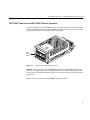

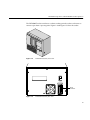


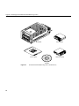
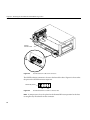
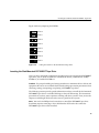

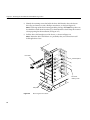
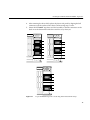


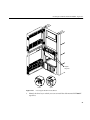

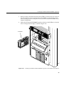

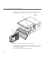


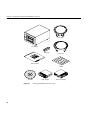
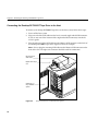
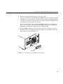
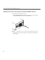


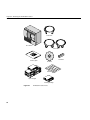
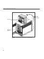

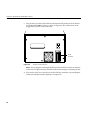
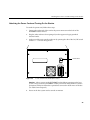

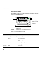
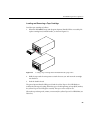
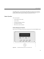

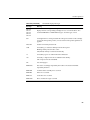
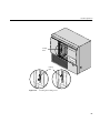
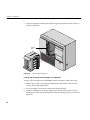
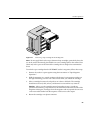

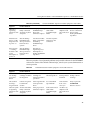

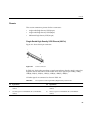
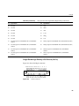
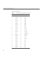
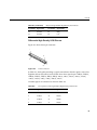
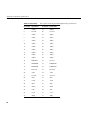


![X-Fire installation instructions - A [IT]](http://vs1.manualzilla.com/store/data/006135060_1-2af8b96d0bc67f8efa4fc02ccbd730a8-150x150.png)