1
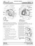
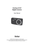
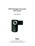
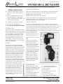
edia
oan
Operating Guide for
Vivitar 283 & 285 flashes
Media Loan Operating Guides are also available online at www.evergreen.edu/media/ml/
General Precautions
MODES OF OPERATION
N Care must be taken as burns
can occur from touching hot
parts.
There are multiple methods for taking pictures with these flashes: Using the automatic exposure control, using partial power or
determining the flash manually. N Do not operate flash if it has
been dropped or damaged
until it has been examined by a
Media Loan assistant.
Setting focal length on the 285
N Let flash cool before storing.
Calculator Dial
N Do not get the flash wet.
On the end of the flash hinge is the calculator (calc.) dial with
three concentric inner rings, and one outside. The calculator dial
is not connected to the flash and does not control functions. It is a
tool to help you find the correct aperture setting for your camera
based on distance from your subject, ASA of your film, or flash
power setting (285 only). You will want the camera's shutter speed
set to recommended
settings. Media Loan's
cameras should be set to
1/60 of a second, or "x".
N Do not use with digital cameras.
Powering on
The power switch on the back of the
flash should show red for the power to
be ON. The flash will emit a high pitch
as it is charging, and when it is ready,
the Open Flash control lights. If the
Open Flash push-button blinks, this is
indicating a battery-saving circuit is
in operation. If the button does not
light within 30 seconds, your batteries
should be replaced.
POWER
When using different focal lengths with the 285 you can adjust
between wide (35), norm (50/55) and tele (105). 28mm wide
inserts and diffusers are also available.
Using the Dial on the
283
Select your film speed
(ASA) by turning the dial
until the black arrow
lines up with your desired
setting. Either estimate
or measure the distance
from the flash to the
subject being illuminated. In the colored section go
to the distance in either
feet (ft) or meters (m).
Set the thyristor (sensor
unit on the front of the
flash) to the color shown
and your camera to the
number given in f-stops
above that color.
The flash uses four (4) AA batteries
which fit into a holder in the battery
compartment, next to the swivel head
hinge, or with an optional AC power
adapter the flash can be plugged into
a standard wall outlet for power (this
adapter is available through Media
Loan). To insert the batteries, rotate
the head to the 0 degree position,
and slide the battery compartment
door toward the rear of the body.
Do not try to completely remove the
compartment door. It stays attached
to the flash unit. The holder may now
be removed. Align the +/- ends
as indicated on the holder body. 1. Open Flash Button
Use alkaline batteries, others may
2. Thyristor (Sensor Socket)
be cheaper, but they will not last
3. Battery Compartment Cover
as long and may not function
4. Illuminated Calculator Dial
properly. Insert so the bare ends
5. ASA/DIN Indicator Arrow
of the cells enter first. Press the
6. Lens/Filter Slot
holder into the cavity, and hold it
7. Zoom/Bounce Flash Head
down against the spring pressure
8. Zoom Setting Indicator
as shut the cover.
9. Bounce Angle Scale
Media Loan
360.867.6253
¸ Please Recycle!
10. Sufficient Light Indicator
11. Calculator Dial Light Button
12. On-Off Switch
13. Ready Light
14. Mounting Foot Lock Lever
15. Mounting Foot
16. Shutter Cord Socket
17. AC Adapter Receptacle
The Evergreen State College
Olympia, WA 98505
vivitarflash | 03.10.08 | JW
Media Loan
Vivitar 283 & 285 Flashes
Using the dial on the 285
Thyristor (Sensor socket) Settings
If using an automatic mode:
Select your film speed (ASA) by
rotating the outside ring. Make
sure the next ring has the black
arrow pointing at FULL. Now using
the distance from flash to subject
find the distance on the inner
most ring, again in either feet (ft)
or meters (m). Using the color that
covers your distance range, set the
thyristor, and your camera using
the f-stops given just above the
distance and color indicators.
M - Manual, the maximum amount of light will be output in this
setting at all times. When in manual mode you can determine
F-stop using the calculator dial, but disregard the color bands.
Yellow - The widest lens opening for shallowest depth of field. This
will allow the greatest depth of flash
illumination while in an automatic mode, from 5 to 43 feet.
Red - A medium lens opening for greater depth of field, but shorter
operating distance, from 4 to 30 feet.
Blue - Greater still depth of field, shorter depth of illumination, 2 to
15 feet.
Purple - Maximum depth of field, smallest aperture and minimum
range of illumination, 2 to 11 feet.
Sufficient Light Indicator
i If using partial power settings: Select how
much power you wish to use by adjusting the
dial on the thyristor (1/16, 1/4, or 1/2). Select
your film speed (ASA) with the outermost
ring, and what power you wish to use with
the next ring in. As with the auto modes,
find your distance and set your f-stops
accordingly.
The SLI will slow for 2-3 seconds after a flash if the
sensor reads the correct light level during the
illumination. You can check your exposure before
taking a shot by manually triggering the flash unit
and watching the SLI. If it doesn't light, you can
do a number of things to correct the illumination. Set the Mode Selector to a value which will allow
a wider f-stop and reduce the subject and flash
distance; bounce the light from a more reflective
surface.
Auto Exposure Control
On the front of the flash is the Auto Thyristor Sensor. This small device detects the amount of light present
when the flash is triggered, metering the level of
illumination on the subject. The outer collar of the
sensor is the mode selector. This rotates to set for
different aperture ranges while in the automatic
mode, or to set for manual operation. Holding
the unit upright and pointed to the right, the small
window on the side of the sensor shows the ranges in
different colors, flash power or M for manual.
i The SLI will not work in manual mode.
Flash Guide Numbers
Flash guide numbers will help you calculate f-stops
for exposures using the manual position or when you
bounce your illumination.
Measure the flash-reflector-subject distance, and
divide the total into the Flash Guide number listed
for the ASA film you are using. Round off the result to
the nearest f-stop and open one stop wider.
Example: using ASA 25 film with a camera-reflector
subject-distance of 20 feet -- Guide #20 divided by
20 equals 3 (f2.8 approximate) open an additional
stop to f2.
You can estimate flash bounce settings in other
ways. In average rooms, a general rule is to open
two stops from where you would set a direct shot.
OR, using the Calculator Dial, estimate the camerareflector-subject distance and open one more stop
from what is indicated on the dial.
Bounce Lighting
In situations where reflective surfaces are above
your subject, you can "bounce" the light from the
flash unit off the ceiling to diffuse the illumination. This will reduce shadows and soften the glare
normally associated with flash photos. When using
bounce techniques, be sure to calculate the flash
to reflective surface to subject distance when
setting the f-stop. The reflective surface's light
absorption characteristics will affect the amount of
illumination that gets to the subject. The color will
also be transmitted to the subject, so choose neutral
colored surfaces. When bouncing off absorbent
surfaces, open the calculated f-stop one additional
stop.
GUIDE NUMBERS:
ASA
Guide # 60
25
96
64
108
80
120
100
135
125
150
160
170
200
240
400
340
800