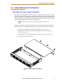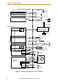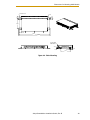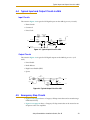
1
Adept SmartMotion Installation Guide F2 DE2 F6 DE6 F1 DE1 F5 DE5 ES HPE F4 DE4 STATUS F3 DE3 XENCODER XMACHINE XSERVO XANL XDC1 XDC2 24V 0.5A -+ s MI6 *S/N 3564-XXXXX* SmartServo 1.1 1.2 R -+ *S/N 3561-XXXXX* SmartServo OK SF HPE ES LAN HD SW1 1.1 Device Net 1.2 Eth 10/100 RS-232/TERM RS-422/485 1 2 3 4 ON OFF 1 2 3 XDIO XUSR XSYS XFP XMCP XDC1 XDC2 24V 5A -+ -+ Adept SmartController CS with sMI6 Motion Interface Module SmartController CS R Adept SmartMotion Installation Guide F2 DE2 F6 DE6 F1 DE1 F5 DE5 ES HPE F4 DE4 STATUS F3 DE3 XENCODER XMACHINE XSERVO XANL XDC1 XDC2 24V 0.5A -+ s MI6 *S/N 3564-XXXXX* SmartServo 1.1 1.2 R -+ *S/N 3561-XXXXX* SmartServo OK SF HPE ES LAN HD SW1 1.1 Device Net 1.2 Eth 10/100 RS-232/TERM RS-422/485 1 2 3 4 ON OFF 1 2 3 XDIO XUSR XSYS XFP XMCP XDC1 XDC2 24V 5A -+ -+ Adept SmartController CS with sMI6 Motion Interface Module 02170-000, Rev B April, 2003 3011 Triad Drive • Livermore, CA 94550 • USA • Phone 925.245.3400 • Fax 925.960.0452 Otto-Hahn-Strasse 23 • 44227 Dortmund • Germany • Phone 49.231.75.89.40 • Fax 49.231.75.89.450 41, rue du Saule Trapu • 91300 • Massy • France • Phone 33.1.69.19.16.16 • Fax 33.1.69.32.04.62 SmartController CS R The information contained herein is the property of Adept Technology, Inc., and shall not be reproduced in whole or in part without prior written approval of Adept Technology, Inc. The information herein is subject to change without notice and should not be construed as a commitment by Adept Technology, Inc. This manual is periodically reviewed and revised. Adept Technology, Inc., assumes no responsibility for any errors or omissions in this document. Critical evaluation of this manual by the user is welcomed. Your comments assist us in preparation of future documentation. Please email your comments to: [email protected]. Copyright 2003 by Adept Technology, Inc. All rights reserved. The Adept logo, CHAD, the CHAD logo, and Soft Machines are registered trademarks of Adept Technology, Inc. ActiveV, Adept, Adept 1060, Adept 1060+, Adept 1850, Adept 1850 XP, Adept 540, Adept 560, Adept C40, Adept C60, Adept CC, Adept CHADIQ, Adept CHADIQh, Adept CHADIQt, Adept Cobra 550, Adept Cobra 550 CleanRoom, Adept Cobra 600, Adept Cobra 800, Adept DeskTop, Adept Digital Workcell, Adept FFE, Adept FlexFeeder 250, Adept IC, Adept Impulse Feeder, Adept LineVision, Adept MC, Adept MV, Adept MV-10, Adept MV-19, Adept MV4, Adept MV-5, Adept MV-8, Adept NanoBonder EBS, Adept NanoBonder LWS, Adept NanoCell, Adept NanoStage L1P2, Adept NanoStage L3, Adept NanoStage L3P2, Adept OC, Adept SmartAmp, Adept SmartAxis, Adept SmartController CS, Adept SmartController CX, Adept SmartModule, Adept SmartMotion, Adept SMIF-EZ, AdeptAlign 650, AdeptAtlas, AdeptCartesian, AdeptForce, AdeptFTP, AdeptGEM, AdeptModules, AdeptMotion, AdeptMotion Servo, AdeptMotion VME, AdeptNet, AdeptNFS, AdeptOne, AdeptOne-MV, AdeptOne-XL, AdeptRAPID, AdeptSix 300, AdeptSix 300CL, AdeptTCP/IP, AdeptThree, AdeptThree-MV, AdeptThree-XL, AdeptTwo, AdeptVicron, AdeptVicron 300S, AdeptVicron 310D, AdeptVision, AdeptVision AVI, AdeptVision AGS, AdeptVision GV, AdeptVision I, AdeptVision II, AdeptVision VME, AdeptVision VXL, AdeptVision XGS, AdeptVision XGS II, AdeptWindows , AdeptWindows Controller, AdeptWindows DDE, AdeptWindows Offline Editor, AdeptWindows PC, AIM, AIM Command Server, AIM Dispense, AIM PCB, AIM VisionWare, A-Series, AutoCal, AutoTune, AutoWidth, CCM, CCMII, CGM, CHAD ACM, CHAD ACT, CHAD AF, CHAD AutoClinchMaster, CHAD BLT, CHAD CH, CHAD ClinchMaster, CHAD ClinchMaster II, CHAD CS, CHAD CSII, CHAD ECA, CHAD GuideMaster, CHAD HT, CHAD LGM, CHAD LLG, CHAD MGE, CHAD MixTech, CHAD MTM, CHAD OFM, CHAD PIE, CHAD QCB, CHAD RC, CHAD SGE, CHAD TM, CHAD VT, CimStation, CimStation Robotics, FlexFeedWare, HexSight, HyperDrive, Microenvironment, MicroV+, MotionWare, ObjectFinder, ObjectFinder 2000, PackOne, PalletWare, Production PILOT, SILMA CellFLEX, SILMA CellPRO, SILMA PaintPRO, SILMA PressPRO, SILMA SpotPRO, SMIF-C, SMIF-EZX, SMIF-Z, SMIF-ZX, SoftAssembly, S-Series, UltraOne, V, V+, and VisionTeach are trademarks of Adept Technology, Inc. Any trademarks from other companies used in this publication are the property of those respective companies. Printed in the United States of America Table of Contents 1 Introduction . . . . . . . . . . . . . . . . . . . . . . . . . . . . . . . . . . . . . . . . . . . . . . . 11 1.1 Product Description. . . . . . . . . . . . . . . . . . . . . . . . . . . . . . . . . . . . . . . . . . . . . . . . 11 System Overview . . . . . . . . . . . . . . . . . . . . . . . . . . . . . . . . . . . . . . . . . . . . . . . Adept SmartMotion Hardware Overview . . . . . . . . . . . . . . . . . . . . . . . . . . Adept sMI6 Motion Interface Module . . . . . . . . . . . . . . . . . . . . . . . Motion Interface Kit . . . . . . . . . . . . . . . . . . . . . . . . . . . . . . . . . . . . . . 11 11 12 12 1.2 Safety . . . . . . . . . . . . . . . . . . . . . . . . . . . . . . . . . . . . . . . . . . . . . . . . . . . . . . . . . . . 12 Reading and Training for Users and Operators . . . . . . . . . . . . . . . . . . . . . . System Safeguards. . . . . . . . . . . . . . . . . . . . . . . . . . . . . . . . . . . . . . . . . . . . . . Safety Features on Front Panel . . . . . . . . . . . . . . . . . . . . . . . . . . . . . Computer Controlled Robots and Motion Devices . . . . . . . . . . . . Manually Controlled Robots and Motion Devices . . . . . . . . . . . . . Other Computer Controlled Devices . . . . . . . . . . . . . . . . . . . . . . . . Program Security . . . . . . . . . . . . . . . . . . . . . . . . . . . . . . . . . . . . . . . . . . . . . . . Overspeed Protection . . . . . . . . . . . . . . . . . . . . . . . . . . . . . . . . . . . . . . . . . . . Voltage Interruptions . . . . . . . . . . . . . . . . . . . . . . . . . . . . . . . . . . . . . . . . . . . . Inappropriate Uses of the Adept SmartController . . . . . . . . . . . . . . . . . . . . 12 13 13 13 13 13 14 14 14 14 1.3 Warnings, Cautions, and Notes . . . . . . . . . . . . . . . . . . . . . . . . . . . . . . . . . . . . . . 15 1.4 How Can I Get Help? . . . . . . . . . . . . . . . . . . . . . . . . . . . . . . . . . . . . . . . . . . . . . . 16 1.5 Related Manuals . . . . . . . . . . . . . . . . . . . . . . . . . . . . . . . . . . . . . . . . . . . . . . . . . . 16 2 System Installation . . . . . . . . . . . . . . . . . . . . . . . . . . . . . . . . . . . . . . . . . . 17 2.1 Overview of Installation Process . . . . . . . . . . . . . . . . . . . . . . . . . . . . . . . . . . . . . 17 2.2 Adept sMI6 Connectors and Indicators . . . . . . . . . . . . . . . . . . . . . . . . . . . . . . . 18 Adept sMI6 LED Descriptions . . . . . . . . . . . . . . . . . . . . . . . . . . . . . . . . . . . . . 18 Adept sMI6 Connectors . . . . . . . . . . . . . . . . . . . . . . . . . . . . . . . . . . . . . . . . . 19 2.3 System Cable Diagram . . . . . . . . . . . . . . . . . . . . . . . . . . . . . . . . . . . . . . . . . . . . 20 2.4 Adept sMI6 Hardware Configuration . . . . . . . . . . . . . . . . . . . . . . . . . . . . . . . . . 21 sMI6 Digital Input Logic Voltage Configuration . . . . . . . . . . . . . . . . . . . . . . 21 2.5 Proper Wiring and Electrical Design Practices . . . . . . . . . . . . . . . . . . . . . . . . . . 23 2.6 Enclosure for SmartController and sMI6 . . . . . . . . . . . . . . . . . . . . . . . . . . . . . . . 24 2.7 Installing the Adept SmartController . . . . . . . . . . . . . . . . . . . . . . . . . . . . . . . . . 25 2.8 Installing the Adept sMI6 Module . . . . . . . . . . . . . . . . . . . . . . . . . . . . . . . . . . . . 25 2.9 Installing MP6 Panels . . . . . . . . . . . . . . . . . . . . . . . . . . . . . . . . . . . . . . . . . . . . . . 26 Rail Mounting the MP6 Panels . . . . . . . . . . . . . . . . . . . . . . . . . . . . . . . . . . . . 26 Panel Mounting the MP6 Panels . . . . . . . . . . . . . . . . . . . . . . . . . . . . . . . . . . 27 Plug-In Opto Modules on the MP6-M . . . . . . . . . . . . . . . . . . . . . . . . . . . . . . 27 Adept SmartMotion Installation Guide, Rev. B 5 Table of Contents 2.10 MP6 Machine (MP6-M) Panel Wiring . . . . . . . . . . . . . . . . . . . . . . . . . . . . . . . . . 31 Optical Isolation . . . . . . . . . . . . . . . . . . . . . . . . . . . . . . . . . . . . . . . . . . . . . . . . 31 Input Current Requirements (OT, HM) . . . . . . . . . . . . . . . . . . . . . . . . 31 Input Voltage Configuration . . . . . . . . . . . . . . . . . . . . . . . . . . . . . . . 32 Output Current Requirements (MP6-M, HPE and BR, External). . . . 32 User-Supplied Logic Power (Internal). . . . . . . . . . . . . . . . . . . . . . . . . 32 Overtravel Limit Switches (Input) . . . . . . . . . . . . . . . . . . . . . . . . . . . . . . . . . . . 33 Home Switch (Input) . . . . . . . . . . . . . . . . . . . . . . . . . . . . . . . . . . . . . . . . . . . . . 33 Brake Release (Output) . . . . . . . . . . . . . . . . . . . . . . . . . . . . . . . . . . . . . . . . . . 33 High Power Enable (Output) . . . . . . . . . . . . . . . . . . . . . . . . . . . . . . . . . . . . . . 33 2.11 MP6 Servo (MP6-S) Panel Wiring. . . . . . . . . . . . . . . . . . . . . . . . . . . . . . . . . . . . . 35 Drive Compatibility . . . . . . . . . . . . . . . . . . . . . . . . . . . . . . . . . . . . . . . . . . . . . 35 Optical Isolation . . . . . . . . . . . . . . . . . . . . . . . . . . . . . . . . . . . . . . . . . . . . . . . . 35 MP6-S Input Current Requirements (Drive Fault) . . . . . . . . . . . . . . . 35 MP6-S Output Current Requirements (Drive Enable) . . . . . . . . . . . . 35 Connecting the Drives . . . . . . . . . . . . . . . . . . . . . . . . . . . . . . . . . . . . . . . . . . . 36 Drive Enable (Output) . . . . . . . . . . . . . . . . . . . . . . . . . . . . . . . . . . . . . . . . . . . 37 Delay Time . . . . . . . . . . . . . . . . . . . . . . . . . . . . . . . . . . . . . . . . . . . . . . 37 Drive Fault (Input) . . . . . . . . . . . . . . . . . . . . . . . . . . . . . . . . . . . . . . . . . . . . . . . 37 Command Drive (Output) . . . . . . . . . . . . . . . . . . . . . . . . . . . . . . . . . . . . . . . . 37 2.12 MP6 Encoder (MP6-E) Panel Wiring . . . . . . . . . . . . . . . . . . . . . . . . . . . . . . . . . . 38 Encoder Compatibility . . . . . . . . . . . . . . . . . . . . . . . . . . . . . . . . . . . . . . . . . . . 38 Connecting Power to the Encoders . . . . . . . . . . . . . . . . . . . . . . . . . . . . . . . 38 Encoder Power Grounding . . . . . . . . . . . . . . . . . . . . . . . . . . . . . . . . . . . . . . . 39 Encoder Cable Length (User Supplied) . . . . . . . . . . . . . . . . . . . . . . . . . . . . . 39 Connecting the Encoders . . . . . . . . . . . . . . . . . . . . . . . . . . . . . . . . . . . . . . . . 40 Encoder Input Circuitry . . . . . . . . . . . . . . . . . . . . . . . . . . . . . . . . . . . . . . . . . . 40 Single-Ended Encoders . . . . . . . . . . . . . . . . . . . . . . . . . . . . . . . . . . . . . . . . . . 42 3 Software Configuration . . . . . . . . . . . . . . . . . . . . . . . . . . . . . . . . . . . . . . 43 3.1 Introduction . . . . . . . . . . . . . . . . . . . . . . . . . . . . . . . . . . . . . . . . . . . . . . . . . . . . . . 43 3.2 Phase 1 - Preparation for Software Configuration. . . . . . . . . . . . . . . . . . . . . . . . 44 3.3 Phase 2 - Load Device Modules. . . . . . . . . . . . . . . . . . . . . . . . . . . . . . . . . . . . . . 44 3.4 Phase 3 - Configure SmartServo Network Map. . . . . . . . . . . . . . . . . . . . . . . . . . 44 3.5 Phase 4 - Create Software Specification . . . . . . . . . . . . . . . . . . . . . . . . . . . . . . 44 3.6 Phase 5 - Testing the System. . . . . . . . . . . . . . . . . . . . . . . . . . . . . . . . . . . . . . . . . 45 3.7 Motion Control Application Development . . . . . . . . . . . . . . . . . . . . . . . . . . . . . 45 4 Technical Specifications . . . . . . . . . . . . . . . . . . . . . . . . . . . . . . . . . . . . . 47 4.1 Dimensions for sMI6 Module . . . . . . . . . . . . . . . . . . . . . . . . . . . . . . . . . . . . . . . . 47 4.2 Dimensions for Mounting sMI6 Module . . . . . . . . . . . . . . . . . . . . . . . . . . . . . . . . 48 4.3 MP6 to sMI6 Cables 6 . . . . . . . . . . . . . . . . . . . . . . . . . . . . . . . . . . . . . . . . . . . . . . . 50 Adept SmartMotion Installation Guide, Rev. B Table of Contents 4.4 Typical Input and Output Circuits in sMI6 . . . . . . . . . . . . . . . . . . . . . . . . . . . . . . 53 Input Circuits . . . . . . . . . . . . . . . . . . . . . . . . . . . . . . . . . . . . . . . . . . . . . . . . . . 53 Output Circuits . . . . . . . . . . . . . . . . . . . . . . . . . . . . . . . . . . . . . . . . . . . . . . . . 53 4.5 Emergency Stop Circuits . . . . . . . . . . . . . . . . . . . . . . . . . . . . . . . . . . . . . . . . . . . 53 Index . . . . . . . . . . . . . . . . . . . . . . . . . . . . . . . . . . . . . . . . . . . . . . . . . . . . . . . . 57 Adept SmartMotion Installation Guide, Rev. B 7 List of Figures Figure 1-1. Adept sMI6 Module . . . . . . . . . . . . . . . . . . . . . . . . . . . . . . . . . . . . . . . . . . . . . . 11 Figure 2-1. Close-up of sMI6 LED Labels . . . . . . . . . . . . . . . . . . . . . . . . . . . . . . . . . . . . . . . 18 Figure 2-2. Adept sMI6 Module Front Panel . . . . . . . . . . . . . . . . . . . . . . . . . . . . . . . . . . . 19 Figure 2-3. Adept SmartMotion System Cable Diagram . . . . . . . . . . . . . . . . . . . . . . . . . 20 Figure 2-4. Opening the sMI6 Chassis . . . . . . . . . . . . . . . . . . . . . . . . . . . . . . . . . . . . . . . . 21 Figure 2-5. Location of Jumpers on Main PCA . . . . . . . . . . . . . . . . . . . . . . . . . . . . . . . . . 22 Figure 2-6. MP6-S Panel – Layout and Dimensions Figure 2-7. MP6-E Panel – Layout and Dimensions . . . . . . . . . . . . . . . . . . . . . . . . . . . . . 28 Figure 2-8. MP6-M Panel – Layout and Dimensions . . . . . . . . . . . . . . . . . . . . . . . . . . . . . 29 Figure 2-9. Typical System Wiring for One Axis of Motion . . . . . . . . . . . . . . . . . . . . . . . . 30 Figure 2-10. Encoder Input Circuitry . . . . . . . . . . . . . . . . . . . . . . . . . . . . . . . . . . . . . . . . . . . 41 Figure 2-11. Encoder Input Schematic . . . . . . . . . . . . . . . . . . . . . . . . . . . . . . . . . . . . . . . . 41 Figure 2-12. Single-Ended Encoder Wiring Using Inverted Outputs . . . . . . . . . . . . . . . . . 42 Figure 2-13. Single-Ended Encoder Wiring Using Non-Inverted Outputs . . . . . . . . . . . . . 42 . . . . . . . . . . . . . . . . . . . . . . . . . . . . . 28 Figure 3-1. SmartMotion System Installed to Control a User Mechanism . . . . . . . . . . . . 43 Figure 4-1. Dimensions for sMI6 Module . . . . . . . . . . . . . . . . . . . . . . . . . . . . . . . . . . . . . . . 47 Figure 4-2. Rack Mounting . . . . . . . . . . . . . . . . . . . . . . . . . . . . . . . . . . . . . . . . . . . . . . . . . 48 Figure 4-3. Panel Mounting . . . . . . . . . . . . . . . . . . . . . . . . . . . . . . . . . . . . . . . . . . . . . . . . . 48 Figure 4-4. Table Mounting . . . . . . . . . . . . . . . . . . . . . . . . . . . . . . . . . . . . . . . . . . . . . . . . . 49 Figure 4-5. Typical Input Circuit in sMI6 . . . . . . . . . . . . . . . . . . . . . . . . . . . . . . . . . . . . . . . 53 Figure 4-6. Typical Output Circuit in sMI6 . . . . . . . . . . . . . . . . . . . . . . . . . . . . . . . . . . . . . 53 Figure 4-7. Category 3 E-Stop Circuit . . . . . . . . . . . . . . . . . . . . . . . . . . . . . . . . . . . . . . . . 54 Figure 4-8. Category 1 E-Stop Circuit . . . . . . . . . . . . . . . . . . . . . . . . . . . . . . . . . . . . . . . . 55 Adept SmartMotion Installation Guide, Rev B 9 Introduction 1.1 1 Product Description The Adept SmartMotion product consists of a hardware and software package that provides high-performance coordinated motion control for industrial automation devices. Adept SmartMotion includes the sMI6 motion interface module and the Adept SmartController, communicating via the SmartServo network, Adept’s distributed controls network built on IEEE 1394. Completely integrated V+ software provides the same high-level motion instructions that are used for Adept robots. The sMI6 supports up to six axes of motion control per module. F2 DE2 F6 DE6 F1 DE1 F5 DE5 ES HPE F4 DE4 STATUS F3 DE3 XENCODER XMACHINE XSERVO XANL s MI6 *S/N 3564-XXXXX* SmartServo 1.1 1.2 R XDC1 XDC2 24V -+ 0.5A -+ Figure 1-1. Adept sMI6 Module System Overview Adept SmartMotion has been designed to function as an integral part of Adept’s control system. Typical components include an Adept SmartController (CS or CX model), one or more sMI6 modules, MP6 panels, a manual control pendant, a desktop or laptop PC, and a user-supplied mechanism with servomotors, encoders, and amplifiers. Additional options such as Adept-supplied robots and vision systems are available. Adept SmartMotion is intended to provide complete motion control of user-supplied mechanisms. Users retain the flexibility of selecting the drive components that are best suited for their applications. Adept SmartMotion can interface to industry standard drive components including most servo amplifiers and optical encoders. Motion-related I/O signals can utilize voltage levels chosen by the user. Adept SmartMotion Hardware Overview There are two major hardware components of the system, in addition to the SmartController: • Adept sMI6 Motion Interface Module • Motion Interface Kit, includes MP6 panels and interface cables (this kit is optional) Adept SmartMotion Installation Guide, Rev. B 11 Chapter 1 - Introduction Adept sMI6 Motion Interface Module The Adept sMI6 Motion Interface module is a six-channel unit that runs the Adept SmartMotion product. The sMI6 module is a stand-alone unit designed to control a total of six motion axes or external encoders. Each sMI6 module has six servo drive outputs, six incremental encoder inputs, and digital I/O for machine and amplifier control. Motion Interface Kit The Motion Interface Kit includes the three Motion-interface Panels (MP6-E, MP6-M, and MP6-S) that serve as the interface between the sMI6 module and the user’s hardware. The MP6 panels provide mounting sockets for I/O modules used in conjunction with the dedicated discrete input/output signals. The MP6 panels also provide detachable barrier-type screw terminal strips and 9-Pin D connectors for all field wiring terminations. Interface cables (3 meter) for connecting the sMI6 to the MP6 panels are included in the kit. NOTE: The Motion Interface Kit is optional, but it is recommended for typical installations. Customers who do not order this option must provide similar functionality. 1.2 Safety WARNING: See the Adept SmartController User’s Guide for additional safety information. Reading and Training for Users and Operators Adept systems can include computer-controlled mechanisms that are capable of moving at high speeds and exerting considerable force. Like all robot and motion systems, and most industrial equipment, they must be treated with respect by the user and the operator. This manual should be read by all personnel who operate or maintain Adept systems, or who work within or near the workcell. We recommend you read the American National Standard for Industrial Robot Systems - Safety Requirements, published by the Robotic Industries Association (RIA), in conjunction with the American National Standards Institute. The publication, ANSI/RIA R15.06 - 1992, contains guidelines for robot system installation, safeguarding, maintenance, testing, start-up, and operator training. We also recommend you read the European Standard EN 60204, Safety of Machinery – Electrical Equipment of Machines, particularly if the country of use requires a CE-certified installation. (See the Adept SmartController User’s Guide for ordering information for national and international standards.) This manual assumes that the user has attended an Adept training course, or at least has a basic working knowledge of the system. The user should provide the necessary additional training for all personnel who will be working with the system. 12 Adept SmartMotion Installation Guide, Rev. B Safety There are several warnings in this manual that say only skilled or instructed persons should attempt certain procedures. These are defined as: • Skilled persons have technical knowledge or sufficient experience to enable them to avoid the dangers which electricity may create (engineers and technicians). • Instructed persons are adequately advised or supervised by skilled persons to enable them to avoid the dangers which electricity may create (operating and maintenance staff). System Safeguards Safeguards should be an integral part of robot or motion workcell design, installation, operator training, and operating procedures. Adept systems have various communication features to aid in constructing system safeguards. These include the emergency stop circuitry and digital input and output lines. Some of these features are described in the Adept SmartController User’s Guide. Safety Features on Front Panel The optional Front Panel has important safety features, including the HIGH POWER indicator, the AUTO/MANUAL keyswitch, and the EMERGENCY STOP switch. If you choose not to use the Front Panel, you should provide similar safety features by using the connectors on the SmartController. Refer to the Adept SmartController User’s Guide for more information. WARNING: Entering the workcell when the HIGH POWER light is on can result in severe injury. This warning applies to each of the next three sections. Computer Controlled Robots and Motion Devices Adept systems are computer controlled, and the program that is currently running the robot or motion device may cause it to move at times or along paths you may not anticipate. When the HIGH POWER light is illuminated, do not enter the workcell because the robot or motion device might move unexpectedly. Manually Controlled Robots and Motion Devices Adept robots and other motion devices can also be controlled manually when the HIGH POWER light on the Front Panel is illuminated. When this light is lit, motion can be initiated from the system keyboard or from the optional Manual Control Pendant (MCP). If you have to enter the workcell when this light is lit, press the MAN/HALT button on the MCP. This will prevent anyone else from initiating unexpected motion from the system keyboard. Other Computer Controlled Devices In addition, Adept systems can be programmed to control equipment or devices other than the robot or main motion device. The program controlling these other devices may cause them to operate unexpectedly. Make sure that safeguards are in place to prevent personnel from entering the workcell when a program is running. Adept SmartMotion Installation Guide, Rev. B 13 Chapter 1 - Introduction Adept Technology highly recommends the use of additional safety features such as light curtains, safety gates, or safety floor mats to prevent entry to the workcell while HIGH POWER is enabled. These devices can be connected using the emergency stop circuitry. Program Security Programs and data stored in memory can be changed by trained personnel using the V+ commands and instructions documented in the V+ manuals. To prevent unauthorized alteration of programs, you should restrict access to the keyboard. This can be done by placing the keyboard in a locked cabinet. Alternatively, the V+ ATTACH instruction can be used in your programs to restrict access to the V+ command prompt. Overspeed Protection Overspeed protection for a robot or motion system has to be taken into account during system integration by the integrator or end-user. Overspeed protection is not guaranteed by the controller hardware alone. The V+ system software offers some overspeed protection capabilities. Voltage Interruptions If the power supply to the controller is interrupted, the passive E-stop output will be automatically turned on (opened). In addition, the High Power, Brake Release, and Drive Enable signals will be turned off. You must ensure that these signals are used to prevent a hazardous condition. Inappropriate Uses of the Adept SmartController The Adept SmartController is intended for use as a component sub-assembly of a complete industrial automation system. The SmartController sub-assembly must be installed inside a suitable enclosure. Installation and usage must comply with all safety instructions and warnings in this manual. Installation and usage must also comply with all applicable local or national statutory requirements and safety standards.The SmartController sub-assembly is not intended for use in any of the following situations: • In hazardous (explosive) atmospheres • In mobile, portable, marine, or aircraft systems • In residential installations • In situations where the SmartController sub-assembly may come into contact with liquids. • In situations where the SmartController sub-assembly will be subject to extremes of heat or humidity. See the specifications for allowable temperature and humidity ranges. See the Adept SmartController User’s Guide for any additional restrictions. 14 Adept SmartMotion Installation Guide, Rev. B Warnings, Cautions, and Notes 1.3 Warnings, Cautions, and Notes There are four levels of special alert notation used in this manual. In descending order of importance, they are: DANGER: This indicates an imminently hazardous situation which, if not avoided, will result in death or serious injury. WARNING: This indicates a potentially hazardous situation which, if not avoided, could result in serious injury or major damage to the equipment. CAUTION: This indicates a situation which, if not avoided, could result in minor injury or damage to the equipment. NOTE: This provides supplementary information, emphasizes a point or procedure, or gives a tip for easier operation. Adept SmartMotion Installation Guide, Rev. B 15 Chapter 1 - Introduction 1.4 How Can I Get Help? Refer to the How to Get Help Resource Guide (Adept P/N 00961-00700) for details on getting assistance with your Adept software and hardware. This document is available on the Adept Documentation Library CD-ROM that is shipped with all systems. Additionally, you can access information sources on Adept’s corporate Web site: http://www.adept.com 1.5 Related Manuals This manual covers the installation of an Adept SmartMotion system. There are additional manuals that cover software configuration, programming the system, reconfiguring installed components, and adding other optional components. Refer to the following manuals for additional information your Adept system. NOTE: Al l of the manuals in Table 1-1 are available on the Adept Documentation Library CD-ROM provided with each system. (Previously this was known as the Knowledge Express CD-ROM.) Table 1-1. Related Manuals Manual Title Description Describes the software configuration process for the Adept SmartMotion product. See Chapter 3 for more information. Adept SmartMotion Developer’s Guide The Adept SmartMotion Developer’s Guide is provided as an online HTML document with a Table of Contents, Search, and Index features to navigate the document. If you do not see these features when you are viewing a topic, click the SHOW TOC icon that displays in the upper left corner of each page. Adept SmartController User’s Guide Contains complete information on the installation and operation of the Adept SmartController and the optional sDIO product. AdeptWindows Installation Guide and AdeptWindows Online Help Describes complex network installations, installation and use of NFS server software, and the AdeptWindows DDE software. Instructions for Adept Utility Programs Describes the utility programs used for advanced system configurations, system upgrades, file copying, and other system configuration procedures. V+ Operating System User’s Guide Describes the V+ operating system, including disk file operations, monitor commands, and monitor command programs. V+ Language User’s Guide Describes the V+ language and programming of an Adept control system. 16 Adept SmartMotion Installation Guide, Rev. B System Installation 2.1 2 Overview of Installation Process This section provides a summary of the major steps involved with installing a Adept SmartMotion system. 1. Verify that the default hardware configuration for the sMI6 module is correct for your application. The area to look at is: • Digital Input Logic Voltage - see page 21. If you need to change these settings, you will have to open the chassis and install or move jumpers. 2. Review the proper field wiring practices. See Section 2.5 on page 23. 3. Select an enclosure for the SmartController and sMI6 chassis. See Section 2.6 on page 24. NOTE: Refer to the system cable diagram in Figure 2-3 on page 20 for the remaining steps in this process. 4. Install the SmartController and peripherals. See Section 2.7 on page 25. 5. Install the sMI6 module. See Section 2.8 on page 25. 6. Install mounting rails for the three MP6 panels, then mount the three MP6 panels on the rails. See Section 2.9 on page 26. 7. Connect cables from the sMI6 to the MP6-M, MP6-S, and MP6-E panels. 8. Install wiring to user equipment from the MP6-M and MP6-S panels. Also select and install opto-modules. See Section 2.10 on page 31 and Section 2.11 on page 35. 9. Install wiring to user encoders from the MP6-E. See Section 2.12 on page 38. When the above process is complete, the next step is to use the CONFIG_C and SPEC utility programs to configure the software for your system. An overview for this process is located in Chapter 3. Adept SmartMotion Installation Guide, Rev. B 17 Chapter 2 - System Installation 2.2 Adept sMI6 Connectors and Indicators Adept sMI6 LED Descriptions F2 DE2 F6 DE6 F1 DE1 F5 DE5 ES HPE F4 DE4 STATUS F3 DE3 Note: early sMI6 Module LED labels had DF instead of F for fault conditions, and NET instead of STATUS. The functionality is identical for both versions. Figure 2-1. Close-up of sMI6 LED Labels The LEDs on the sMI6 are two-color devices - they can display either green or red. Table 2-1. sMI6 LED Functions LED Name 18 Color Function Description Fx (1-6) Solid Red Indicates a Fault condition exists on channel x (1-6). Possible causes are Drive Fault, Overtravel, quadrature error, or broken wire. DEx (1-6) Solid Green Indicates a Drive Enable signal has been asserted for channel x (1-6). ES Solid Red Indicates an E-Stop signal has been asserted from the sMI6. HPE Solid Green Indicates the High Power Enable signal has been asserted. STATUS Solid Red Boot up or microprocessor problem (set by the sMI6 hardware, other patterns are software generated) Slow Blinking Green Normal operation, high power OFF Fast Blinking Green Normal operation, high power ON Fast Blinking Red An error caused High Power to be disabled. See V+ message for source of error. Fast Blinking Red/Green Triggered by utility for identifying a node on the 1394 network Short blink red, long blink red, off, then repeat If this pattern appears at boot-up, it means the SDRAM has failed and the unit must be returned to Adept. Adept SmartMotion Installation Guide, Rev. B Adept sMI6 Connectors and Indicators F2 DE2 F6 DE6 F1 DE1 F5 DE5 ES HPE F4 DE4 STATUS F3 DE3 XENCODER XMACHINE XSERVO XANL s MI6 *S/N 3564-XXXXX* SmartServo 1.1 1.2 R XDC1 XDC2 24V -+ 0.5A -+ Figure 2-2. Adept sMI6 Module Front Panel Adept sMI6 Connectors 1. SmartServo 1.1 and 1.2 These are SmartServo ports. Port 1.1 or 1.2 connects to the SmartController. The other port can connect to an additional sMI6 module or an optional sDIO. 2. XENCODER connector Connects to the MP6-E Panel to communicate signals to and from encoders. 3. XMACHINE connector Connects to the MP6-M Panel to communicate machine signals, such as overtravel, home, brake release, etc. 4. XSERVO connector Connects to the MP6-S Panel to communicate servo signals, such as drive enable, drive fault, etc. 5. XANL connector Reserved for future use. 6. 24VDC connectors Connects user-supplied 24VDC power from the SmartController to the sMI6 connector. The XDC1 and XDC2 connectors are interchangeable - you can use either one. Adept SmartMotion Installation Guide, Rev. B 19 Chapter 2 - System Installation 2.3 System Cable Diagram 5VDC Power from User-Supplied Power Supply to MP6-E SmartServo 1.1 1.2 DF2 DE2 CHAN6 P1 HIGH POWER ENABLE-HPE OVERTRAVEL BRAKE-BR6 HOME OVERTRAVEL HOME BRAKE-BR5 OVERTRAVEL CHAN3 BRAKE-BR3 HOME CHAN2 HOME BRAKE-BR4 BRAKE-BR2 OVERTRAVEL MP6-S Motion-interface Panel - SERVO (MP6-S) HPE S E R V O DF5 DE5 ES HPE DF4 DE4 STATUS DF3 DE3 CHAN4 CHAN6 SPARE CHAN1 CHAN3 CHAN5 ANALOG PWR *S/N 3564-XXXXX* XENCODER XMACHINE XSERVO XANL XDC1 XDC2 24V DF6 DE6 DF1 DE1 CHAN2 -+ IEEE 1394 Cable 0.5A sMI6 Module s MI6 R OVERTRAVEL CHAN4 CHAN1 ENC PWR LOGIC PWR CHAN1 CHAN3 CHAN5 BRAKE-BR1 M A C H I N E CHAN2 CHAN4 CHAN6 RESVD HOME OVERTRAVEL P1 E N C O D E R HOME P1 CHAN5 MP6-M SPARE MP6-E Motion-interface Panel - ENCODER (MP6-E) -+ SmartController 24VDC Power from Controller (XDC2) to sMI6 (XDC1) *S/N 3561-XXXXX* SmartServo OK SF HPE ES LAN HD SW1 1.1 Device Net 1.2 Eth 10/100 RS-232/TERM RS-422/485 1 2 3 4 ON OFF 2 3 XDIO User-Supplied Ground Wires XSYS XUSR XFP Ethernet (Eth 10/100) to PC Terminator Installed XMCP XDC1 XDC2 24V 5A -+ -+ MCP Adapter Cable Controller (XMCP) to MCP 1 SmartController CS R Controller (XFP) to Front Panel (XFP) STOP R Front Panel - + MCP Desktop or Laptop PC 24VDC Power from User-Supplied Power Supply to Controller (XDC1) 24V 5V User-Supplied Power Supply Figure 2-3. Adept SmartMotion System Cable Diagram 20 Adept SmartMotion Installation Guide, Rev. B Adept sMI6 Hardware Configuration 2.4 Adept sMI6 Hardware Configuration sMI6 Digital Input Logic Voltage Configuration The sMI6 can be configured to operate with either a 5V (min 3.0V, max 5.7V) or a 12/24V (min 8.75V, max 27.5V) logic interface. This affects the Home, Overtravel, and Drive Fault signals. The sMI6 is normally shipped configured for 12V input, and must be reconfigured if you decide to operate at 5V. After you configure the sMI6 voltage option, then you must install the MP6 Machine and Servo panels accordingly. NOTE: Refer to Figure 4-5 on page 53 for a typical input circuit in the sMI6. The input voltage is determined by jumpers on the main printed circuit assembly (PCA) inside the chassis. To reconfigure the sMI6 for 5V logic operation, follow this procedure. 1. Verify that the sMI6 is disconnected from the 24VDC power source. 2. Remove the cover of the chassis by removing three screws at the back of the chassis. See Figure 2-4. 3. Install jumpers for each channel that you are using. See Figure 2-5 on page 22. 4. Reinstall the cover on the chassis. Figure 2-4. Opening the sMI6 Chassis Adept SmartMotion Installation Guide, Rev. B 21 Chapter 2 - System Installation Jumpers for Overtravel signals, channels 1 to 6 Jumpers for Home signals, channels 1 to 6 Jumpers for Drive Fault signals, channels 1 to 6 Digital Input Logic Voltage Configuration No jumper = 12/24 V logic (factory default) Jumper installed = 5 V logic Figure 2-5. Location of Jumpers on Main PCA 22 Adept SmartMotion Installation Guide, Rev. B Proper Wiring and Electrical Design Practices 2.5 Proper Wiring and Electrical Design Practices Designing a high-performance servo system requires attention to electrical design. Adept SmartMotion is designed to respond to high-resolution encoder inputs, up to 32 MHz count rate. Most drive amplifiers, DC power supplies, and brush-type motors are potential sources of high-frequency electrical noise. Other equipment in the workcell can also generate noise. Proper system wiring, and especially grounding, is very important to a successful installation. The function of proper grounding is two-fold: first, to reduce the risk of electrical shock from faults in your high-voltage equipment; and second, to help shield from electro-magnetic and radio frequency interference (EMI and RFI). All connections of Adept SmartMotion signals to user-supplied hardware are made via connectors on the three MP6 panels. For proper operation, you must use good wiring practices. Follow the general guidelines presented below. In addition, observe all applicable local and national safety codes. Be sure to: • Verify that all equipment, including motor drives (amplifiers), the robot mechanism, and the SmartController and sMI6 chassis, are properly grounded. • Ensure that all three MP6 Ground terminals are connected to the user-supplied ground point. • Ensure that the MP6 DIN-mounting rail is connected to the user-supplied ground point. • Use only one ground point (star ground system) and keep all ground wires as short as possible. For best results, use braided ground straps for ground connections. (Braid has lower high-frequency impedance, for a given cross-sectional area.) • Use shielded twisted-pair cable for all encoder connections and analog drive signals, and preferably for all signals. • Use separate cables for every encoder and motor drive. Route digital signals, motor power, and encoder signal cables separately from one another. • Locate noise inducing devices away from the controller and other Adept SmartMotion hardware. • Provide noise-free regulated power for all Adept SmartMotion hardware. • Maintain the integrity of optical isolation by using power sources other than the Adept controller to power all signals from user-supplied equipment. • Size all wire according to recognized electrical standards and applicable codes. • Use proper arc suppression devices on all relay and solenoid coils. • Adept recommends using power line filters to help prevent electrical noise from the drive amplifiers “contaminating” the AC power lines, and vice-versa. Adept SmartMotion Installation Guide, Rev. B 23 Chapter 2 - System Installation 2.6 Enclosure for SmartController and sMI6 The Adept SmartController and the Adept sMI6 module should be installed in a suitable enclosures. All of the equipment can be installed in one enclosure, or the sMI6 and associated components can be placed in a separate enclosure near the user’s equipment; see Note below. Enclosures can be very beneficial in helping protect the controller, sMI6 chassis, and associated peripherals and wiring from noise problems and other hazards that are typical in many industrial settings. NOTE: While the sMI6 and MP6 panels should be installed in an enclosure for protection, they can be installed, along with the third-party servo amplifiers, in a remote location closer to the user’s mechanism. The interface between the SmartController system and the sMI6 module is via the SmartServo network using an IEEE 1394 cable. The enclosure must provide the internal environmental conditions (temperature, humidity, etc.) required by the equipment. The enclosure must also meet all local and national safety codes after the equipment is installed. The Emergency Stop circuitry must be incorporated into the setup of the enclosure. It is a good idea to select an enclosure that is large enough so the three MP6 panels can be installed in the same enclosure as the other equipment. The enclosure is also a good place to install additional user equipment such as power supplies, DIN mounting rails, wiring terminal strips, etc. Make sure to keep low-voltage control signal wiring away from high-voltage wiring to avoid interference and noise problems. 24 Adept SmartMotion Installation Guide, Rev. B Installing the Adept SmartController 2.7 Installing the Adept SmartController Refer to the System Cable Diagram in Figure 2-3 on page 20 and to the Adept SmartController User’s Guide to install the SmartController and related peripherals. A brief summary is presented here. 1. Mount the SmartController in the workcell according to the instructions in the Adept SmartController User’s Guide. 2. Install the Compact Flash. 3. Install the user-supplied ground wire from the ground screw on the side of the controller chassis to ground. 4. Install the user-supplied 24VDC power to the controller. Power must be turned off. 5. Connect the optional Adept Front Panel. 6. Connect the MCP. 7. Connect the user-supplied PC and install the AdeptWindows user interface on the PC. 2.8 Installing the Adept sMI6 Module Refer to the System Cable Diagram in Figure 2-3 on page 20. 1. Mount the sMI6 module in the workcell. The mounting options include rack mounting, panel mounting, and table mounting. See Section 4.2 on page 48 for dimension drawings of the different mounting brackets. You can also stack-mount the sMI6 directly above the SmartController with combining brackets. See the Stacking Components section in the Adept SmartController User’s Guide. The sMI6 has the same dimensions as the sDIO module that is shown there. 2. Connect an IEEE 1394 cable from the SmartController to the sMI6. 3. Connect a user-supplied ground wire from the ground screw on the side of the sMI6 chassis to ground. The ground wire must be less than 3 meters long. 4. Connect a 24VDC cable from the SmartController to the sMI6. The DC power cable must be less than 10 meters long. Adept SmartMotion Installation Guide, Rev. B 25 Chapter 2 - System Installation 2.9 Installing MP6 Panels The three 6-channel Motion-interface Panels (MP6-M, MP6-S, and MP6-E) serve as the interface between the sMI6 module and the user’s hardware. The MP6-M panel also provides mounting sockets for up to seven Opto-22 output modules. Figure 2-6, Figure 2-7, and Figure 2-8 show the layout and dimensions of the MP6 panels. Figure 2-9 on page 30 shows a typical system wiring for one axis of motion. One set of MP6 panels is required for every sMI6. WARNING: The six removable connectors on the MP6-M are purposely not keyed so they can be interchanged for diagnostic purposes. It is important that these connectors are not interchanged during normal operation. Doing so can cause unstable operation which could result in serious equipment damage and injury to personnel. Rail Mounting the MP6 Panels The MP6 panels are designed to be installed on DIN-style industrial mounting rails. The MP6 panels will fit on these types of rails: TS 35 Symmetrical 35mm x 7.5mm TS 35 Symmetrical 35mm x 15mm TS 32 Asymmetrical 32mm x 15mm DIN rail hardware is available from many vendors, including: • Weidmüller • Allen-Bradley • Phoenix Install the mounting rails in the workcell in a location that is easily accessible and close enough to the Adept SmartController so the motion interface cables can reach between the controller and the MP6 panels. One of the best places to install the mounting rails is in the same enclosure as the controller. A variety of other DIN-rail mountable hardware is available from the vendors listed above, including terminal blocks, end brackets, opto-isolation systems (for voltage-level shifting and additional current drive) and power supplies. 26 Adept SmartMotion Installation Guide, Rev. B Installing MP6 Panels Panel Mounting the MP6 Panels If you do not want to use DIN-rail mounting, you can use panel (screw) mounting instead. 1. Remove and discard the MP6 mounting enclosures. This is done by removing two screws on either end of each unit, then sliding out the printed circuit assembly (PCA). 2. Use the four mounting holes provided on each MP6 panel to mount the PCA with appropriate screws. WARNING: Be sure to use suitable stand-offs or spacers and comply with national and local electrical regulations regarding spacing and insulation. Plug-In Opto Modules on the MP6-M The plug-in opto-isolator output modules are standard Opto-22 Generation-4 single-point type, or equivalent. These modules have built-in indicator LEDs and are individually fused. The mounting panels are supplied from Adept without I/O modules so you can choose the type of modules (AC, DC, voltage range) which best suit your particular application. See Section 2.10 for more detailed information on the opto modules. Adept SmartMotion Installation Guide, Rev. B 27 Chapter 2 - System Installation P1 50 33 17 Motion-interface Panel - SERVO (MP6-S) P1 S E R V O S E R V O 108mm (4.25") CHAN2 CHAN4 CHAN6 SPARE CHAN1 CHAN3 CHAN5 ANALOG PWR 136.5mm (5.375") 34 18 1 1 +12V 1 2 RTN 3 –12V 4 SHD/GND 6 DE1 CD1 ANALOG PWR 9 DF1 5 CHAN1 to 6 Figure 2-6. MP6-S Panel – Layout and Dimensions P1 50 33 17 Motion-interface Panel - ENCODER (MP6-E) P1 E N C O D E R E N C O D E R 108mm (4.25") CHAN2 CHAN4 CHAN6 RESVD CHAN1 CHAN3 CHAN5 34 18 ENC PWR 112mm (4.4") 1 1 PWR 1 6 9 2 RTN 3 SHD 4 GND ENC PWR 5 CHAN1 to 6 Figure 2-7. MP6-E Panel – Layout and Dimensions 28 Adept SmartMotion Installation Guide, Rev. B Installing MP6 Panels M A C H I N E 34 50 18 33 1 17 108mm (4.25") GND SHD 5VRTN 5V P1 4 3 2 1 M A C H I N E LOGIC PWR LOGIC PWR CHAN1 SPARE BRAKE-BR1 OVERTRAVEL HOME CHAN4 206.4mm (8.125") HOME BRAKE-BR4 CHAN1 to 3 9 8 7 6 5 4 3 2 1 OVERTRAVEL SHD BR– BR+ HM– HM+ OT– CHAN2 CHAN4 to 6 BRAKE-BR2 CHAN5 OVERTRAVEL HOME HOME BRAKE-BR5 OVERTRAVEL OT+ CHAN3 BRAKE-BR3 CHAN6 OVERTRAVEL HOME 1 2 3 4 5 6 7 8 9 OT+ OT– HM+ HM– BR+ BR– SHD HOME BRAKE-BR6 OVERTRAVEL HPE HPE 4 SHD 3 GND 2 HPE– 1 HPE+ Figure 2-8. MP6-M Panel – Layout and Dimensions Adept SmartMotion Installation Guide, Rev. B 29 Chapter 2 - System Installation Adept SmartMotion Hardware Customer's Hardware + Drive Amplifier (Typical) MP6-S Drive Enable DE+ 1 Drive Enable Output DE– 2 Typical wiring for one of six axes + DF+ 4 Drive Fault Drive Fault Input DF– 5 SHD 3 7 Analog Command CD+ CD– Motor Output Command Signal 8 M To SmartController XUSR Connector Note: Opto-modules shown as simplified equivalent circuit only. Emergency-Stop Power Cutoff MP6-M HPE+ 1 High Power Enable HPE– 2 Output See pages 54 and 55 for examples of this circuitry for various categories of application safety requirements. Line Filter (recommended) L1 2 Input Negative Overtravel 3 Typical wiring for one of six axes OT– L2 Positive Overtravel OT+ 1 4 Home HM+ 5 User I/O Power Supply + Input – HM– 6 BR+ Output BR– 7 Brake Release 8 + – User Power Supply * diode must be * Commutating used on all inductive loads. SHD 9 PWR RTN SHD GND Brake Solenoid (typical 1N4005) 1 2 3 4 + – User Logic Power Supply Encoder MP6-E Pin numbers typical for encoder channels 1 to 6 A+ A– B+ B– I+ I– PWR RTN SHD PWR RTN SHD GND 1 2 4 5 6 7 8 9 3 + – 1 2 3 4 + – User-Supplied Jumper User Power Supply for Encoders Figure 2-9. Typical System Wiring for One Axis of Motion 30 Adept SmartMotion Installation Guide, Rev. B MP6 Machine (MP6-M) Panel Wiring 2.10 MP6 Machine (MP6-M) Panel Wiring The MP6-M is used to interface to the machine (robot or motion mechanism). It provides two digital inputs and one digital output for each of six channels (Channels 1 to 6). See Figure 2-8 on page 29 for the location of the various connectors. • digital input for Overtravel (OT) • digital input for Home Switch (HM) • digital output for Brake Release (BR) The MP6-M also has one independent output for high power enable (HPE). The function of the MP6-M is to provide convenient interconnect points and to perform voltage level-shifting of some signals, for example, to interface 120VAC or 230VAC user circuits to the HPE output. Optical Isolation All signals (input and output) are isolated inside the sMI6 module. Additional isolation for the output channels (6 for Brake Release (BR), one for High Power Enable) is provided on the MP6-M using Opto-22 modules. The main functions of the Opto-22 modules on the output channels of the MP6-M are to give enhanced current drive capability, and allow flexibility in connecting to a variety of voltage levels. Input Current Requirements (OT, HM) The inputs on the MP6-M are connected directly to the sMI6. Therefore, the input specifications for the MP6-M are the same as for the MP6-S. See Table 2-2. Table 2-2. Digital Input Specifications (sMI6 module) Operational voltage range 0 to 24 VDC “Off” state voltage range 0 to 3 VDC “On” state voltage range 10 to 24 VDC Operational current rangea 0 to 20 mA “Off” state current rangea 0 to 1.2 mA “On” state current rangea 7 to 20 mA Typical threshold current, per channela 10 mA Impedance (Vin/Iin) 1.3 K Ω minimum Current at Vin = +24 VDC Iin ≤ 20 mA Turn on response time (hardwareb) 5 µsec maximum Turn off response time (hardwareb) 5 µsec maximum a The input current specifications are provided for reference; voltage sources are typically used to drive the inputs. b The software scan rate depends on Servo software, and is currently 1 ms. Adept SmartMotion Installation Guide, Rev. B 31 Chapter 2 - System Installation Input Voltage Configuration See “sMI6 Digital Input Logic Voltage Configuration” on page 21. Output Current Requirements (MP6-M, HPE and BR, External) The digital outputs (HPE and BR) on the MP6-M are optically-isolated via Opto-22 modules. (Therefore, the output specifications for the MP6-M are different than the MP6-S.) Select an appropriate plug-in single-channel module from the “Generation 4” (G4) range manufactured by Opto-22. (Compatible modules are also made by other manufacturers.) Modules are available for various external voltages to suit the user’s equipment, including 12V DC and 24V DC, and 110VAC and 230VAC. See Table 2-3 for specifications of some commonly-used modules. (See the manufacturer’s documentation for any parameters or module types not listed.) You must provide logic-power to connect to and from the Opto-22 modules. The logic input current required depends on the number, voltage, and type of Opto-22 modules. The Opto-22 DC output modules can each supply from 0.5 to 3 Amps to the user’s external equipment. The total current actually required for outputs will depend on the user-supplied external equipment (relays, solenoids, limit switches, etc.). Table 2-3. Digital Output Specifications for HPE and BR (Opto-22 module, typical) Opto-22 module type G4ODC5 G4ODC5A G4OAC5 G4OAC5A Operating voltage range 5 - 60 VDC 5 - 200 VDC 12 - 140 VAC 24 - 280 VAC Current rating @45°C ambient @70°C ambient 3A 2A 1A 0.55 A — 1.5 A — 1.5 A Output voltage drop maximum 1.6 V 1.6 V 1.6 V peak 1.6 V peak Off-state leakage @max voltage 1 mA 1 mA 5 mA rmsa 5 mA rmsb Turn-on time (hardware), maxc 50 µs 100 µs 1/2 cycle 1/2 cycle Turn-off time (hardware), maxc 50 µs 750 µs 1/2 cycle 1/2 cycle Logic voltage range (Vcc) 2.4-8 VDC 2.4-8 VDC 4-8 VDC 4-8 VDC Logic input current 12mA@5V 12mA@5V 12mA@5V 12mA@5V a At 60 Hz, 140VAC At 60 Hz, 280VAC (2.5 mA rms at 60 Hz, 120VAC) c The software scan rate depends on Servo software, and is currently 1 ms. b User-Supplied Logic Power (Internal) The Opto-22 opto-isolator modules also require logic voltage to interface with the Adept sMI6 module. This voltage must be provided by the user at the PWR terminals. The power supply voltage should be the same as the logic voltage rating of the Opto 22 output module. For example: 5V logic voltage Opto 22 requires a 5V logic user-supplied power supply. Use of shielded, twisted-pair cable is recommended. Allow 12mA per output channel (a total 0.1A for 7 modules) for each MP6-M. 32 Adept SmartMotion Installation Guide, Rev. B MP6 Machine (MP6-M) Panel Wiring Overtravel Limit Switches (Input) One Overtravel Limit switch input is provided for each axis. (Two normally-closed switches must be wired in series or normally-open switches in parallel for one input.) These inputs can be used to help protect the mechanical hardware when the end of axis travel is reached. Each switch should be normally closed, and open only when an overtravel condition is reached. If any of the overtravel switches is opened on an active channel, the controller will disable High Power. The input polarity for the overtravel inputs is configurable using the SPEC program. The presence of an Overtravel signal will prevent the successful completion of the Drive Enable sequence. Any unused Overtravel inputs on active channels must be configured to provide a “no fault” condition. In most industrial situations there will be considerable electrical noise in the operating environment. An unterminated input may not function as anticipated. Adept recommends that you install a shorting wire between the MP6-M terminals of any unused overtravel inputs. NOTE: Refer to Figure 4-5 on page 53 for a typical input circuit in the sMI6. Home Switch (Input) The Home Switch inputs are used during the calibration sequence of each axis. These inputs can be activated anywhere within the travel of the axis, however, it is advantageous to locate the home switch just inside one of the overtravel limit switches. The input polarity of the Home input is configurable using the SPEC program. You should design the home switch so that it remains active all the way through one of the overtravel limits, then Adept SmartMotion will always be able to calibrate the axis. Brake Release (Output) The Brake Release (BR) signals are provided to control external safety brakes. These signals are asserted to release the brakes after the drive has been successfully enabled. The output modules are on (conduct) when in the “Brake Released” condition. NOTE: Refer to Figure 4-6 on page 53 for a typical output circuit in the sMI6. High Power Enable (Output) One High Power Enable (HPE) signal is provided for the entire system. (If you have more than one sMI6 module, the signal is internally connected in parallel to every sMI6.) The HPE signal drives the user-supplied power contactor for the motor drive-amplifiers. The output is controlled via the Emergency Stop circuitry in the controller. The High Power Enable signal is accessible on the HPE terminal block of the MP6-M. Adept SmartMotion Installation Guide, Rev. B 33 Chapter 2 - System Installation Table 2-4. MP6-M Connector Terminal Assignments (Typical, 1 of 6) Signal Abbrev. Pin Signal Type Description Default Mode of Operation 1 OT+ Overtravel(+) input 2 — (Connected to terminal 3)a — 3 — (Connected to terminal 2)a — 4 OT– Overtravel (return) return 5 HM+ Home Switch(+) input 6 HM– Home Switch (return) return 7 BR+ Brake Release (+) output 8 BR– Brake Release (return) return Closed in brake released condition (not configurable) 9 SHD Shield shield —— a Open on overtravel (configurable using SPEC program) Closed at home (configurable using SPEC program) Pins 2 and 3 are connected to each other to help you connect a normally-closed switch in series, if you have separate OT signals from the limit switches at each end of the axis. Use them if you need, otherwise make no connection. Table 2-5. MP6-M Opto Power (Logic) Connectors (one per MP6-M) Pin 34 Signal Abbrev. Description 1 +PWR If using Opto-22 G4ODC5 or G4OAC5 series modules: 5V. 2 RTN Common (return) for the above voltage 3 SHD Shield for power cable 4 GND Ground for all MP6-M shield connections. Connect this to your ground point. Adept SmartMotion Installation Guide, Rev. B MP6 Servo (MP6-S) Panel Wiring 2.11 MP6 Servo (MP6-S) Panel Wiring The MP6-S is used to interface to the Servo Drive amplifiers. It provides one digital input (drive fault, DF) and one digital output (drive enable, DE) for each of six channels (channels 1 to 6). It also provides one analog output (command drive, CD) for each of six channels. The function of the MP6-S is to interconnect the signals from user circuits to the sMI6 module. Drive Compatibility The Adept SmartMotion control system is compatible with most industry-standard motor drives that accept a ±10 Volt analog input signal for current (torque) or velocity commands. In addition, Adept SmartMotion provides two discrete I/O signals that are dedicated to specific functions supported by most commercially available motor drives. In summary, each motion channel supports the following drive signals: • analog output (±10V) for Command Drive (CD) • digital output (to the drive) for Drive Enable (DE) • digital input (from the drive) to monitor for a Drive Fault (DF) Optical Isolation The digital signals, Drive Enable and Drive Fault, are optically isolated. No additional isolation is required on the MP6-S. The MP6-S does not use Opto-22 modules. Note that the Analog Output is not optically isolated in the sMI6 module, unlike in previous versions of the Adept Motion Interface products. MP6-S Input Current Requirements (Drive Fault) The digital inputs on the MP6-S are connected directly to the sMI6. Therefore, the input specifications for the MP6-S are the same as for the MP6-M. See Table 2-2 on page 31. MP6-S Output Current Requirements (Drive Enable) The digital outputs on the MP6-S are connected directly to the sMI6. Therefore, the output specifications for the MP6-S are different than the MP6-M. See Table 2-6. Table 2-6. Digital Output Specifications for Drive Enable Signal Operating voltage range 5 to 24 VDC Operational current range, per channel Iout ≤100 mA Vdrop across output in ON condition Vdrop ≤ 0.85 V at 100 mA Vdrop ≤0.80 V at 10 mA Output-off leakage current Iout ≤ 600 µA Turn-on response time (hardwarea) 3 µsec maximum Turn-off response time (hardwarea) 200 µsec maximum a The software scan rate depends on Servo software, and is currently 1 ms. Adept SmartMotion Installation Guide, Rev. B 35 Chapter 2 - System Installation Connecting the Drives Each channel (1 to 6) has a 9-pin female D-connector that connects to the user’s equipment. All six connectors have the same pin assignments (see Table 2-4 on page 34). Refer to Figure 2-6 for the physical location of each connector. All signal nomenclature is defined as viewed from the controller. Thus, an output is controlled by the Adept controller and an input is monitored by the Adept controller. Table 2-7. MP6-S Connector Pin Assignments (Typical, 1 of 6) Pin Signal Abbrev. Description Signal Type 1 DE+ Drive Enable (+) output 2 DE– Drive Enable (return) return 4 DF+ Drive Fault (+) input 5 DF– Drive Fault (return) return 7 CD+ DAC Command (+) output 8 CD– DAC Command (return) return 3 SHD Shielda shield 6 Not connected 9 Not connected a 36 Mode of Operation Not configurable – On to enable drive Configurable using SPEC program ±10V, configurable using SPEC program —— If two separate cables are used for Command signals and Drive signals, then their shields should be tied together at Pin 3 SHD. Adept SmartMotion Installation Guide, Rev. B MP6 Servo (MP6-S) Panel Wiring Drive Enable (Output) The Drive Enable signals (DE+, DE–) are outputs to the drives which command the drives to enable motor power. These signals are activated as part of the power enable sequence, after the High Power Enable signal has been activated. Refer to the SPEC program for complete details on the power enable sequence and software-timing parameters. The Drive Enable output logic is set to normally open (closed/on to enable drive). The signal polarity is not user configurable. However, the user can provide an external circuit, such as a relay, to change the polarity if required. Delay Time Refer to the SPEC program for information on setting the delay time for ignoring an amplifier fault immediately after the amplifier has been enabled with a Drive Enable signal. Drive Fault (Input) The Drive Fault input (DF+, DF–) is used to indicate a drive fault, such as over-temperature, over-current, etc., and causes all drives to power down via the Drive Enable signals. This input is configurable via software (SPEC program) so that a fault is declared in either a voltage-present or voltage-absent condition. Thus, this input can also be used to monitor a “drive ready” signal. Drive Fault inputs are only monitored while Drive Enable is on, therefore, drive faults on unused channels are not monitored. The presence of a drive fault will prevent the successful completion of the Drive Enable sequence. Any unused Drive Fault inputs on active channels must be configured to provide a “no fault” condition. In many industrial situations there will be considerable electrical noise in the operating environment. An unterminated input may not function as anticipated. Adept recommends that you install a shorting wire between the MP6-S pins of any unused Drive Fault inputs. Command Drive (Output) The Command Drive outputs (CD+, CD–) provide a command signal to each of the drives. Maximum output is ± 10 Volts into a 10K ohm input resistance. These analog outputs are rated at 100 mA (max) per channel. Short-circuit protection is provided by a 100 ohm internal current limiting resistor. Refer to the SPEC program for complete details on configuring this signal. A separate tie point for the cable shield is provided to help minimize electrical noise. The shield should normally be left floating at the amplifier end. For the shield to be effective, you must connect the GND terminal of the MP6-M Opto Pwr connector to a suitable ground point. Separate + and – outputs are provided for each of the six CD (Command Drive) outputs. You should use a separate twisted-pair wire for each CD pair. Do not use a “common” wire to connect the negative outputs as this will seriously reduce the noise-immunity of the system. Adept SmartMotion Installation Guide, Rev. B 37 Chapter 2 - System Installation 2.12 MP6 Encoder (MP6-E) Panel Wiring Encoder Compatibility The MP6-E is used to interface to the encoders. It supports up to six encoder channels, with differential input (A, B and Index) for each encoder. Each channel is designed to interface directly to encoders which use industry standard AB quadrature outputs and an optional zero-index channel. The encoder input circuitry is compatible with encoders using differential line driver outputs (RS-422 signal, +5VDC). (Alternatively, 5V single-ended outputs may be used, but they will be much more sensitive to external electrical noise. For information on compatibility with other types of encoders, please consult Adept Customer Service.) Adept strongly recommends using differential encoders, with index pulse. Each of the six encoder channels has its own 9-pin female D-connector located on the MP6-E. Refer to Figure 2-7 on page 28 for the physical location of each connector. Connecting Power to the Encoders All encoder inputs for the sMI6 use a scheme similar to an RS-422 differential receiver based on industry standard 75175 integrated circuits. The difference is that a custom resistor network and two differential receivers are used on each of the A and B inputs. This scheme allows for the detection of broken or shorted encoder wiring. See Figure 2-11 on page 41 for a schematic. The encoder inputs for the previous Adept MI6 product are optically isolated at the MI6 module. This provided the ability to use different power supplies for different channels with no common ground. Although this provided some noise immunity, it was at the expense of a slower input pulse rate due to the slow switching speed of the optical inputs. To provide higher encoder pulse rates, the sMI6 was designed with standard RS-422 receivers to replace these optical isolation components. In order to maintain compatibility with the Adept MI6, all encoder power must be supplied by an external source. Power for each encoder can be supplied from independent power supplies or from one common power supply. However, all encoder power supply commons must be connected together and must be connected to the sMI6's 24V power input common. Encoder power should be supplied from a source that remains on when High Power and/or Drive Enable is off. This eliminates the need to re-calibrate the mechanism after High Power has been cycled off. Adept strongly recommends using shielded, twisted-pair cable for all encoder and power connections. The MP6-E can be used to distribute power to the encoders. The power, voltage, and current required depend upon the encoders chosen by the user. If one common power supply is being used for all encoder channels, the power source is connected to the “Encoder Pwr” terminal on the lower section of the MP6-E. The encoder power supply should not be used to power other equipment, because this may cause electrical interference to the encoder signals. If separate power is desired for any of the encoder channels (for example, if any of your encoders require different supply voltages), power connections must be made directly to that encoder. The encoder input circuitry on the MP6-E does not require power from an external supply. 38 Adept SmartMotion Installation Guide, Rev. B MP6 Encoder (MP6-E) Panel Wiring Adept recommends using a linear power supply instead of a switching power supply. If a switching power supply is used, make sure to meet the minimum current requirements. Encoder Power Grounding Because the 75175 input circuits on the sMI6 have a common-mode input range of +/-12V, the nominal differential signal swing of 0 to 5V must remain within common-mode input range. Since a separate power supply is used to power the encoder RS-422 (or single-ended) drivers, the common of the separate supplies must share a common ground reference with the voltage supply into the sMI6. Thus, it is very important that the common signals for these separate supplies be connected to the common of the 24V plug-in terminal on the front of the sMI6. If an older MI6-based system is being retrofitted with the sMI6, a modification to the encoder power supply circuit may need to be made to provide this common power supply connection. In some cases, new wiring must be provided. For example, the Yaskawa Sigma amplifiers provide an “SG” or signal ground wire in the “CN” connector that may not have been needed on the MI6. Since this SG ground must now be connected to the sMI6 common for differential-signal common-mode reference, a new connection might have to be made. The DC power supply common for the internal voltages, including the 5V for the differential receivers, is connected to the frame ground of the sMI6 internally. The shield for the sMI6/MP6E cable is also connected to frame ground at the sMI6 XENCODER connector. Thus, one can sometimes provide the common ground reference at the MP6E Encoder Power terminal block by connecting pin 2, User's Encoder Power Supply Return “RTN”, to pin 3 Cable Shield “SHD”. See Table 2-8 and Figure 2-10 on page 41. This Terminal can thus serve as the common ground wiring point on an encoder power system of separate encoder voltage sources. Table 2-8. MP6-E Power Connectors (one per MP6-E) Pin Signal Abbrev. Description 1 PWR Encoder voltage supply 2 RTN Common (return) for the above voltage 3 SHD Shield for power cable 4 GND Ground for all MP6-E shield connections. Connect this to your ground point. Encoder Cable Length (User Supplied) Because encoders are not supplied with the system and output circuitry varies between different encoders, it is not possible for Adept to specify a maximum cable length. However, it is good practice to keep the encoder cable length to a minimum. This practice helps to improve noise immunity and reduces the risk of encoder signal problems. Adept SmartMotion Installation Guide, Rev. B 39 Chapter 2 - System Installation Connecting the Encoders Each encoder channel has its own 9-pin D-connector. The connectors are intentionally not keyed and can be interchanged for diagnostic purposes, provided that no attempt is made to enable the associated axis. The pin assignment for each connector is detailed in Table 2-9. For best protection against noise, use shielded twisted-pair cable. The shield should encase only those signals associated with that particular encoder channel. A separate terminal is provided for connection of the shield. To avoid creating a “ground loop,” the shield should normally be left floating (not connected) at the encoder end, unless the encoder body is electrically isolated from the equipment it is mounted to. Table 2-9. Encoder Channel Pin Assignments (Channel 1 to 6) Pin Number Encoder Signal Pin Number Encoder Signal 1 A+ 6 Index + 2 A– 7 Index – 3 Cable Shield 8 +Power 4 B+ 9 Power Com 5 B– Encoder Input Circuitry All incremental-encoder input circuits are identical. Standard hardware configurations of the sMI6 support RS-422 +5VDC signal levels in a differential mode. Adept strongly recommends using differential encoders for maximum noise immunity. Using differential encoders also enables the Encoder failure detection system to function. However, Adept SmartMotion hardware is compatible with single-ended and open-collector outputs. Schematics to connect these types of encoders are located in Figure 2-12 and Figure 2-13. NOTE: If you use single-ended inputs, say by connecting the encoder's A signal to the sMI6's “A-” input as in earlier MI6 systems, then you must now connect the opposite polarity signal, “A+” in this example, to the encoder and sMI6 power supply common. If an older MI6-based system is being retrofitted with the sMI6, the connections of any single-ended encoder signals must be modified in the customer wiring. The unused differential signal input on A, B or Index, must be connected to the encoder power common. For example, the standard wiring scheme was to connect the encoder single-ended A to Adept's A-, the encoder B to B- and encoder Index to Index-. For this example, the Adept A+, B+, and Index+ signals must be connected to Power Com in the user wiring, say at the 9-pin connector, for the single-ended encoder to work on the sMI6. See Table 2-9. The encoder signals pass directly through the MP6-E to the sMI6 module. All encoder inputs use RS-422 receivers on the differential inputs. Figure 2-10 and Figure 2-11 illustrate the input circuit for each encoder channel. The A, B, and Index signals are then digitally filtered to improve noise immunity. 40 Adept SmartMotion Installation Guide, Rev. B MP6 Encoder (MP6-E) Panel Wiring sMI6 5V A MP6-E A+ Encoder A RTN SHD 1 2 4 5 6 7 8 9 3 PWR RTN SHD GND 1 2 3 4 A– A+ A– B+ B– I+ I– 5V B B+ B B– PWR 5V I + – I+ I Adept sMI6/ MP6-E Cable I– +PWR + – SHLD SHLD User's Encoder Power Supply User-Supplied Jumper Pin numbers typical for encoder channels 1 to 6 Figure 2-10. Encoder Input Circuitry ENCODER QUADRATURE INPUTS DIFFERENTIAL DETECTION WITH INVERSION/PULLUP/PULLDOWN FOR BROKEN-WIRE DETECT ENC_A1+ R0603 1K 220 5% R0603 1K ENC_A1- 5% 10K R381 R0603 R0603 R0603 R376 5% 10K R380 1Y 6 7 2A 2B 10 9 14 15 3 ENC_A1 10/C5 2Y 5 ENC_A1 10/C3 3A 3B 3Y 11 ENC_B1 10/C5 4A 4B 4Y 13 ENC_B1 10/C3 5% 5% R375 R378 R379 R382 10K 5% 10K 5% 10K 5% 10K 5% R0603 5% R415 R0603 1K 1A 1B 16 5% R413 R0603 1K ENC_B1- EN1 2 1 5% R0603 R0603 1K VCC 4 5% R412 R-1210 220 5% R325 U58 75175 R414 ENC_B1+ R440 5% 10K 5% R411 R0603 1K 1/D8 5% 10K R409 R0603 1K R0603 1K 1/D8 R377 R0603 1/D8 5% 10K R408 R-1210 R439 R0603 R410 R0603 1/D8 R0603 5VD 12 EN2 8 GND 5% D ENCODER INDEX DIFFERENTIAL INPUT W/BIDIRECTIONAL COMM CAPABILITY FOR SERIAL ABSOLUTE ENCODERS 5VD ENC_Z1+ 220 5% 1/D7 ENC_Z1- 10K 5% U31 R-1210 R92 R94 R0603 1/D7 R0603 R93 10K 5% 8 VCC 6 7 A B 5 GND SN75176B D DE R RE 4 3 1 2 ENC_Z1 ENC_DIR_Z1 10/C5 10/C3 R91 D R0603 1K 5% Figure 2-11. Encoder Input Schematic Adept SmartMotion Installation Guide, Rev. B 41 Chapter 2 - System Installation Single-Ended Encoders sMI6 Encoder, single-ended Note: this configuration will be highly sensitive to noise. 5V A A+ A– 5V B B+ B B– PWR 5V I A MP6-E A RTN SHD 1 2 4 5 6 7 8 9 3 PWR RTN SHD GND 1 2 3 4 A+ A– B+ B– I+ I– B I + – I+ I I– +PWR Adept sMI6/ MP6-E Cable + – SHLD SHLD User's Encoder Power Supply User-Supplied Jumper Pin numbers typical for encoder channels 1 to 6 Figure 2-12. Single-Ended Encoder Wiring Using Inverted Outputs sMI6 Note: this configuration will be highly sensitive to noise. Encoder, single-ended* 5V A A A+ MP6-E A A– 5V B B+ B B– PWR 5V I RTN SHD 1 2 4 5 6 7 8 9 3 PWR RTN SHD GND 1 2 3 4 A+ A– B+ B– I+ I– B I + – I+ I I– +PWR SHLD Adept sMI6/ MP6-E Cable + – SHLD Pin numbers typical for encoder channels 1 to 6 User's Encoder Power Supply User-Supplied Jumper *Note: this configuration leads to inversion of the encoder channel signals. Remember this when using the SPEC program to specify the Zero-Index configuration. Figure 2-13. Single-Ended Encoder Wiring Using Non-Inverted Outputs 42 Adept SmartMotion Installation Guide, Rev. B Software Configuration 3.1 3 Introduction After the Adept SmartMotion system hardware has been installed (see Figure 3-1), and the wiring completed, you will be ready to start the software configuration process. This chapter provides an overview of this process. For complete information on the process, refer to the Adept SmartMotion Developer’s Guide which can be obtained by searching the Adept Documentation Library (formerly Knowledge Express) available from the following sources: • Adept Documentation Library CD-ROM that was shipped with your system • V+ Software CD MANUALS directory • Adept website (www.adept.com/main/services/index.asp) User Amplifier MOTOR 3 SENSOR 3 CN7 3-CN6 3-CN5 CN3 CN2 CN4 MOTOR 3 SENSOR 3 GENERAL IO PULSE OUT CONTROL IO 2-CN6 2-CN5 MOTOR 3 SENSOR 3 1-CN5 1-CN6 P.G. F1 F2 - CHAN6 HIGH POWER ENABLE-HPE HOME OVERTRAVEL BRAKE-BR6 BRAKE-BR3 HOME CHAN3 OVERTRAVEL CHAN5 HOME OVERTRAVEL BRAKE-BR5 HOME OVERTRAVEL BRAKE-BR4 BRAKE-BR2 OVERTRAVEL P1 S E R V O XENCODER XMACHINE XSERVO XANL F5 DE5 ES HPE F4 DE4 STATUS F3 DE3 CHAN4 CHAN6 SPARE CHAN1 CHAN3 CHAN5 ANALOG PWR XDC1 XDC2 24V F6 DE6 F1 DE1 CHAN2 -+ 0.5A s MI6 F2 DE2 Motion-interface Panel - SERVO (MP6-S) HPE *S/N 3564-XXXXX* SmartServo 1.1 1.2 R CHAN2 SPARE ENC PWR LOGIC PWR CHAN1 CHAN3 CHAN5 BRAKE-BR1 M A C H I N E CHAN2 CHAN4 CHAN6 RESVD HOME OVERTRAVEL P1 E N C O D E R HOME P1 CHAN1 Motion-interface Panel - ENCODER (MP6-E) CHAN4 MP6-M MP6-E - F.G. MP6-S sMI6 Module -+ *S/N 3561-XXXXX* SmartServo OK SF HPE ES LAN HD 1 2 3 SW1 1.1 Device Net Eth 10/100 1.2 RS-232/TERM RS-422/485 1 2 3 4 ON OFF XDIO XUSR XSYS XFP XMCP XDC1 XDC2 24V 5A -+ -+ SmartController CS R SmartController User Mechanism Desktop or Laptop PC Figure 3-1. SmartMotion System Installed to Control a User Mechanism Adept SmartMotion Installation Guide, Rev. B 43 Chapter 3 - Software Configuration 3.2 Phase 1 - Preparation for Software Configuration To prepare for the software configuration process, you should read the SmartMotion Developer’s Guide for the following topics: • Adept SmartMotion: Key Concepts • Introduction to Servo Parameters • SPEC Program: Overview and Main Menu • Managing SPEC Data NOTE: The SmartMotion Developer's Guide is provided as an online HTML document with a Table of Contents, Search, and Index features to navigate the document. If you do not see these features when you are viewing a topic, click the SHOW TOC icon that displays in the upper left corner of each page in the Developer's Guide. 3.3 Phase 2 - Load Device Modules Select and load the proper device modules using the CONFIG_C utility. For instructions, see the topic Loading Device Modules in the Adept SmartMotion Developer's Guide. 3.4 Phase 3 - Configure SmartServo Network Map Use the SPEC program to configure robots and motors on the Adept SmartServo network (a distributed controls network based on IEEE 1394). This enables the user’s mechanism to communicate with devices in the Adept SmartMotion system. Configuration includes specifying the number of motors in the robot, mapping the motors to hardware drive channels, and establishing the relationship of the joints to the axes of the device module. For instructions, see the documentation for the Robot Options and Configuration menu option available in the Adept SmartMotion Developer's Guide. 3.5 Phase 4 - Create Software Specification Create the software specification for each mechanism in your system. This includes specifying parameters for initialization, tuning, calibration, motion, trajectory generation, and other information required to operate your system. For detailed instructions, see the Creating the Software Specification topic available in the SmartMotion Developer's Guide. 44 Adept SmartMotion Installation Guide, Rev. B Phase 5 - Testing the System Then you can optimize your mechanism by fine tuning the performance using the servo tuning features in SPEC. For details, see the Step-by-Step Tuning Process topic in the SmartMotion Developer's Guide. 3.6 Phase 5 - Testing the System Adept SmartMotion software provides diagnostic tools and tests that you can use to adjust the tuning and optimize the performance of your SmartMotion system. For details on the Test and Troubleshooting process, see the topic Adept SmartMotion: Test and Troubleshooting in the Adept SmartMotion Developer's Guide. This phase can help you quickly test and troubleshoot a mechanism during development and after installation. Many of these tests can help identify tuning adjustments that can provide substantial performance improvements even if there are no obvious system problems. Use the diagnostic tests to evaluate all I/O signals, DAC outputs, encoder and motor signs, etc. 3.7 Motion Control Application Development After you have configured and tested the SmartMotion system, you can create your motion control application using the Adept V+ development environment. The following applications and tools are available: V+ library of motion commands see the V+ Language Reference Guide AdeptWindows see the AdeptWindows User’s Guide Adept DeskTop see the Adept DeskTop documentation AIM MotionWare application see the AIM MotionWare Users’s Guide Advanced Servo Library see the ASL Reference Guide Unique Kinematic Device Modules see the Device Modules documentation AdeptVision sAVI and AIM VisionWare for integrated vision applications see the AdeptVision Reference Guide and the VisionWare User’s Guide Extensive Documentation for all products on the Adept Documentation Library CD see the Adept Documentation FAQs Adept SmartMotion Installation Guide, Rev. B 45 Chapter 3 - Software Configuration 46 Adept SmartMotion Installation Guide, Rev. B Technical Specifications Dimensions for sMI6 Module 328.9 4.4 *S/N 3564-XXXXX* SmartServo 1.1 1.2 R F2 DE2 XENCODER XMACHINE XSERVO F1 DE1 F5 DE5 ES HPE F4 DE4 STATUS F3 DE3 XANL XDC1 XDC2 24V F6 DE6 -+ 3.29 186.5 0.5A s MI6 4.1 4 41.6 -+ 5.5 .118 .094 Figure 4-1. Dimensions for sMI6 Module Adept SmartMotion Installation Guide, Rev. B 47 Chapter 4 - Technical Specifications 4.2 Dimensions for Mounting sMI6 Module 190.0 2X 40356-00003 2X M3 x 6MM BOTH SIDES R 3.6 16.0 43.9 31.8 14.0 6.1 3.6 TYP. 2.2 462.0 482.8 Figure 4-2. Rack Mounting 186.5 14.0 27.6 10.0 2X 40356-00000 273.9 18.0 4X M3 x 6MM R 3.6 16.0 6.6 346.4 359.6 Figure 4-3. Panel Mounting 48 Adept SmartMotion Installation Guide, Rev. B 14.2 Dimensions for Mounting sMI6 Module 4X 40356-00001 R 3.6 12.1 29.5 24.1 121.0 24.9 378.6 391.8 4X M3 x 6MM BOTH SIDES 14.3 1.9 16.0 121.0 21.6 Figure 4-4. Table Mounting Adept SmartMotion Installation Guide, Rev. B 49 Chapter 4 - Technical Specifications 4.3 MP6 to sMI6 Cables Table 4-1 shows the pinout for the cable that connects between the XSERVO connector on the sMI6 module and the MP6-S panel. Table 4-1. Pinout for MP6-S sMI6 Pin MP6-S Pin Signal sMI6 Pin 1 Signal 26 5 2 DE1+ 36 27 DE4+ 20 3 DE1– 37 28 DE4– 10 4 DF1+ 12 29 DF4+ 11 5 DF1– 13 30 DF4– 1 6 CD1+ 3 31 CD4+ 2 7 CD1– 4 32 CD4– 6 8 DE2+ 7 9 DE2– 8 34 DE5+ 25 10 DF2+ 23 35 DE5– 26 11 DF2– 27 36 DF5+ 16 12 CD2+ 28 37 DF5– 17 13 CD2– 18 38 CD5+ 21 14 DE3+ 19 39 CD5– 22 15 DE3– 38 40 DE6+ 40 16 DF3+ 39 41 DE6– 41 17 DF3– 42 42 DF6+ 31 18 CD3+ 43 43 DF6– 33 19 CD3– 34 44 CD6+ 35 45 CD6– 20 50 MP6-S Pin 33 21 46 22 47 14 23 not used 48 29 24 not used 9 49 SP1+ 44 25 not used 24 50 SP1– Shell Shell Adept SmartMotion Installation Guide, Rev. B Shield MP6 to sMI6 Cables Table 4-2 shows the pinout for the cable that connects between the XMACHINE connector on the sMI6 module and the MP6-M panel. Table 4-2. Pinout for MP6-M sMI6 Pin MP6-M Pin Signal 1 sMI6 Pin MP6-M Pin Signal 8 26 OT4+ 1 2 OT1+ 9 27 OT4– 3 3 OT1– 23 28 HM4+ 17 4 HM1+ 24 29 HM4– 18 5 HM1– 38 30 BR4+ 32 6 BR1+ 39 31 BR4– 33 7 BR1– 32 4 8 OT2+ 33 5 9 OT2– 34 19 10 HM2+ 10 35 OT5+ 20 11 HM2– 11 36 OT5– 34 12 BR2+ 25 37 HM5+ 35 13 BR2– 26 38 HM5– 6 14 OT3+ 40 39 BR5+ 7 15 OT3– 41 40 BR5– 21 16 HM3+ 12 41 OT6+ 22 17 HM3– 14 42 OT6– 36 18 BR3+ 27 43 HM6+ 37 19 BR3– 29 44 HM6– 20 42 45 BR6+ 21 44 46 BR6– 22 47 23 48 15 24 HPE+ 16 49 SP2+ 30 25 HPE– 31 50 SP2– Shell Shell Adept SmartMotion Installation Guide, Rev. B Shield 51 Chapter 4 - Technical Specifications Table 4-3 shows the pinout for the cable that connects between the XENCODER connector on the sMI6 module and the MP6-E panel. Table 4-3. Pinout for MP6-E sMI6 Pin a 52 MP6-E Pin Signal sMI6 Pin MP6-E Pin Signal 1 2 A1+ 7 26 A4+ 2 3 A1– 8 27 A4– 16 4 B1+ 23 28 B4+ 18 5 B1– 24 29 B4– 31 6 Z1+ 37 30 Z4+ 32 7 Z1– 38 31 Z4– 3 8 A2+ 32 4 9 A2– 33 19 10 B2+ 34 20 11 B2– 9 35 A5+ 33 12 Z2+ 10 36 A5– 34 13 Z2– 25 37 B5+ 14 26 38 B5– 15 39 39 Z5+ 16 40 40 Z5– 17 11 41 A6+ 5 18 A3+ 12 42 A6– 6 19 A3– 27 43 B6+ 21 20 B3+ 28 44 B6– 22 21 B3– 41 45 Z6+ 35 22 Z3+ 42 46 Z6– 36 23 Z3– 14 47 Serial I/O_3 a 13 24 EPWR 15 48 Serial I/O_4 a 43 25 EPWR 29 49 Serial I/O_1 a 44 50 Serial I/O_2 a Shell Shell Serial I/O functionality to be added in future release. Adept SmartMotion Installation Guide, Rev. B Shield Typical Input and Output Circuits in sMI6 4.4 Typical Input and Output Circuits in sMI6 Input Circuits The circuit in Figure 4-5 is typical of all digital inputs on the sMI6 (3 per axis, 18 total): • Home Switch • Overtravel • Drive Fault R124 JP_5V_ENA 25 26 560 5% R-0805 R122 DR_FLT1+ C74 0.1UF C-0805 1/C5 U54 TLP281-4 1 2.7K 2% R-2010 D10 BAS16L 1/C5 3.3VD R353 3.3K 5% R0603 16 DR_FLT1 15 2 DR_FLT1- 10/D3 D Figure 4-5. Typical Input Circuit in sMI6 Output Circuits The circuit in Figure 4-6 is typical of all digital outputs on the sMI6 (2 per axis + 3, 15 total): • Drive Enable • Brake Release • High Power Enable (HPE) • Spares 3.3VD U16 R42 200 5% R-0805 10/C1 1 2 TLP281-4 BRE1+ 16 15 BRE1 2 R162 3 1 LP395FLT Q7 2 1 1/D5 TVS10 27V BRE1- 1/D5 4.7K 5% R0603 Figure 4-6. Typical Output Circuit in sMI6 4.5 Emergency Stop Circuits • Figure 4-7 on page 54 shows a Category 3 E-Stop circuit that can be created using a PILZ PNOZ1 relay. • Figure 4-8 on page 55 shows a Category 1 E-Stop circuit that can be created to cut off power to the user amplifier. Adept SmartMotion Installation Guide, Rev. B 53 MM1 Adept SmartMotion Installation Guide, Rev. B XFP-14 6V, 1.2 W bulb XFP-6 24 V V+ High Power request 4.7 XFP-13 0.24V HP Light Enable) V burned out bulb notify (prevents High Power enable) + + Front Panel XFP-5 5V High Power On / Off See Note MCP4 Enable Switch E-Stop Reset MM1 E-Stop Manual 1 ES1 XFP-10 MM1 E-Stop Auto 2 ESTOPSRC MM2 F MM2 ES2 Channel 2 XFP-2 ESTOPSRC ES2 XFP-9 XFP-1 E-Stop Auto 1 E-Stop Manual 2 ES1 MCP Front Panel Channel 1 ESTOPSRC Internal Connections XSYS-6 XUSER-19 XUSER-18 XUSER-5 XUSER-6 XUSER-22 XUSER-23 XUSER-10 XUSER-9 XUSER-17 XUSER-16 XUSER-3 XUSER-4 XUSER-20 XUSER-21 XUSER-8 XUSER-15 XUSER-7 Note: These three functions: Line E-Stop, Muted Safety Gate, and MCP Enable, will only be sensed by software. They will not turn off High Power directly. Jumper See Note Muted Safety Gate - Active in auto mode only (Jumper closed when not used) User Manual / Auto Indication (Manual = Open) Jumper See Note Line E-Stop (External User E-Stop system) User E-Stop Indication User E-Stop and Gate Interlock (Jumper closed when not used, MUST open both channels independently if used.) User Supplied Connections XUSER-14 XUSER-1 XUSER-2 M XSYS signals go to PDU or MAI-2 when required (No User Connection) MM2 XFP-4 XFP-12 XFP-3 24 V Channel 2 Channel 1 XFP-11 Manual/Auto Enable ES2 Manual/Auto Keyswitch - Manual = Open (|) - Manual => (<250 mm/s) - Auto => 100% Front Panel ES1 Logic cyclic check state machines XFP-15 Grn 24 V XSYS-2 XFP-7 XSYS-5 Front Panel System Power LED E-Stop Enable XSYS-3 5V E-Stop, High Power On/Off, and MANUAL/AUTO Controls for CIM-2 Version of SmartController XSYS-7 54 XSYS-9 Figure 4-7. Category 3 E-Stop Circuit XSYS-1 PILZ© PNOZ1 Safety Relay A1 (L+) G1 F1 0 VDC 24 VDC ~ = A2 (L-) + T11 T12 K1 K1.1 K3.1 T12 T33 K2 T34 X1 Auto Reset K2.1 K3.2 T22 X2 K3 K1A K2.2 K1.2 K2A K1A 13 14 K2 K1 HPE MP6-M 24 23 34 33 – + Example CE EN954-1 Category 3 Emergency Stop circuit for Auto Mode showing PILZ© PNOZ1 safety relay used to "cyclically check" the normally closed feedback contacts of redundant, positive drive, power contactors on a user amplifier. K2A 42 41 HPE provides reset based on V+ High Power Enable L3 L2 L1 K2A Contactor K1A Contactor Fuses F1 Q1 Main Isolator L3 L2 User Amplifier L1 Chapter 4 - Technical Specifications ES2 XFP-14 6V, 1.2 W bulb XFP-6 24 V High Power On / Off See Note MCP4 Enable Switch E-Stop Reset MM1 E-Stop Manual 1 ES1 XFP-10 MM1 E-Stop Auto 2 ESTOPSRC MM2 F MM2 ES2 Channel 2 XFP-2 ESTOPSRC ES2 XFP-9 E-Stop Auto 1 E-Stop Manual 2 ES1 MCP Front Panel XFP-1 Channel 1 ESTOPSRC XUSER-19 XUSER-18 XUSER-5 XUSER-6 XUSER-22 XUSER-23 XUSER-10 XUSER-9 XUSER-17 XUSER-16 XUSER-3 XUSER-4 XUSER-20 XUSER-21 XUSER-8 XUSER-15 XUSER-7 XUSER-14 XUSER-1 Example CE EN495-1 Category B or 1 Emergency Stop circuit for Auto Mode, showing simple power cutoff to User Amplifier's High Power section. This will enable High Power when V+ calls for it. Note: These three functions: Line E-Stop, Muted Safety Gate, and MCP Enable, will only be sensed by software. They will not turn off High Power directly. Jumper See Note Muted Safety Gate - Active in auto mode only (Jumper closed when not used) User Manual / Auto Indication (Manual = Open) Jumper See Note Line E-Stop (External User E-Stop system) User E-Stop Indication User E-Stop and Gate Interlock (Jumper closed when not used, MUST open both channels independently if used.) User Supplied Connections XUSER-2 M XSYS signals go to PDU or MAI-2 when required (No User Connection) MM2 V+ High Power request 4.7 XFP-13 XFP-5 0.24V HP Light Enable) + V burned out bulb notify (prevents High Power enable) + Front Panel 5V Manual/Auto Keyswitch - Manual = Open (|) - Manual => (<250 mm/s) - Auto => 100% MM1 XFP-4 XFP-12 XFP-3 24 V Channel 2 Channel 1 Logic cyclic check state machines XFP-11 Manual/Auto Enable Front Panel ES1 Grn XSYS-5 XFP-15 XSYS-2 XFP-7 XSYS-3 Front Panel System Power LED E-Stop Enable XSYS-6 Internal Connections XSYS-7 24 V XSYS-9 Adept SmartMotion Installation Guide, Rev. B XSYS-1 5V E-Stop, High Power On/Off, and MANUAL/AUTO Controls for CIM-2 Version of SmartController KA HPE MP6-M 0 VDC 24 VDC – + L2 L1 KA L1 User Amplifier L2 Emergency Stop Circuits Figure 4-8. Category 1 E-Stop Circuit 55 Chapter 4 - Technical Specifications 56 Adept SmartMotion Installation Guide, Rev. B Index A application development, motion control 45 Home Switch, inputs with sMI6 How Can I Get Help? 16 33 I B Brake Release signals, for sMI6 installation MP6 panels 26 SmartController 25 sMI6 module 25 33 C Cat-1 E-Stop circuit, for sMI6 55 Cat-3 E-Stop circuit, for sMI6 54 Command Drive signals on MP6-S 37 Customer Service assistance 16 L logic power, user-supplied M D device modules, loading 44 digital input specifications 31 digital input logic, voltage configuration digital output specifications 32 dimensions sMI6 module 47 sMI6 module mounting 48 drive compatibility for sMI6 35 Drive Enable output signals on MP6-S 37 Drive Fault signals on MP6-S 37 21 E EN 60204 12 enclosure for sMI6 chassis 24 encoder cable length, MP6-E 39 channel pin assignments on MP6-E compatibility with sMI6 38 connecting power 38 connecting to MP6-E 40 input circuitry 40 input schematic 41 power grounding 39 single-ended 42 E-Stop circuits, for sMI6 53 32 motion control application development 45 Motion Interface Kit, description 12 MP6 panels mounting information 26–27 MP6-E cable pinouts 52 configuration 38–42 layout and dimensions 28 power connectors 39 MP6-M configuration 31–34 connector terminal assignments 34 input/output current requirements 31 layout and dimensions 29 plug-in opto modules 27 MP6-S configuration 35–37 connector pin assignments 36 input/output current requirements 35 layout and dimensions 28 O 40 H High Power Enable, output with sMI6 33 optical isolation MP6-M 31 MP6-S 35 Overtravel Limit switches, installation with sMI6 33 P panel mounting MP6 panels 27 sMI6 48 plug-in opto modules on MP6-M Adept SmartMotion Installation Guide Rev B 27 57 Index R rack mounting, sMI6 48 rail mounting, MP6 Panels 26 related manuals 16 Robotic Industries Association 12 robotic safety 12 S safety 12 SmartController installation 25 SmartMotion hardware overview 11 system cable diagram 20 SmartServo network map 44 sMI6 typical input circuit 53 typical output circuit 53 sMI6 module connector descriptions 19 digital input logic voltage configuration 21 dimensions 47 enclosure for chassis 24 encoder configuration 38–42 installation 25 LED functions 18 logic voltage jumpers on PCA 22 mounting dimensions 48 opening the chassis 21 proper wiring practices 23 system wiring diagram 30 58 sMI6 to MP6 cables pinouts 50 software configuration creating specification 44 preparation for 44 specifications digital input 31 digital output 32 system overview 11 system safeguards 13 T table mounting, sMI6 49 U user-supplied logic power 32 W wiring proper practices for sMI6 Adept SmartMotion Installation Guide Rev B 23 P/N: 02170-000, Rev. B 3011 Triad Drive Livermore, CA 94551 925•245•3400