1
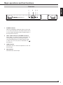
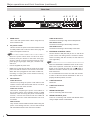
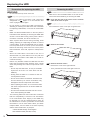
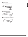
ENGLISH
HDD Extension Unit
DEUTSCH
INSTALLATION AND OPERATION MANUAL
MODEL
NEDERLANDS
ITALIANO
ESPAÑOL
FRANÇAIS
DX-ZD6UE
THIS INSTRUCTION MANUAL IS IMPORTANT TO YOU. PLEASE READ IT BEFORE USING YOUR HDD EXTENSION UNIT.
1
Caution and care
HEAVY OBJECTS SHOULD NEVER BE PLACED ON THE UNIT (E.G., MONITOR)
NEVER TOUCH OR INSERT ANY OBJECT INSIDE THE UNIT
Touching the inside of the cabinet or inserting foreign objects of any kind through the ventilation holes not only creates a safety
hazard but can also cause extensive damage.
PROTECT THE POWER CORD
Damage to the power cord may cause fire or shock hazard. If the mains cord is damaged, turn OFF the MAIN switch and carefully unplug the cord by holding the mains plug.
If this unit is moved with the power on status, the HDDs may be damaged. Ensure that more than one minute have passed since
the power cord and the connecting cords were disconnected, then move this unit.
UNPLUG THE POWER CORD DURING A LONG ABSENCE
Turn off the power and unplug the power cord during a long absence.
MAINTAIN GOOD VENTILATION
Do not obstruct the many ventilation holes on the unit. For maximum ventilation, leave some space around the unit and place
the unit on a hard level surface only, and ensure it is not covered during use. Heavy objects should never be placed on the unit.
WHEN NOT IN USE
When not in use, always turn OFF the MAIN switch.
CABINET CARE
Never use petroleum-based cleaners. They may cause deterioration or coat flaking of the unit. Clean with a soft cloth moistened
with soap and water and wipe dry.
When using chemical duster, follow the instructions.
INSTALLATION LOCATION
For excellent performance and lasting reliability install in a location that is:1. Well ventilated, out of direct sunlight and away from direct heat.
2. A solid vibration-free surface.
3. Free from high humidity, excessive dust and away from magnetic fields.
4. Please ensure that the ventilation fan located on the unit’s back panel is not blocked.
UNSUITABLE LOCATIONS
Placing the unit in the following places might shorten the product life:
• Extremely cold places, such as refrigerated warehouses and ice houses
• Places where excessive hydrogen sulfide is likely to be generated, such as hot-springs areas
• Places or locations with salt air environment.
NO OBJECTS FILLED WITH LIQUIDS, SUCH AS VASES, SHALL BE PLACED ON THE APPARATUS.
DO NOT PLACE HEAVY OBJECT ON THIS UNIT.
DO NOT STEP ONTO THIS UNIT.
WARNING:
TO PREVENT FIRE OR SHOCK HAZARD, DO NOT EXPOSE THIS APPARATUS TO RAIN OR MOISTURE.
THIS APPARATUS MUST BE GROUNDED.
This unit complies with the requirements of the EC Directive 2004/108/EC, “EMC Directive” and 2006/95/EC, “Low Voltage Directive”. The requirements for the susceptibility according to EN 55024 and the requirements for interference according to EN
55022 are observed for the operation on residential areas, business, light industrial premises and in small scale enterprises,
inside as well as outside of the building. All places of operation are characterised by their connection to the public low voltage
power supply system. This unit is manufactured in accordance with EN 60950-1.
Note: This symbol mark is for EU countries only.
This symbol mark is according to the directive 2002/96/EC Article 10 Information for users and Annex IV.
Your MITSUBISHI ELECTRIC product is designed and manufactured with high quality materials and components which can be recycled and reused.
This symbol means that electrical and electronic equipment, at their end-of-life, should be disposed of separately
from your household waste.
Please, dispose of this equipment at your local community waste collection/recycling centre.
In the European Union there are separate collection systems for used electrical and electronic product.
Please, help us to conserve the environment we live in!
WARNING:
The power cords for use in the U.S., the continent of Europe, and U.K. are included with this unit.
Use the appropriate one for your country.
The power cord for use in the U.S. is used for 120V only. Never connect to any outlet or power suply
having a different voltage or frequency.
2
The mains lead on this Unit is fitted with a non-rewireable mains plug, incorporating a 5A fuse. If you need to replace the fuse,
use a 5A fuse approved by BSI or ASTA to BS 1362, ensuring you refit the fuse cover. If the mains plug is not suitable for the
sockets in your home, and you require to remove the plug, remove the fuse, cut off the plug then dispose of the plug immediately, to avoid a possible electric shock hazard. To refit a new plug, follow these instructions; Green-and-yellow: Earth, Blue:
Neutral and Brown: Live. As the colours in the mains lead of this Unit may not correspond with the coloured markings identifying the terminals in your plug, proceed as follows.
• The wire which is coloured green-and-yellow must be connected to the terminal in the plug which is marked by the letter E
or by the safety earth symbol or coloured green or green-and-yellow.
• The wire which is coloured blue must be connected to the terminal which is marked with the letter N or coloured black.
• The wire which is coloured brown must be connected to the terminal which is marked with the letter L or coloured red.
ENGLISH
MAINS LEAD CONNECTION
Before you start recording important images, make sure to perform trial recording to ensure that images are properly recorded. Mitsubishi assumes no resonsibility or reliability for any loss of recorded data and any failure of playback data arising out
of malfunction of this unit or the connected device. It is recommended that backups of important recordings are made regularly as a precaution against possible breakdowns and accidents.
•
•
•
•
•
•
•
This unit uses a hard disk, which is a precision device. Please handle this unit with sufficient care.
Do not subject this unit to vibrations or shocks. Vibrations and shocks may cause trouble especially while the recorder is
on or the hard disc drive is being accessed.
Do not disconnect the power plug or the USB cable while the power of the unit is turned on or while recording or playing.
It is recommended to ask for inspection every one year for early detection of failure.
Do not move this unit at least one minute after the power is turned off.
If the power plug is disconnected or the breaker switch is turned off during recording, HDD may be damaged or playback
of recorded data may become impossible.
If the breaker switch is turned on and off everyday, set the timer recording to be performed only for the period that the
breaker is on and do not turn off the breaker during recording.
It is recommended to check periodically that recording is performed successfully by playing back the recorded data.
The HDD and cooling fan of this unit are driving parts. For stable recording, it is recommended that both of these parts are
replaced every 30,000 hours.
(This interval is for reference purpose only and does not indicate the warranty period of the parts.)
INSTALLATION LOCATION AND HANDLING
• Do not plug this unit into the same outlet which is being used for other large power consuming equipment such as a copying
machine and air conditioner.
• Do not place this unit close to other equipment to prevent adverse interference between them.
• Do not place this unit close to strong magnetized objects. They may cause effects on the images or loss of recorded data.
• Never apply volatile substances such as insecticides and do not put rubber- or plastic-products on the unit for a long period.
They may cause deterioration of this unit or flaking of the coating.
• Install the unit within the allowable ambient temperature range (5 °C to 40 °C) and relative humidity range (less than 80%).
Using this unit out of these ranges may adversely affect the internal parts or cause malfunction. When the temperature of the
HDD rises high, its performance may deteriorate or its lifetime may be shortened. When using this unit at a low temperature,
turn on the power and wait for 10 minutes or more before use.
WHEN MOVING THIS UNIT
• When you move this unit, make sure to turn off the power and unplug. When a strong shock is applied to this unit while it is
on, the electronic parts inside the unit may be damaged. Take care especially while the ACCESS indicator is illuminating.
• When you move this unit, wrap it with cushions to avoid shock to the internal parts.
COPYRIGHT
• This unit records images digitally. When recording copyrighted images, be careful not to infringe their copyrights.
Disclaimer
In any event, Mitsubishi assumes no responsibility or reliability for the following:
1. Disassembly, repair, or alteration of this unit by user or installer.
2. Failure or breakdown in or damage to this unit resulting from misuse or careless handling by user or installer.
3. Inconvenience or damages arising out of inability to display or record images due to any reason or cause other than breakdown or failure in this unit.
4. Failure in this unit due to combination with other equipment manufactured by a third party or inconvenience or damages
resulting from such failure.
5. Inconvenience, damages, or claims arising out of breakdown in this unit or loss of recorded video data due to replacement
of the HDD by user or installer.
6. Inconvenience or damages arising out of breakdown in this unit or inability to display or record images due to natural disaster including earthquake and storm.
7. Inconvenience, damages, or claims arising out of breakdown in this unit or loss of recorded video data due to impact or
vibration to the HDD or an environmental factor such as temperature at the installation site.
8. Demand for damages or other claim of infringement of privacy if the images monitored or recorded by user become public
or are used for any purpose other than surveillance for whatever reason.
3
Features/Contents
Features
HDD extension unit having a large-capacity hard disc drive (HDD)
This unit is equipped with a high-reliability, high-speed, and large-capacity hard disc drive.
HDD operation mode
Among 2 HDD operation modes of spanning and mirroring, you can select the desired one.
Power linkage function
The power of this unit can be turned on/off by linking with the connected MITSUBISHI digital recorder's power supply.
Warning function
This unit is equipped with the terminal for informing of abnormal temperature rise and HDD error.
Direct connection with a personal computer
You can connect this unit to a personal computer directly via a USB cable and playback the data recorded by this unit on the
personal computer using the special playback software. Consult your dealer for the special playback software.
The name of this unit is shown on the personal computer as follows.
ID number (specified by the ID rotary switch on this unit)
HDD UNIT ID** S
HDD operation mode (specified by the MODE rotary switch on this unit)
M ...... Mirroring mode
S......... Spanning mode
Contents
Important safeguards ................................................... i-iv
Caution and care ..............................................................2
Features ............................................................................4
Contents ............................................................................4
Major operations and their functions .............................5
Front view ........................................................................ 5
Rear view ......................................................................... 6
Connections ........................................................................8
Connectable recorders .................................................... 8
Connection example ........................................................ 8
Connection to link the power supply of the recorder
and this unit .................................................... 8
Precautions for connection......................................... 9
Startup ........................................................................... 10
Setting the ID number of this unit ................................... 11
Setting the ID number of this unit ...................................11
Setting the mode of this unit ...........................................12
HDD operation mode ..................................................... 12
Mode selection............................................................... 12
Replacing the HDD .........................................................14
Precautions for replacing the HDD ................................ 14
Removing the HDD ........................................................ 14
Attaching the HDD ......................................................... 16
Troubleshooting .............................................................18
Diagnosis by HDD indicators ......................................... 18
Troubleshooting ............................................................. 19
Maintenance .................................................................. 19
Specifications ...................................................................20
How to read this manual
Viewing displays
(Refer to this information when operating):
Tips
Reference information concerning operation
Notice
(Caution required):
Cautionary items concerning operation
(See reference page):
Reference item and page number
Warning
This is a class A product. In a domestic environment this product may cause radio interference in which case the user may be
required to take adequate measures.
4
Major operations and their functions
1
1
2
3 4
ENGLISH
Front view
POWER indicator
When the EXTERNAL CONTROL switch is set to OFF
or it is set to ON with the connected recorder turned
on, this indicator illuminates while the MAIN switch on
the rear panel is turned on.
2
HDD1, HDD2 indicators (ACCESS indicators)
While HDD 1 or HDD 2 is being accessed, the
corresponding indicator momentarily blinks green.
They keep blinking during recording/copying of data.
In case of an error, they blink or illuminate red. (
See page 18.)
3
TEMP indicator
Illuminates when the internal temperature of this unit
becomes high.
4
FAN indicator
Illuminates when the fan stops.
5
Major operations and their functions (continued)
Rear view
1
1
2
4 5
3
MAIN switch
HDD ALM terminal
Terminal for informing of abnormality of the HDD.
4
When the power outlet does not have an earth
terminal, ask your dealer for the earth work (pay
service). Never connect the earth terminal of the
power plug to a gas pipe, water pipe, conductor rod,
and so on.
•
Use the supplied AC power cord.
•
Make sure to plug this unit into the outlet of the same
power line that is used for the recorder connected.
When this unit is plugged into the outlet of other line,
recording or copying will not be resumed correctly
after a power failure.
3
CONT OUT terminal
Terminal for outputting the power on/off status of
the recorder. When using multiple number of HDD
extension units and using the power on/off linkage
function, connect this terminal with the CONT IN
terminal on the rear of the HDD extension unit to be
connected.
GND terminals
They are the common GND terminals. When using the
power on/off linkage function, connect this terminal
with the GND terminal on the rear of the recorder.
6
Notice
•
When the EXTERNAL CONTROL switch is set to ON,
make sure to perform “Connection to link the power
supply of the recorder and this unit” on
page 8.
When the recorder is turned on, this unit is turned on
at the same time.
•
It is recommended to link this unit with the recorder
in order to allow the internal hard disks to rest or to
properly handle a problem, if occurs.
I/O terminals
CONT IN terminal
Terminal for inputting the power on/off status of the
recorder. Connect this terminal with the DC 12V OUT
terminal on the rear of the recorder.
EXTERNAL CONTROL switch
Set this switch to ON (left side) to turn on and off the
power of this unit linking with the recorder’s switch.
When not linking with the recorder, set this switch to
OFF (right side).
Notice
•
8
FAN ALM terminal
Terminal for informing of abnormality of the fan.
AC power socket
Used to connect the power cord. Earth terminal is used
for safety. Make sure to use the 100 to 240 V plug with
earth for the power of this unit.
7
TEMP ALM terminal
Terminal for informing of high internal temperature.
This is the main power switch. When using this unit,
set this switch to ON.
2
6
5
CONT IN terminal
Reserved.
6
CONT OUT terminal
Reserved.
7
SERIAL BUS IN port
Port for connecting with the recorder.
8
SERIAL BUS OUT ports
Ports for connecting with another DX-ZD6UE when
using multiple number of DX-ZD6UE.
•
It is impossible to supply 5V DC power from this port.
•
Do not connect any devices other than DX-ZD6UE to
these output ports.
ENGLISH
Notice
7
Connections
Connectable recorders
MITSUBISHI DIGITAL RECORDER
•
DX-TL5000 series (DX-TL5000U, DX-TL5000E, DX-TL5000UA, DX-TL5000E400, DX-TL5000E(Z))
•
DX-TL4500 series (DX-TL4516E, DX-TL4516E(Z), DX-TL4516U, DX-TL4509E, DX-TL4509E(Z), DX-TL4509U)
The above stated models are connectable as of October 2007. Consult your dealer for the connection with other recorders.
Connection example
•
Connect this unit and a digital recorder by using the supplied USB cable.
•
You can connect multiple DX-ZD6UE as shown below.
Digital recorder DX-TL5000E400 (example)
IN
OUT
AUDIO IN
1
2
3
4
5
6
7
VIDEO
8
VIDEO
1
2
3
OPTION SLOT
4
Y/C
OUTPUT A OUTPUT B
CAMERA
OUT
AUDIO
CLAMPER
IN
OUT
9
10
11
12
13
14
15
OUT
16
IN
IN
CASCADE
AUDIO OUT
VIDEO CASCADE
SERIAL BUS SERIAL BUS
LAN-A
This unit
LAN-B
CLAMPER
OFF
ON
STORAGE
ALARM IN
1
2
3
4
5
6
7
8
9
10
11
12
13
14
15
16
RS-232C
ALARM OUT
10 100
CLOCK ADJ
CLOCK ADJ OUT
REC
REC STOP
EMERGENCY
RESERVED
MODE OUT 1 +
MODE OUT 1 –
MODE OUT 2 +
MODE OUT 2 –
MODE OUT 3 +
MODE OUT 3 –
MODE OUT 4 +
MODE OUT 4 –
CALL OUT +
CALL OUT –
GND
MAX 350mA
DC 12V OUT
MAIN
GND
1
2
3
4
5
6
7
8
9
10
11
12
13
14
15
16
~
COM
RS485
OUT
10
RS485
IN
PTZ
RS485 TERM +
RS485 TERM –
GND
RS422 +
RS422 –
GND
RS232
100
RESET
AC IN
100-240V
To SERIAL BUS port
To SERIAL BUS IN port
Supplied USB cable
To SERIAL BUS
OUT port
To SERIAL BUS
IN port
Supplied USB cable
Connection to link the power supply of the recorder and this unit
•
Set the EXTERNAL CONTROL switch to ON (left side) and connect the terminals as shown below. It is recommended
to link this unit with the recorder’s power supply.
•
To resume recording or copying after a power failure during normal recording or timer recording, plug this unit into the
outlet of the same power line that is used for the recorder connected.
Digital recorder DX-TL5000E400 (example)
This unit
8
Precautions for connection
•
When connecting 5 or more HDD extension units (with 2 HDDs mounted on each unit) to the digital recorder, you are
recommended to use USB cable as illustrated below to prevent recognition error of digital recorder due to different
start-up times among HDDs.
ENGLISH
Notice
Furthermore, before you start operation or when the power restores from a power failure, check that the HDDs are
recognized correctly even when a small number of HDD extension units are connected.
Digital recorder
IN
This unit
OUT
IN
This unit
OUT
IN
This unit
OUT
IN
This unit
IN
This unit
OUT
IN
This unit
OUT
IN
This unit
IN
This unit
OUT
IN
This unit
IN
This unit
OUT
OUT
IN
IN
This unit
This unit
OUT
OUT
IN
IN
This unit
This unit
* When 2 serial bus ports are used.
•
The EXTERNAL CONTROL switch is set to ON by default. In this status, this unit does not work even though you
connet the power cord and set the MAIN switch to ON.
Connect this unit and the recorder as “Connection to link the power supply of the recorder and this unit” on
10.
page
Tips
•
The available number of HDD extension units to be connected varies depending on the recorder connected. Check the
specification of the recorder.
•
You cannot connect 6 or more HDD extension units in series using serial bus.
•
The number of serial bus ports varies depending on the digital recorder connected. For stable recording, it is
recommended to use the ports of the recorder as many as possible to avoid branch connection of the extension units.
9
Connections (continued)
Startup
Step
1 Turn ON the MAIN switch on the rear of this unit.
Step
2 Turn on the MAIN switch on the rear of the recorder.
• The POWER indicator of this unit illuminates when the power supply of this unit is not linked with the recorder.
Step
3 After “POWER OFF” is displayed on the LCD of the recorder, press the POWER button on the front panel of
the recorder.
• The indicators of HDD 1 and HDD 2 on the front panel of this unit momentarily blink green.
• When the power supply of this unit is linked with the recorder, you can turn on the power of this unit by pressing the
POWER button on the front panel of the recorder.
• When the power of the recorder is turned on, the connection is completed.
Tips
•
10
For the operation of the recorder, refer to the installation and operation manual supplied with the recorder.
Setting the ID number of this unit
Step
1 Turn OFF the MAIN switch on the rear of this
unit.
Step
2 Remove the cover of this unit according to steps
1 to 3 of “Removing the HDD” on
page 14.
• The ID number is set using the ID rotary switch
inside the cover.
ENGLISH
Setting the ID number of this unit
<Inside the front cover>
ID rotary switch
Step
3 Set the ID rotary switch to the desired number.
• The ID number set in this step is displayed on the
digital recorder's menu screen that is used to register
the device.
ID number
ID
Spanning
Mirroring
rotary switch
operation
operation
0
ID00S
ID00M
1
ID01S
ID01M
2
ID02S
ID02M
3
ID03S
ID03M
4
ID04S
ID04M
5
ID05S
ID05M
6
ID06S
ID06M
7
ID07S
ID07M
8
ID08S
ID08M
9
ID09S
ID09M
A
ID10S
ID10M
B
ID11S
ID11M
C
ID12S
ID12M
D
ID13S
ID13M
E
ID14S
ID14M
F
ID15S
ID15M
Step
4 Attach the cover of this unit according to steps 9
to 11 of “Attaching the HDD” on
page 17.
Step
5 Turn ON the MAIN switch on the rear of this unit.
11
Setting the mode of this unit
Mode selection
HDD operation mode
This unit has 2 HDD operation modes as described below.
Step
1 Turn OFF the MAIN switch on the rear of this
unit.
Step
2 Remove the cover of this unit according to the
steps 1 to 3 of “Removing the HDD” on
page
14.
Spanning mode
This mode regards and uses 2 built-in HDDs as 1 HDD. The
total data capacity of 2 HDDs is available.
Notice
•
When either of the HDDs fails in the spanning mode,
both of the HDDs become unusable and the recorded
data are deleted.
• The mode is set using the MODE rotary switch inside
the cover.
<Inside the front cover>
Mirroring mode
This mode records the same data to 2 built-in HDDs
simultaneously.
Even when either of the HDDs fails, by replacing the failed
HDD, the data stored in the other HDD are automatically
copied to the newly mounted HDD and the HDDs
are restored to the condition before the failure. (Data
synchronization)
Synchronization of 500-GB data takes about 8 hours. This
time is approximate and given as a guide only, assuming
that this unit performs no other operations during the data
synchronization. Therefore, a longer time is required for
the data synchronization when the unit is in the playback or
recording mode.
MODE rotary switch
Step
• Before you change the HDD operation mode,
delete the management information according to
steps 3 to 5. You may skip these steps when you
mount an unused HDD. When you mount a used
HDD, the HDD cannot be used properly unless the
management information is deleted before changing
the HDD operation mode.
Step
4 Press the RESET button.
Step
5 After the unit boots up and the buzzer sounds,
press the TEST button.
When the data synchronization is interrupted by the
operation such as power-off, the unit resumes the
synchronization after the power is restored.
• The management information deletion function is
activated and the ACCESS indicator starts blinking.
Upon completion of the deletion, the indicator
illuminates green.
Notice
•
12
When you replace the failed HDD in the mirroring
mode, make sure to use an unused HDD. If you mount
a used HDD, delete the management information of
that HDD. (See “How to set the mode” on the right
column.) If you mount a used HDD without deleting
its management information, the data synchronization
may not be performed correctly. (Do not delete the
management information with the existing normal HDD
mounted because the data is deleted.)
3 Set the MODE rotary switch to 7.
Step
6 Set the MODE rotary switch to the number
corresponding to the desired operation mode.
MODE
rotary switch
HDD operation
mode
0
Do not use.
1
Spanning
2
Mirroring
3
Do not use.
4
Do not use.
5
Do not use.
6
Do not use.
7
Do not use.
8
Do not use.
9
Do not use.
7 Attach the cover of this unit according to steps 9
to 11 of “Attaching the HDD” on
page 17.
Step
8 Turn ON the MAIN switch on the rear of the unit.
ENGLISH
Step
13
Replacing the HDD
Precautions for replacing the HDD
Removing the HDD
WARNING
•
Do not remove the top cover of the unit.
Notice
•
Make sure to turn the MAIN switch on the rear of this
unit to OFF before attaching or removing the HDD.
Notice
•
Before you replace the HDD, read "Important
safeguards" on
pages i to iv and "Caution and
Care" on pages 2 and 3 again.
•
Do not attach or remove the HDD unnecessarily.
Attaching or removing the HDD of this unit is intended
for replacing a failed HDD, not for use as a removable
HDD.
•
Make sure that the MAIN switch on the rear panel is
turned OFF when attaching or removing the HDD. Wait
at least 1 minute after turning off the power. When a
recorder is connected, turn off the recorder, too.
•
When a power failure occurs during recording, avoid
adding, replacing or transporting the HDD. In case of
a power failure, as the recorded data may be erased,
turn the power back on to boot up the unit with the
HDD that was being used at the time of the power
failure attached. Then add, replace or transport the
HDD.
•
When the USB cable connected to this unit is
disconnected or a power failure occurs only with this
unit, data is recorded to other HDD unit in order to
continue recording.
•
HDD is very delicate. Handle the HDD with care and
follow the precautions below because even a slight
shock may damage the internal components of the
HDD.
• Do not drop the HDD. Also, do not put a metallic
object such as a coin or a screw driver into the
HDD tray.
• Gently place the HDD on a cushion so that it is
not subjected to shock.
• Do not use an electric screwdriver. Vibrations and
shocks caused by an electric screwdriver may
damage the internal components of the HDD.
• When replacing the HDD, do not knock the HDD
with other components such as another HDD and
the HDD tray.
• Do not knock the HDD with tools such as a screwdriver when replacing the HDD.
•
The following HDD has been tested and confirmed
that the compatibility is ensured. This information
is as of November 2007. Supply of this HDD may
be stopped or it may be changed without notice by
its manufacturer. Consult your dealer for the latest
information or use of other HDDs. When you attach
multiple HDDs, use the HDDs of the same capacity
and the same model name, in principle.
<Hitachi Global Storage Technologies>
HDT725050VLA360 (500 GB, S-ATA)
14
Step
1 Push the left end of the screw covers on both
sides of the cover to open.
Notice
•
Do not leave the screw cover open for general use.
Step
2 Remove the screws.
Step
3 Remove the front covers.
• Remove the cover on the right side first.
• Then, push the left cover to the right to remove.
4 Disconnect 2 cords connected to the circuit
board on the metal part.
Step
8 Pull out the HDD tray.
• Pull out the HDD tray completely.
Step
9 Remove the HDD.
• Remove 4 screws securing the HDD and then
remove the HDD from the frame.
Step
ENGLISH
Step
5 Remove the metal part.
• Remove 4 screws on the metal part.
Step
6 Pull out the HDD tray halfway.
HDD 1
Step
HDD 2
7 Remove the cords.
Notice
•
Because S-ATA connectors of HDD are very delicate,
connect or disconnect the cords gently without
applying excessive force to the connectors.
Take special care to connect or disconnect the
connectors straight in order to prevent vertical force
from being applied to them.
S-ATA connectors
15
Replacing the HDD (continued)
Attaching the HDD
Step
• Align the upper side first, then push the lower side
into the unit.
Notice
•
• Take care not to deform the springs.
When you attach multiple HDDs, attach them in the
order of HDD 1 and 2.
Step
5 Attach the metal part.
• Pass the cord to be connected to the circuit board
through the hole in the metal part.
1 Attach the new HDD onto the HDD tray with 4
screws.
• Make sure to attach the HDD in the correct orientation.
Step
6 Fix the metal part with 4 screws.
Step
7 Connect 2 cords to the circuit board on the metal
part.
Step
8 Check whether the HDD is connected properly.
Notice
•
When attaching the HDD to this unit, use the supplied
screws.
Step
2 Insert the HDD tray halfway.
Step
3 Connect the cords.
1 Set the MODE rotary switch to any number from 0 to
5.
2 While the TEST button is pressed, press the RESET
button.
3 After the unit boots up and the buzzer sounds, press
the TEST button.
Step
4 Insert the HDD tray completely.
The HDD test function is activated and tests each
HDD for 1 minute, and then the test results are
shown by the ACCESS indicator.
When the indicator illuminates green, the connection
is completed successfully.
When the indicator blinks red, the HDD is not
connected properly.
When the indicator illuminates red, the HDD is not
identified properly.
16
Step
9 Attach the front covers.
• Then, attach the right cover.
Step
10 Fix the front covers with 2 screws.
Step
11 Close the screw covers on both sides of the
cover.
ENGLISH
• Attach the left cover first and push it to the left.
Tips
•
Follow the same procedures to attach or remove HDD
2.
17
Troubleshooting
Diagnosis by HDD indicators
In the case that the HDD 1 or HDD 2 indicator on the front panel blinks or illuminates, check the problem in the HDD
according to the chart below.
START
Both indicators of HDD
1 and HDD 2 illuminate
red.
Yes
Both of the HDDs are not identified.
The S-ATA cable may not be connected
properly or a problem may occur in the
HDDs.
No
Both indicators of HDD 1
and HDD 2 blink red.
Yes
Is the operation mode
set to mirroring?
Yes
No
No
Is the MODE rotary switch set
correctly?
Either indicator of HDD 1
or HDD 2 illuminates red
and the other one blinks
red.
Yes
Is the operation mode
set to spanning or
mirroring?
The HDDs of different capacities may
be used. Check the HDD capacity.
Mirroring
Spanning
The HDD corresponding to the
illuminating indicator is not identified.
The S-ATA cable may not be connected
properly or a problem may occur in the
HDDs.
No
Either indicator of HDD 1
or HDD 2 illuminates red.
No
Is the MODE rotary switch set correctly?
Is the cable connected correctly?
18
Yes
Is the operation mode
set to mirroring?
During synchronization, a problem
occured in the source HDD and that
HDD became unidentifiable.
The synchronization cannot be
continued.
Yes
Though the HDD corresponding to the
illuminating indicator is not identified,
operation can be continued. The S-ATA
cable may not be connected properly or
a problem may occur in the HDDs.
If problems with the unit persist even after you followed the suggestions below, please stop using the unit, disconnect the
power cord and contact the retailer from whom you purchased the unit.
Description of problem
The unit does not turn on.
This unit does not work
correctly.
TEMP indicator illuminates.
FAN indicator illuminates.
Please check the following
• Is the power cord properly plugged in?
ENGLISH
Troubleshooting
• Is the EXTERNAL CONTROL switch set to ON though the DC 12 V OUT
terminal of the recorder and the CONT IN terminal of this unit are not
connected ?
• Is the USB cable connected correctly?
• Are the menus set correctly in the recorder?
• Is the number of recording devices connected within the limitation?
• Does the HDD 1 or HDD 2 indicator blink or illuminate red?
• Is the MODE rotary switch set correctly?
• Is the information of this unit displayed on the menu for registering the
device?
Is the correct data capacity displayed?
• Did you delete the management information before changing the HDD
operation mode?
• Turn off the power. Turn on the power again after the internal temperature
drops.
• Replace the fan with a new one. Ask your dealer to replace the fan.
Maintenance
The elapsed operating time, which can be a guide to know the periodic maintenance timing, is available in the menu of the
recorder. Refer to the manual of the recorder. The indication of the operating time of the recorder may vary from the actual
operating time. It is recommended to use this indication just for your reference.
When this unit is registered as a Main device, the elapsed operating time of this unit is not displayed. (The elapsed
operating time of the recorder connected with this unit is displayed.)
19
Specifications
General
Rated Power Supply:
Rated Input:
Operating Temperature:
Relative Humidity:
Altitude:
Dimensions:
Weight:
Control terminals
CONT IN
CONT OUT
100 to 240 V AC, 50/60 Hz
0.75 - 0.4 A (100-240 V)
41 °F-104 °F (5 °C to 40 °C)
Max. 80 (%)
Max. 2000 (m)
424 (Width) x 361 (Depth) x 49 (Height) (mm)
6.3 kg (with 2 HDD mounted)
Input terminal linked with the power supply of the recorder
Output terminal linked with the power supply of the recorder
(CONT OUT is the through output of CONT IN.)
For grounding
Output terminal for detecting abnormal temperature (open collector output)
Active: “Low” level voltage output, Max. current 7 mA DC.
Non active: Open, Max. voltage 24 V DC.
Output terminal for detecting fan error (open collector output)
Active: “Low” level voltage output, Max. current 7 mA DC.
Non active: Open, Max. voltage 24 V DC.
Output terminal for detecting HDD error (open collector output)
Active: “Low” level voltage output, Max. current 7 mA DC.
Non active: Open, Max. voltage 24 V DC.
GND (Ground)
TEMP ALM
FAN ALM
HDD ALM
CONT IN
CONT OUT
Reserved.
Reserved.
EXTERNAL CONTROL:
When set to ON: Power is supplied to the HDD when 12V is applied to the input terminal linked with the power supply.
When set to OFF: Power is always supplied to the HDD.
Serial bus terminal
Serial bus terminal (2 terminals)
Accessories:
(Only DX-ZD6UE is connectable.)
USB2.0 cable
Control cable
Screws
User’s manual (this manual)
Power cord
1
1
8
1
3
Control input/output terminals and circuits
TEMP ALM terminal
FAN ALM terminal
HDD ALM terminal
• Output Circuit
Output terminal
GND terminal
<Interface circuit inside the unit>
Design and specifications are subject to change without notice.
20
MITSUBISHI DIGITAL ELECTRONICS AMERICA, INC.
9351 Jeronimo Road, Irvine, CA 92618, U.S.A.
Phone 949-465-6000
www.mitsubishi-imaging.com
Tech Support 888-307-0309
[email protected]
UK
Mitsubishi Electric Europe B.V.
UK Branch Office
Visual Information Systems Division
Travellers Lane Hatfield Herts AL10 8XB
Telephone: +44 (1707)-278 684
Fax: +44 (1707)-278 541
GERMANY
Mitsubishi Electric Europe B.V.
German Branch Office
Electric Visual Systems
Gothaer Str. 8 40880 Ratingen Germany
Telephone: +49 (2102)-486 9250
Fax: +49 (2102)-486 7320
ITALY
Mitsubishi Electric Europe B.V.
Italian Branch Office
Centro Direzionale Colleoni
Palazzo Perseo - Ingresso 2, Via
Paracelso 12, 20041 Agrate Brianza, Italy
Telephone: +39 (039)-605 31
Fax: + 39 (039)-605 3214
The Netherlands
Mitsubishi Electric Benelux
A Division of Mitsubishi Electric Europe B.V.
Niiverheidsweg 23A, 3641 RP Mijdrecht
Netherlands.
Telephone: +31 (297)-282 461
Fax: +31 (297)-283 936
SPAIN
Mitsubishi Electric Europe B.V.
Spanish Branch Office
Ctra. de Rubi, 76-80 Apdo.420
08190 Sant Cugat del Valles
(Barcelona) SPAIN
Sweden
Mitsubishi Electric Scandinavia
Hammarbacken 14 Box750 SE-191 27
Sollentuna
Sweden
Telephone: +34 (93)-565 3154
Fax: +34 (93)-589 4388
Telephone: +46 (8)-625 1000
Fax: +46 (8)-35 1132
FRANCE
Mitsubishi Electric Europe B.V.
French Branch Office 25,
Boulevard des Bouvets 92741 Nanterre
Cedex
Ireland
Mitsubishi Electric Ireland
A Division of Mitsubishi Electric Europe B.V.
Westgate Business Park, Ballymount,
Dublin 24. Ireland
Telephone: +33 (1)-5568 5500
Fax: +33 (1)-5568 5731
Telephone: +353 (1)-419 8800
Fax: +353 (1)-419 8895