1
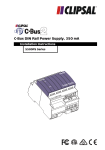
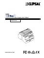
C-Bus DIN Rail Power Supply Unit, 350mA Installation Instructions 5500PS Series REGISTERED PATENT 3042248 Intelligent Building Series C-Bus 5500PS Series DIN Rail Power Supply Installation Instructions Table of Contents Section..................................................................................................... Page 1.0 Product Range ........................................................................................3 2.0 Description ..............................................................................................3 3.0 Capabilities..............................................................................................3 4.0 Wiring Instructions...................................................................................4 5.0 Connection to the C-Bus Network ...........................................................4 6.0 Status Indicators......................................................................................5 6.1 C-Bus Indicator..................................................................................5 6.2 Unit Indicator .....................................................................................5 7.0 Programming Requirements....................................................................6 8.0 Output Current Limiting ...........................................................................6 9.0 Power Surges and Short Circuit Conditions ............................................6 10.0 Megger Testing .......................................................................................6 11.0 Standards Complied................................................................................7 12.0 Important Warning...................................................................................8 13.0 Mechanical Specifications .......................................................................8 14.0 Electrical Specifications...........................................................................9 Copyright Notice Copyright 2004 Clipsal Integrated Systems Pty Ltd. All rights reserved. Trademarks • Clipsal is a registered trademark of Clipsal Australia Pty Ltd. • C-Bus and C-Bus2 are registered trademarks of Clipsal Integrated Systems Pty Ltd. • Intelligent Building Series is a registered trademark of Clipsal Integrated Systems Pty Ltd. All other logos and trademarks are the property of their respective owners. Disclaimer Clipsal Integrated Systems reserves the right to change specifications or designs described in this manual without notice and without obligation. © Copyright 2004 Clipsal Integrated Systems Pty Ltd. Page 2 Intelligent Building Series C-Bus 5500PS Series DIN Rail Power Supply Installation Instructions 1.0 Product Range 5500PS C-Bus DIN Rail Power Supply, 350mA (220-240V, 50-60 Hz) E5500TPS C-Bus DIN Rail Power Supply, 350mA (110-120V, 50-60 Hz) 2.0 Description The 5500PS Series Power Supply is the C-Bus power source, providing the power to each unit on the Network for it to operate. For ease of installation they are DIN rail mounted, measuring 4M wide (1M = 17.5 +0.5/-0.0 mm). C-Bus connection is conveniently achieved through the use of RJ45 connectors, allowing similar units to be quickly looped together. 3.0 Capabilities The 5500PS Series Power Supply provides up to 350mA of current to the isolated 36Vd.c. safety extra low voltage C-Bus Network. Each Power Supply, allowing for voltage drops due to cable resistance, can support up to 18 C-Bus devices (@ approx. 18mA per unit). A maximum of five (5) 5500PS Series Power Supply units may be connected in parallel to support the required number of devices on the C-Bus Network. The unit number limit is dictated by the maximum short circuit current of 2A. (Note: A PC interface counts as two units which should be taken into consideration when counting the number of units per Power Supply). 36V 27V Output Voltage 0 0.34A 0.38A Supply Current The minimum operating voltage of any C-Bus unit on the Network is 15Vd.c. Owing to voltage drops due to cable resistance, it is recommended that Power Supplies be distributed evenly along the C-Bus Network. Under all conditions it must be ensured that the maximum voltage drop between a C-Bus unit and the closest power supply is limited to 10V. When calculating the voltage drop the designer should consider the total C-Bus supply current flowing along the particular path of interest. For simplicity, it can be assumed that the CAT5 C-Bus cable resistance is 1 Ohm(Ω) per 10m. The DC output regulation characteristics of the unit ensures that the load will be shared fairly between multiple Power Supplies. The C-Bus Power Supply is short circuit proof, and protected against thermal or electrical overload. The unit isolates the mains power from the safety extra low voltage of the C-Bus Network. Why use a C-Bus Power Supply? C-Bus communications consist of bipolar voltage pulses superimposed on the Bus voltage. The C-Bus Power Supply Unit has been designed to have a low d.c. output resistance, while at the same time present a high a.c. impedance at the communications frequencies (between 500Hz and 20kHz). For this reason, standard off the shelf power supplies are not suitable for use with the C-Bus Network. © Copyright 2004 Clipsal Integrated Systems Pty Ltd. Page 3 Intelligent Building Series C-Bus 5500PS Series DIN Rail Power Supply Installation Instructions 4.0 Wiring Instructions C-Bus Category 5 Cable 5005C305B C-Bus2 C-Bus Network 2 8 1 7 4 6 5 3 CAT 5 Surface Box SMRJ88A5/1 C-Bus Patch Cord RJ5CB300PL NOTE: • A maximum of 5 x 5500PS C-Bus DIN Rail Power Supply units can be connected to a single C-Bus Network. • Other units which incorporate a C-Bus Power Supply (such as the 5100PS, 5104D5, 5512RVF), may be used in conjunction with the 5500PS Series DIN Power Supply, provided that the maximum 2A limit is observed (limitation imposed by CAT5 cable and RJ connector specifications). The user must also comply with any specific installation instructions given for those additional units. Please consult the C-Bus Calculator network design verification software for further details. • The installer must fix mains cables in the distribution board using cable ties or trunking as required by local wiring rules. Care must be taken not to allow copper strands to enter the DIN unit’s apertures. • A maximum torque of 1.4Nm should be applied to the mains rated screw terminals. • Rubber bungs are supplied (3 off) for unused RJ45 connectors, to stop foreign bodies from entering the unit. Always ensure these bungs are installed when the Unit is to be mounted inside a mains rated enclosure. • Use copper wire only. 5.0 Connection to the C-Bus Network Installation requires connection to the unshielded twisted pair C-Bus Network Cable. This illustration shows the recommended technique for cable termination giving the best electrical performance. It is required that Category 5 data cable is used, Clipsal catalogue number 5005C305B. © Copyright 2004 Clipsal Integrated Systems Pty Ltd. Page 4 Intelligent Building Series RJ Pin 1 2 3 4 5 6 7 8 C-Bus 5500PS Series DIN Rail Power Supply Installation Instructions C-Bus Connection Colour Remote ON * Remote ON * C-Bus Neg (-) C-Bus Pos (+) C-Bus Neg (-) C-Bus Pos (+) Remote OFF * Remote OFF * Green/White Green Orange/White Blue Blue/White Orange Brown/White Brown * (Not used by 5500PS unit) 6.0 Status Indicators 6.1 C-Bus Indicator This indicator shows the status of the C-Bus Network at this unit. If sufficient network voltage and a valid C-Bus Clock signal are present then the ‘OK’ signal will be displayed (continuous green light). If a Network is connected which has more current load than the power supplies can support, then this indicator will flash to show a marginal Network voltage. If there is no C-Bus Clock present then this indicator will not light. Indicator Status Meaning On Flashing Off Power on and functional Insufficient power to support Network No C-Bus connected No C-Bus Clock Signal present Further debugging of possible Network problems can be achieved with the Clipsal C-Bus Network Analyser tool (5100NA). 6.2 Unit Indicator This indicator shows the status of the individual unit. When C-Bus is supplied to the unit, ‘OK’ will be displayed (continuous green light). If any of the four channels have been toggled (using Override facilities) into a state other than is present on the C-Bus network, this indicator will flash with a 90% ON duty cycle. This applies to either Local or Remote Override inputs. Indicator Status Meaning On Flashing Off Normal operation Unit in override mode No C-Bus connected © Copyright 2004 Clipsal Integrated Systems Pty Ltd. Page 5 Intelligent Building Series C-Bus 5500PS Series DIN Rail Power Supply Installation Instructions 7.0 Programming Requirements Unlike other C-Bus units, the Power Supply does not require any programming. 8.0 Output Current Limiting One of the many advantages of the C-Bus extra low d.c. operating voltage, is that connections can be made whilst the Network is still powered up. Should a short circuit occur while this is happening, the Power Supply’s output current limiting / overload circuitry will protect it from damage for an indefinite period of time. 9.0 Power Surges and Short Circuit Conditions The mains voltage must be limited to the range specified for any unit, which is mains powered. Each Unit incorporates transient protection circuitry. Additional external power surge protection devices should be used to enhance system immunity to power surges. It is strongly recommended that overvoltage equipment such as the Clipsal 970 be installed at the switchboard. 10.0 Megger Testing Megger testing must never be performed on the C-Bus data cabling or terminals as it may degrade the performance of the Network. Megger testing of mains wiring of an electrical installation that has C-Bus Units connected will not cause any damage to C-Bus Units. Since C-Bus Units contain electronic components, the installer should interpret megger readings with due regard to the nature of the circuit connection. © Copyright 2004 Clipsal Integrated Systems Pty Ltd. Page 6 Intelligent Building Series 11.0 C-Bus 5500PS Series DIN Rail Power Supply Installation Instructions Standards Complied DECLARATIONS OF CONFORMITY European Directives and Standards Model 5500PS complies with the following: European Council Directive 89/336/EEC EMC Directive Standard IEC61204-3; EN61204-3 EN61000-3-2 EN61000-3-3 IEC61000-4-2 IEC61000-4-3 IEC61000-4-4 IEC61000-4-5 IEC61000-4-6 BS/EN 61000-4-11 97/32C/EEC IEC 61558-1 IEC 61558-2-17 Low Voltage Directive Title LV Power Supplies EMC Standard EMC LF Standard EMC LF Standard Immunity to ESD Immunity to RFI Immunity to EFT Immunity to Surge Voltages Immunity to Conducted RFI Immunity to Voltage Dips and Interruptions Transformer Safety Standard Transformer Safety Standard Australian/New Zealand EMC & Electrical Safety Frameworks and Standards Model 5500PS complies with the following: Regulations EMC (C-Tick) Electrical Safety Standard IEC61204-3; EN61204-3 EN61000-3-2 EN61000-3-3 AS/NZS 3100 AS/NZS 3108; IEC 742 Title LV Power Supplies EMC Standard EMC LF Standard EMC LF Standard General Requirements for Electrical Equipment Requirements for Safety Extra Low Voltage U.S. and Canadian Product Safety Standards and U.S. FCC Regulations Model E5500TPS complies with the following: Standards/Regulations CSA C22.2 No. 107.1 UL1012 Title General Use Power Supplies Power Units Other Than Class 2 Tested to FCC Standards for Home or Office Use FCC Part 15 ANSI C63.4 3042248 Supplemental Information This device complies with part 15 of the FCC Rules. Operation is subject to the following two conditions: (1) this device may not cause harmful interference, and (2) this device must accept any interference received, including interference that may cause undesirable operation Class B Product NOTE: This equipment has been tested and found to comply with the limits for a Class B digital device, pursuant to Part 15 of the FCC Rules. These limits are designed to provide reasonable protection against harmful interference in a residential installation. This equipment generates, uses and can radiate radio frequency energy and, if not installed and used in accordance with the instructions, may cause harmful interference to radio communications. However, there is no guarantee that interference will not occur in a particular installation. If this equipment does cause harmful interference to radio or television reception, which can be determined by turning the equipment off and on, the user is encouraged to try to correct the interference by one or more of the following measures: • • • • Reorient or relocate the receiving antenna Increase the separation between the equipment and receiver Connect the equipment into an outlet on a circuit different from that to which the receiver is connected Consult the dealer or an experienced radio/TV technician for help Warning: Any changes or modifications not expressively approved by Clipsal Integrated Systems could void the user's authority to operate this equipment. © Copyright 2004 Clipsal Integrated Systems Pty Ltd. Page 7 Intelligent Building Series C-Bus 5500PS Series DIN Rail Power Supply Installation Instructions 12.0 Important Warning The use of any non-approved software in conjunction with the hardware installation without the written consent of Clipsal Integrated Systems may void any warranties applicable to the hardware. 13.0 Mechanical Specifications 65 mm (2.6") 72 mm (2.84") 85 mm (3.35") No user serviceable parts inside. © Copyright 2004 Clipsal Integrated Systems Pty Ltd. Page 8 Intelligent Building Series 14.0 C-Bus 5500PS Series DIN Rail Power Supply Installation Instructions Electrical Specifications Catalogue No. Nominal Supply Voltage Frequency Range(s) C-Bus Supply Voltage C-Bus Current Output DC Output Resistance AC Input Impedance Electrical Isolation Status Indicators Maximum Number of Units on a Single C-Bus Network Load Rating Power Supply Type Quiescent Power Warm Up Time Dimensions Mains Terminals Weight C-Bus Connections Operating Temperature Range Operating Humidity Range 5500PS 220-240V~ E5500TPS 110-120V~ 47-53Hz and 57-63Hz 15-36V DC @ 350mA Sources 350mA to the C-Bus Network with mains power connected Approx. 22Ω >60kΩ @1kHz 3.75kV RMS from C-Bus to Mains C-Bus Indicator On Flashing Off Unit Indicator On Off C-Bus Network Status Voltage 20V DC Voltage < 20V DC Voltage < 15V DC Mains Power Status Present Fail 5 350mA Able to support up to 18 units (@ 18mA each) on the C-Bus Network. High Impedance Switch Mode Power Supply 15 Watts Max 3 seconds 72 x 85 x 65 mm (2.84 x 3.35 x 2.6 inches) 2 2 Accommodates 2 x 1.5mm or 1 x 2.5mm (2 x 16 AWG or 1 x 13 AWG) 200g (7oz) 2 x RJ45 sockets 0 0 0 - 45 C (32 - 113 F) 10 – 95% RH © Copyright 2004 Clipsal Integrated Systems Pty Ltd. Page 9 Intelligent Building Series C-Bus 5500PS Series DIN Rail Power Supply Installation Instructions NOTES: © Copyright 2004 Clipsal Integrated Systems Pty Ltd. Page 10 Intelligent Building Series © Copyright 2004 C-Bus 5500PS Series DIN Rail Power Supply Installation Instructions Clipsal Integrated Systems Pty Ltd. Page 11 Further Information For further information about configuring this product and other C-Bus devices, please consult the documentation supplied. Further assistance can be obtained as follows: • C-Bus Manuals The 5000M/2 C-Bus Technical Manual provides a comprehensive and definitive guide to Clipsal C-Bus. Includes hardware and software specifications, product datasheets, system design and installation guides, and software overview with fully worked programming examples. • C-Bus Installation Software The 5000S/2 C-Bus Installation Software (includes 5000M/2 C-Bus Technical Manual) may be used to unlock the power and flexibility of Clipsal C-Bus. Unit operation may be completely customised to suit user requirements. Advanced control functions may be programmed. • C-Bus Installer Training Courses Contact your nearest Clipsal Integrated Systems Sales or Technical Support Officer and enquire about Clipsal C-Bus Installer Training and Certification Programs today !! • Technical Support and Troubleshooting For further assistance, please consult your nearest Clipsal Integrated Systems Sales Representative or Technical Support Officer. Technical Support Hotline Technical Support Email Sales Support Email Clipsal Integrated Systems Website 1 300 722 247 (Cost 25¢ per call, Australia Only) [email protected] [email protected] clipsal.com/cis Products of Clipsal Integrated Systems Pty Ltd ABN 15 089 444 931 Head Office 12 Park Terrace, Bowden South Australia 5007 International Phone +61 8 8440 0500 International Fax +61 8 8346 0845 Internet clipsal.com/cis E-Mail [email protected] 10358562