1
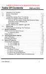
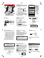
6151-SS-CE2Y-LX Manual
7/20/00
12:15 PM
Page 1
Code Encryptor II
Wiring Diagram
Location of the control module is the most important determining factor for range and
reliability of your Code Encryptor. Select a location that is as centrally located as possible. Keep in mind that your customer will want to control the operation of the garage
door from the driveway, and will also expect the use of the remote for alarm On/Off
in the area of entry and exit.
Patent Pending - Part #CE2Y-LX
Recommended
placement for
Code Encryptor
Attic
Bedroom
Point of Entry
Button 2
*Moose panels connect to
Button 1
white of keypad
Green
Connect to green of keypad
Gray
(-) Channel 2 Timed Output
Red/White
Channel 2 N/O relay
White
CODE
ENCRYPTOR
Button 4
Button 3
Channel 2 Common
(Garage Door Pushbutton)
Brown
ith
Now w
larm
atic A n
m
o
t
u
o
A
niti
Recog
Connect to yellow of keypad
(Garage Door Pushbutton)
Garage
Basement
Yellow
Channel 3 Common
(5amp)
Button 1
Button 2
Button 3
Alarm ON/STAY
Alarm OFF
Garage Door
OPEN/CLOSE
PANIC OUTPUT Hold Buttons 1 and 2
for 3 seconds
Button 4
RELAY OUTPUT
Since the Code Encryptor uses the communication bus wires from the keypad, you may
want to place the receiver in or near the garage to easily control the following
• Easy connection to the garage door push button
• Easy visual LED status mounting location
• Easy connection to the keypad wires for complete alarm control
Although you can wire at the panel, it may reduce labor by installing the Code
Encryptor II receiver at the point of entry. In most cases that is the garage which will
provide an easy installation for garage door Open/Close, status indicator and alarm
controls through the keypad. DO NOT MOUNT THE CONTROL MODULE IN
THE ALARM PANELS METAL ENCLOSURE.
1
Blue/Green Channel 3 N/C (5amp)
Installation
Wiring and Auto Recognition
Automatic Recognition Continued:
Red
Black
Yellow
Green
COMPLETE STEPS 1-8
Step 1) Unplug the receiver from the wire harness.
Step 2) Wire the Red, Black, Yellow and Green to the keypad.
Number of Flashes
1
Installation Manual
Street Smart Security
Aux +
Aux Keypad Data Line
Keypad Data Line
Black
RED
BLACK
GREEN
YELLOW
Red
Alarm Panel
CODE
ENCRYPTOR
+ Aux
Green
Yellow
Channel 3
Jumpers
1 2 3
4 5 6
7 8 9
Program
Button
Step 3) Make sure the alarm panel is powered up and operating.
Step 4) While watching the LED light on the Control module, plug the receiver into
the Code Encryptor II harness.
Step 5) The LED will blink 1 time on power up, after 2 seconds COUNT the flashes
that you see. The corresponding flashes will indicate which panel the Code
Encryptor II has detected.
Alarm
Keypad
(5amp)
Red
+12VDC
Black
(-) Ground
Purple
LED (-) Output
2
3
4
5
6
7
8
9
10
11
12
Connect to Keypad Red or Aux (+)
Connect to Keypad Black or Aux (-)
Connect to Keypad Green
Connect to Keypad Yellow
*Moose ZX200/400/900/950 Connect to the White wire.
NOTE: You can make these connections at the panel or at the keypad
itself. If you place the Code Encryptor II in the garage or any other
location away from the panel you may choose to wire the Code
Encryptor II directly to the keypad.
LED
Brown/White Channel 3 N/O
2
Alarm Panel detected by the CE II
No Alarm connected (CE II defaults to relay mode)
SEE PAGE 15 “Default Mode”
Napco 1000E Series (including 1008E, 1016E, etc.)
Moose Z880/Z900/Z950
Caddx 8600E, 8980E
Ademco Non Addressable
Ademco Addressable
DSC 1555/1565/5010 (Power 832)/5015/580
DSC 1550, 2525, 2550, 3000
Moose ZX200/ZX300/ZX400
Moose Z1100E, ADT A910
Moose Z1100
Go to Mandatory Programming (Steps 6, 7 and 8)
NOTE: If the CEII does not detect correctly,
call Technical Toll Free 888-768-2846
7am-5pm PST
4
3
5
Mandatory Programming
Mandatory Programming Continued
LED Wiring
Programming a User Code is mandatory when using the Code Encryptor II. This
gives the Code Encryptor microprocessor a User Code to arm and disarm the panel.
Press and Release button #1
Press and Release button #2
Press and Hold buttons 1 for 3 seconds
Press and Hold buttons 1 and 2 for 3 seconds
DO NOT CONNECT LED DIRECTLY TO GROUND!
Step 6) Verify that the four-digit code you plan to teach the Code Encryptor II is a
valid four-digit user code. Example: From the keypad use that four-digit
code to arm the panel. If the panel arms, that is a good code. If it does
not, program that user code into the alarm panel. – The Code Encryptor II
uses that four-digit code to arm and disarm the panel, thus that code must
be valid.*
Step 7) Press and HOLD the program button on the receiver. The light will come
ON and stay ON for three seconds then turn OFF. Once the light turns
off, RELEASE the program button, the light will begin to flash rapidly.
Step 8) Using the keypad, slowly and firmly enter the four-digit user code. After
the fourth entry the LED will stop flashing. This code has now been
entered into the Code Encryptor’s non-volatile memory. The Code
Encryptor will remember this user code in the event of a power failure. To
change to a new user code, repeat steps 7 and 8 above.
*NOTE: We recommend using a user code that the customer cannot
change. If the user code that is programmed into the CE Module is
changed, the Code Encryptor II will not disarm the alarm panel.
Alarm “Away”
Alarm “Disarm”
Alarm “Stay” or “Bypass”
“Panic”
Red (Aux+)
NOTE: The Code Encryptor II will arm in the AWAY mode even if you
are outside the house. You do not have to arm the alarm before you
exit. We do however recommend that you Arm the alarm system within sight of the status LED or keypad to verify that the alarm has
received and responded to your remote request.
The Code Encryptor II on the following panels self enroll themselves as a specific
keypad address code.
• Ademco addressable
Address #3
• Moose ZX200/ZX400 addressable
Address #4
DO NOT USE ANY OF THESE ADDRESS CODES IF YOU ARE USING ONE OF THE
ABOVE PANELS. EXAMPLE: If you are using an Ademco Addressable, no keypads
can use address #3 since the CE II will automatically enroll itself as address #3.
6
The LED is a low voltage type and must run through the Code Encryptor II. If you
attempt to connect the purple wire directly to ground (-) the LED will burn and will
NOT operate again.
Go TO Channel 2 Outputs
7
Channel 2 Outputs
Channel 2 Timed Output
(Every time button #3 is pressed, two outputs happen simultaneously.)
Every time you press button 3 on the Code Encryptor II remote the Gray wire sends
a 500ma (-) output for 3 minutes.
Output #1
Momentary Contact Closure for Opening and Closing
garage door (See Garage Door Interface)
Output #2
500ma (-) output for 3 minutes, (See Channel 2 Timed Output)
Garage Door Interface
All garage doors have a wall mounted push button that activates the door via a
two-wire connection. Make your connection at the push button switch or at the
garage door motor where these two wires terminate. The Code Encryptor II will
interface with this connection by attaching the red/white and white wires from the
Code Encryptor II to these two wires. If you choose to connect to the motor, trace the
wires from the push button to the motor to determine the proper connection point.
Most garage doors (except MOM Crusader models) use terminals #1 and #2. For
MOM Crusader models, use terminals #2 and #3.
Garage Door Motor
Terminals
1 2 3
Red/White
(Channel 2 output)
Application #1 - If you hardwire the garage door you can use this output to
trigger a 12VDC relay that will energize when you open or close your garage door
extending your entry/exit delay by another 3 minutes. For security, you can make
the entry delay minimal so if a thief enters through the garage, the entry delay will
be short. If the homeowner opens the garage with our Code Encryptor II we will
extend the entry delay by 3 minutes. If you are using the status output in the
garage then you may not need this extra time, as our remote can immediately
de-activate the alarm system and you will receive visual indication the alarm is
disarmed. NOTE: If you are using this output see additional
programmability on page 20.
Application #2 - You can use this output to drive entry/exit illumination. Every
time the customer enters or exits the house this output can trigger a relay or an
X-10 powerflash module to interface with driveway, porch or Malibu lighting,
illuminating their way as they leave and return home. The output activates
automatically when you press button 3 on the Code Encryptor II remote and will
shut off after 3 minutes. NOTE: If you are using this output see additional
programmability on page 20.
Gray Wire (-)
White
(Channel 2 common)
9
PurpleConnect to purple
of the wire harness.
SEE PAGE 16 FOR DSC 1550 AND CADDX 8980E.
Aux (+)
12VDC
8
Channel 3 Applications
Press and Release button #4
See Relay Output
Relay Output
(Not applicable for DSC 1550 or Caddx 8980E, see page 16.)
Occasionally, you may want to use Channel 3 for control of optional accessories (i.e.,
Malibu lighting, sprinklers, X-10 automation). The Code Encryptor II provides the
ability to reconfigure Channel 3 to a variety of popular outputs using the on-board
jumpers. The output provided from the Code Encryptor II is a 5amp from C relay
(Common, N/O, N/C).
Jumper Configuration
Channel 3 Output Type
Both jumpers in (default)
Momentary output
Jumper closest to the harness removed
Latching (on/off) output
Jumper farthest from the harness removed
75sec timed output
Both jumpers out
150sec timed output
This output is a 5amp Form C relay (Common, N/O/, N/C). To energize relay, press
and release button number 4. You must RELEASE the button before the relay will
energize.
X-10
Powerflash Module
10
11
6151-SS-CE2Y-LX Manual
7/20/00
12:15 PM
Page 2
Panic Mode
Panic Continued
Press and hold buttons 1 and 2 on the remote control for at least 3 seconds. This will
cause the panel to go into a panic mode. Press button 2 to disarm the panel. FOR
DSC 1555/832 AND MOOSE ZX200/ZX400 YOU MUST ENTER YOUR
FOUR-DIGIT USER CODE TO CANCEL THE REMOTE PANIC. THE REMOTE
WILL NOT CANCEL A PANIC.
DEACTIVATING THE PANIC FEATURE:
In the event the user does not want to access a panic button through the remote
control, it can be de-activated from the Code Encryptor II’s memory.
Step 1) Unplug the wire harness from the Code Encryptor II.
Step 2) Press and HOLD the program button.
Step 3) While HOLDING the program button, plug the Code Encryptor II harness
back in. The LED light located on the front will turn ON.
Step 4) Wait until the light turns “OFF”.
Step 5) Once the light has turned “OFF” release the button
To Add or Delete Remotes
ACTIVATING THE PANIC MODE
NOTE: This is the default setting of the Code Encryptor II.
If you have previously programmed remote panic “OFF” and would like to turn it
back “ON” follow the steps below. If this is a NEW installation Panic “ON” is the
DEFAULT setting for the Code Encryptor II.
Step 1) Unplug the wire harness from the Code Encryptor II.
Step 2) Press and HOLD the program button.
Step 3) While HOLDING the program button, plug the Code Encryptor II harness
back in. The LED light located on the front will turn ON.
Step 4) Immediately release the program button.
IF NECESSARY, PROGRAM THE ALARM PANEL FOR KEYPAD PANIC.
Installation for Keyswitch Arming
Red
Black
Brown/White
Brown
Aux +
Aux Zone programmed for keyswitch arming
Common adjacent to zone
Black
13
14
• DSC 1550 or Caddx 8980E panels work differently than other panels. When
either of the two alarm systems are armed they automatically arm in the STAY or
BYPASS mode until an entry/exit zone is tripped.
• Because of this panel set up, the Code Encryptor II has provisions to overcome this
problem.
TO DELETE ALL REMOTES
METHOD #1
To delete a lost or stolen remote from the Code Encryptor II, you must purge the
entire memory. This will delete all of the current remotes. You will then have to add
them back in one at a time. To purge the memory, disarm the panel. Enter 76278
from the keypad. The keypad on most panels will “beep” or the lights will turn off
momentarily to confirm delete. Follow the instructions on page 14 (To Add a New
Remote).
DSC 1550 and Caddx 8980E
If you are using one of these two panels follow the instructions below.
Step 1) Verify that the Code Encryptor II recognizes the alarm system as a Caddx
8980E or a DSC 1550 (see page 5)
Step 2) Use the Channel 3 relay wires to bypass the zone.
Step 3) Remove both jumpers located next to the wire harness
Every time the Code Encryptor II is armed in the Away mode, the relay will energize
for 1 full second to open or close the Entry/Exit zone. If the customer is already
outside the house when the panel is armed, the relay will trigger that zone
automatically to move the panel from BYPASS to Away mode.
Red
Black
Alarm Panel
METHOD #2
To delete a lost or stolen remote from the Code Encryptor II, you must purge the
entire memory. This will delete all of the current remotes. You will then have to add
them back into memory. To purge, PRESS AND HOLD the program button, the
light will come ON for four seconds, then go OFF, and finally it will come ON again,
indicating that all the remotes in memory have been purged. Release the program
button and follow the instructions on page 14 (To Add a New Remote).
Red
Alarm Panel
CODE
ENCRYPTOR
Zone programmed
for keyswitch arming
METHOD #2
To add a remote to your Code Encryptor II PRESS AND RELEASE the program
button on the receiver. The light on the receiver will come ON. Immediately PRESS
button 1 on the new remote control THREE TIMES. The light on the receiver should
go OFF, indicating the remote has been learned. If the light on the receiver stays
ON, the remote has not been learned. Remove and replace the harness, wait 15
seconds while auto recognition occurs and follow these instructions again.
The Code Encryptor II can hold up to seven remotes.
12
DEFAULT MODE:
• If the Code Encryptor II fails to recognize any of the data coming from the keypad
wires, it will automatically default to a relay mode for button #1
• If this happens, verify that you are properly wired to one of the alarms listed on
page 5.
• If you have connected the CE II to an alarm it does not recognize, follow the
wiring below for a keyswitch mode.
• Program a selected zone as “Keyswitch Arming.”
• Do not use the green or yellow wires.
TO ADD A NEW REMOTE
METHOD #1
To add a remote to your Code Encryptor II, disarm the panel and Enter 78738
from the keypad. The system will arm in the “STAY” mode. Press button #1 until the
arm system disarms. It should take a total of four presses. THIS FEATURE IS NOT
AVAILABLE ON THE MOOSE ZX200/ZX400.
Brown
CODE
ENCRYPTOR
Zone programmed
as an entry/exit
Brown/White
Resistor should be in-line OR across
the zone, whichever clears the zone.
15
Brown
Brown/White
Channel 3 wires offer N/O and N/C contacts.
Utilize the wires to open or close the zone based on your installation.
Troubleshooting
Specifications
PROBLEM: I press Button #1 but nothing happens.
SOLUTION: 1) Did you teach the Code Encryptor II a VALID four-digit user code?
Note: The code you teach the Code Encryptor II must be a master
code or one of the current user codes.
2) Press button #3, if you do NOT hear a “click” at
the receiver, GO TO PAGE 14 and learn that remote into the Code
Encryptor II.
RECEIVER
• 12VDC Power Input
• Channels 1 Data outputs
• Channel 2 Relay N/O, Comm (10amp)
• Channel 3 selectable: Form C Relay (N/O, N/C, Comm) 5amp
This output can be reconfigured from a pulsed output to a latching, 75 second
timed or 150 second timed output.
• Channel 3 - Keypad panic data output (Programmable On or OFF)
Frequency 303Mhz
Stand by Power Consumption 15ma
Temperature Range -5°F to 160°F (Indoor use only)
PROBLEM: I press and hold button s#1 and 2 and I do not get a panic.
SOLUTION: 1) Did you program the panel for keypad panic?
2) To program the Code Encryptor II for panic GO TO PAGE 13.
PROBLEM: I am using a DSC 1555 or a Power 832 and the alarm will not
ARM with the remote.
SOLUTION: Make sure you program the Alarm panel for “Quick Key Enable”
Section 015 #4 light “ON”. Power down the alarm panel and power
it back up. Wait at least 60 seconds before you attempt to use the
remote control.
PROBLEM: I am using a DSC 1555 or a Power 832 and the alarm will not
DISARM with the remote.
SOLUTION: Enter panel programming. Go to section 017. Make sure light #1 is on.
PROBLEM: I am using a Moose Z900/Z950/Z1100/Z1100E/ADT A910
and it is mis-identifying.
SOLUTION: Close zone one while plugging the CE II in.
PROBLEM: Unit does not seem to identify the panel I am using.
SOLUTION: Call technical 888-768-2846.
18
Street Smart Limited Warranty
Street Smart, a Division of Pittway Corporation, and it’s divisions, subsidiaries and affiliates
(“Seller”), 12925 Brook Printer Place, Suite 410 Poway, California 92064, warrants its products
to be in conformance with its own plans and specifications and to be free from defects in materials and workmanship under normal use and service for 24 months from the date stamp control
on the product or, for products not having a Street Smart date stamp, for 12 months from date
of original purchase unless the installation instructions or catalog sets forth a shorter period, in
which case the shorter period shall apply. Seller's obligation shall be limited to repairing or
replacing, at it s option, free of charge for materials or labor, any product which is proved not in
compliance with Seller's specifications or proves defective in materials or workmanship under
normal use and service. Seller shall have not obligation under this Limited Warranty or otherwise if the product is altered or improperly repaired or serviced by anyone other than Street
Smart factory service. For warranty service, return product transportation prepaid, to Street
Smart Factory Service, 12925 Brook Printer Place, Ste. 410, Poway, California 92064.
THERE ARE NO WARRANTIES, EXPRESS OR IMPLIED, OF MERCHANTABILITY, OR FITNESS FOR A PARTICULAR PURPOSE OR OTHERWISE, WHICH EXTEND BEYOND THE DESCRIPTION ON THE FACE HEREOF.
IN NO CASE SHALL SELLER BE LIABLE TO ANYONE FOR ANY CONSEQUENTIAL OR INCIDENTAL DAMAGES FOR BREACH OF THIS OR ANY OTHER WARRANTY, EXPRESS OR IMPLIED, OR UPON ANY OTHER
BASIS OR LIABILITY WHATSOEVER, EVEN IF THE LOSS OR DAMAGE IS CAUSED BY THE SELLER'S OWN
NEGLIGENCE OR FAULT.
Seller does not represent that the products it sells may not be compromised or circumvented; that
the products will prevent any personal injury or property loss by burglary, robbery, fire or otherwise;
or that the products will in all cases provide adequate warning or protection. Customer understands
that a properly installed and maintained alarm may only reduce the risk of a burglary, robbery, fire or
other events occurring without providing an alarm, but it is not insurance or a guarantee that such will
not occur or that there will be no personal injury or property loss as a result. CONSEQUENTLY, SELLER
SHALL HAVE NO LIABILITY FOR ANY PERSONAL INJURY, PROPERTY DAMAGE OR OTHER LOSS BASED
ON A CLAIM THE PRODUCT FAILED TO GIVE WARNING. HOWEVER, IF SELLER IS HELD LIABLE, WHERE
DIRECTLY OR INDIRECTLY, FOR ANY LOSS OR DAMAGE ARISING UNDER THIS LIMITED WARRANTY OR
OTHERWISE, REGARDLESS OF CAUSE OR ORIGIN, SELLER'S MAXIMUM LIABILITY SHALL NOT IN ANY
CASE EXCEED THE PURCHASE PRICE OF THE PRODUCT, WHICH SHALL BE THE COMPLETE AND EXCLUSIVE REMEDY AGAINST SELLER. This warranty replaces any previous warranties and is the only warranty made by Seller or this product. No increase or alteration, written or verbal, of the obligations
of this Limited Warranty is authorized.
21
16
17
19
20
REMOTE CONTROL
Battery 12VDC Mini (Part #GP23A) Replace battery once a year.
Range 150+ feet
CHANNEL 3 OUTPUT
Both jumpers in (default)
Jumper closest to the harness removed
Jumper farthest from the harness removed
Both jumpers out
Momentary output
Latching (on/off) output
75sec timed output
150sec timed output
STREET SMART SECURITY TECHNICAL CAN BE REACHED
12925 Brookprinter Place, Suite 410, Poway, CA 92064
M-F 7AM-5PM PST AT (888) 768-2846 OR (619) 513-9352-FAX
Federal Communications Commission
(FCC) Statement
Canadian Department of
Communications (DOC) Statement
This equipment has been tested to FCC requirements and has been found acceptable for use.
The FCC requires the following statement for your information:
This equipment generates and uses radio frequency energy and if not installed and used
properly, that is, in strict accordance with the manufacturer's instructions, may cause interference to radio and television reception. It has been type tested and found to comply with the
limits for a Class B computing device in accordance with the specifications in Part 15 of FCC
Rules, which are designed to provide reasonable protection against such interference in a residential installation. However, there is no guarantee that interference will not occur in a particular installation. If this equipment does cause interferences to radio or television reception ,
which can be determined by turning the equipment off and on, the user is encouraged to try to
correct the interference by one or more of the following measures:
• If using an indoor antenna, have a quality outdoor antenna installed.
• Reorient the receiving antenna until interference is reduced or eliminated
• Move the receiver away from the control/communicator.
• Move the antenna leads away from any wire runs to the control/communicator.
• Plug the control/communicator into a different outlet so that it and the receiver are on
different branch circuits.
If necessary, the user should consult the dealer or an experienced radio/television
technician for additional suggestions.
The user or installer may find the following booklets prepared by the Federal
Communications Commission helpful: “Interference Handbook”
This booklet is available from the U.S. Government Printing Office, Washington, DC 20402.
The user shall not make any changes or modifications to the equipment unless authorized by
the installation instructions or User’s Manual. Unauthorized changes or modifications could
void the user’s authority to operate the equipment.
NOTICE: The Canadian Department of Communications label identifies certified
equipment. This certification means that the equipment meets certain
telecommunications network protective, operational and safety requirements. The
Department does not guarantee the equipment will operate to the user's satisfaction .
Before installing this equipment, users should ensure that it is permissible to be
connected to the facilities of the local telecommunications company. The equipment
must also be installed using an acceptable method of connection. In some cases, the
company's inside wiring associated with a single line individual service may be
extended by means of certified connector assembly (telephone extension cord). The
customer should be aware that compliance with the above conditions may not prevent
degradation of service in some situations.
Repairs to certified equipment should be made by an authorized Canadian
maintenance facility designed by the supplier. Any repairs or alterations made by the
user to this equipment, or equipment malfunctions, may give the telecommunications
company cause to request the user to disconnect the equipment.
Users should ensure for their own protection that the electrical ground connections
of the power utility, telephone lines and internal metallic water pipe system, if present, are connected together. This precaution may be particularly important to rural
areas.
CAUTION: User should not attempt to make such connections themselves, but should
contact the appropriate electric inspection authority, or electrician, as appropriate.
The Load Number (LN) assigned to each terminal device denotes he percentage of
the total load to be connected to a telephone loop which is used by the device, to
prevent overloading. The termination on a loop may consist of any combination of
devices subject only to the requirement that the total of the Load Numbers of all the
devices does not exceed 100.
23
22