1
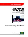
Interactive Fire Alarm System
Release 3
Commissioning Handbook
Protecting life, environment and property...
P-ASAFE/EE Rev. E, 2005-02-16
COPYRIGHT ©
This publication, or parts thereof, may not
be reproduced in any form, by any
method, for any purpose.
Autronica Fire and Security AS and its
subsidaries assume no reponsibility for
any errors that may appear in the
publication, or for damages arising from
the information in it. No information in this
publication should be regarded as a
warranty made by Autronica Fire and
Security. The information in this
publication may be updated without
notice.
Product names mentioned in this
publication may be trademarks. They are
used only for identification.
Table of Contents
Table of Contents
1. Introduction.......................................................................4
1.1
1.2
1.3
About the Handbook ......................................................................... 4
The Reader ....................................................................................... 4
Reference Documentation ................................................................ 4
2. Verifying the Loops ..........................................................5
2.1
2.2
AS-2000 Loop Diagnostic Tool ......................................................... 5
Verification Procedure....................................................................... 5
3. Consistency Check of Configuration Data .....................6
3.1
3.2
3.3
3.4
3.5
Introduction........................................................................................ 6
Parameters Used for the Consistency Check ................................... 6
Importing Loop Data from the AS-2000 Tool .................................... 7
Consistency Check Using the AS-2000 / Config Mismatch Tool ...... 7
Generating Configuration Files ......................................................... 7
4. Commissioning Procedure ..............................................8
4.1
4.2
4.3
Verifying the System Before Startup ................................................. 9
4.1.1 Recommended Equipment ..................................................... 9
4.1.2 Before You Begin .................................................................... 10
4.1.3 Required Strapping for System Units with Optional
Printer...................................................................................... 11
4.1.4 Verifying the AUTROLON Flash Memory on all System
Units ........................................................................................ 11
4.1.5 Verifying Connections on the Operator Panel / Repeater
Panel and Information Panel................................................... 12
4.1.6 Verification Procedure for Fire Alarm Control Panel /
Controller................................................................................. 15
Addressing the System Units ............................................................ 16
4.2.1 General ................................................................................... 16
4.2.2 Addressing System ID on All System Units (except for
Controllers).............................................................................. 16
4.2.3 Addressing System ID on Controllers..................................... 17
4.2.4 Addressing Ring ID on the Fire Alarm Control Panel
(Booting Panel) ....................................................................... 17
4.2.5 Number Series - System ID and Ring ID ................................ 18
4.2.6 Examples of Addressing ......................................................... 19
4.2.7 Jumper Settings on the LON Interface Board......................... 20
Startup Procedure ............................................................................. 21
4.3.1 Preparing the Fire Alarm Control Panel / Controller ............... 21
4.3.2 Entering Programming Mode .................................................. 22
4.3.3 Configuration Files .................................................................. 23
4.3.4 Communication Setup............................................................. 24
4.3.5 Locating Configuration Files ................................................... 24
4.3.6 Downloading Configuration Files ............................................ 25
4.3.7 Booting the System from the Fire Alarm Control Panel
BS-320 (Booting Panel) .......................................................... 26
Commissioning Handbook, AutroSafe Interactive Fire Alarm System, Release 3, P-ASAFE/EE Rev. E, 2005-02-16,
Autronica Fire and Security AS
Page 1
Table of Contents
4.3.8 If the Configuration Data Must be Reconfigured .................... 28
5. Entering Required Access Levels ...................................29
6. Verifying System After Download ...................................31
7. Troubleshooting................................................................32
7.1
Distributed System ............................................................................ 32
7.1.1 AUTROLON Service Diode Status After Reset ...................... 32
8. Upgrading System Software ............................................33
8.1
8.2
8.3
8.4
8.5
Overview ........................................................................................... 33
Jumper Positions and Computer Connections ................................. 34
8.2.1 Display Board BSR-310 .......................................................... 34
8.2.2 Operator Board BSZ-310 ........................................................ 36
Entering Programming Mode ............................................................ 37
Installing the AutroSafe Download Tool............................................ 38
Startup Procedure ............................................................................. 38
8.5.1 Communication Setup............................................................. 38
8.5.2 About System Software Files................................................. 39
8.5.3 Locating System Software Files ............................................. 40
8.5.4 Downloading System Software Files to the Display Board..... 40
8.5.5 Downloading System Software Files to the Processor
Board....................................................................................... 40
8.5.6 Re-placing the Jumpers .......................................................... 41
8.5.7 Rebooting the System............................................................. 42
9. Guidelines When Expanding to
Distributed System............................................................43
10. Inserting / Feeding Paper for the Optional Printer.........44
11. Reader’s Comments .........................................................47
Commissioning Handbook, AutroSafe Interactive Fire Alarm System, Release 3, P-ASAFE/EE Rev. E, 2005-02-16,
Autronica Fire and Security AS
Page 2
Table of Contents
Commissioning Handbook, AutroSafe Interactive Fire Alarm System, Release 3, P-ASAFE/EE Rev. E, 2005-02-16,
Autronica Fire and Security AS
Page 3
Introduction
1. Introduction
Important – removing/changing Loop Units
If it is necessary to remove/change loop units for any reason during normal
operation, never remove more than one loop unit at the time.
1.1 About the Handbook
This handbook is intended to provide all necessary information for the
commissioning of the AutroSafe Interactive Fire Alarm System.
The handbook covers both the commissioning of a standalone system
(Fire Alarm Control Panel), as well as the commissioning of a
distributed system with several system units (including the Fire Alarm
Control Panel, Operating Panel, Repeater Panel, Information Panel
and the Controller) operating on the local operating network;
AUTROLON.
1.2 The Reader
The handbook is intended to be used by Autronica Fire and Security
service and technical personnel who are responsible for the
commissioning of the system.
For information on the configuration of the system, refer to the
AutroSafe Configuration Tool Help System. For information on the
verification of loops, refer to the User Guide, Loop Diagnostic Tool,
AS-2000.
1.3 Reference Documentation
In addition to this handbook, Autronica Fire and Security offers the
following documentation:
Handbook
System Specification
Installation Handbook, Fire Alarm Control Panel (BS-310/320) / Controller (BC-320)
Installation Handbook, Operator Panel (BS-330)
Installation Handbook, Repeater Panel (BU-320) / Information Panel (BV-320)
Installation Handbook, Battery Cabinet (SY-310)
Operator’s Handbook, Fire Alarm Control Panel (BS-310/320) / Operator Panel (BS-330)
Operator's Handbook, Repeater Panel (BU-320)
Operator's Handbook, Information Panel (BV-320)
Shortform User Guide
Wall Chart
Wall Chart
Menu Structure
User Guide, Loop Diagnostic Tool, AS-2000
User Guide, Loop Simulator Tool
User Guide, Loop Calculator Tool
User Guide, Merge Tool
User Guide, Power Calculator Sheet
Item Number
P-ASAFE/XE
P-ASAFE-FA/DE
P-ASAFE-OP/DE
P-ASAFE-RI/DE
P-ASAFE-BC/DE
P-ASAFE-FO/FE
P-ASAFE-FB/FE
P-ASAFE-IN/FE
P-ASAFE-SH/LE
P-ASAFE-WE/LX
P-ASAFE-CH/LX
P-ASAFE/MX
P-ASAFE-AS/FE
P-ASAFE-LS/FE
P-ASAFE-LC/FE
P-ASAFE-MT/FE
P-ASAFE-PC/FE
Commissioning Handbook, AutroSafe Interactive Fire Alarm System, Release 3, P-ASAFE/EE Rev. E, 2005-02-16,
Autronica Fire and Security AS
Page 4
Verifying the Loops
2. Verifying the Loops
2.1 AS-2000 Loop Diagnostic Tool
All loops should be verified with the AS-2000 Loop Diagnostic Tool
before startup. Although this is presumably already done at an earlier
stage (shortly after the installation), it is recommended that all loops
are verified once again in case minor changes have been done. By
doing this, you will eliminate possible problems during the startup
procedure and downloading of configuration data.
The AS-2000 allows you to find all points connected to the selected
loop driver, and present them graphically.
You will find detailed information on the installation and use of
AS-2000 in the User Guide, AS-2000 Loop Diagnostic Tool.
AS-2000 can be run when connected to an AutroSafe operating panel
(Fire Alarm Control Panel BS-310/320), or standalone Fire Alarm
Control Panel / Controller connected to a selected loop with a
separate interface unit.
2.2 Verification Procedure
Pressing the START button in the Topology window (AS-2000) tells
AS-2000 to find all points connected to the selected loop driver, and
present them graphically in a correct electrical sequence. Points will
be presented with unique symbols for each type of Loop Unit, and with
important information such as Production Number (PN), and the Loop
Sequence Index (LSI). In case of illegal topologies, like multiple
branch-off and loop break, these will be presented with self-explaining
symbols.
Use the AS-2000 to;
register all loop units on each loop, including:
− the Loop Unit type
(detector type, manual call point, electronic sounder, I/O unit)
− Loop Sequence Indexes LSI
(order/location)
• register all branch offs and loop break positions
• locate any breaks on the loop wire (both positive and negative
wires)
• measure the loops’ total resistance, current consumption and
voltage drop
Commissioning Handbook, AutroSafe Interactive Fire Alarm System, Release 3, P-ASAFE/EE Rev. E, 2005-02-16,
Autronica Fire and Security AS
Page 5
Consistency Check
of Configuration Data
3. Consistency Check
of Configuration Data
3.1 Introduction
NOTE:
To ensure a problem-free download of configuration data,
always perform a consistency check, using the results from the
AS-2000 verification and the data that has been configured by
means of the AutroSafe Configuration Tool.
3.2 Parameters Used for the Consistency Check
The table below provides a description of two of the parameters that
are used for the consistency check. These parameters are shown in
the Topology View in AS-2000, as well as in the topology view in the
AutroSafe Configuration Tool.
Parameter
Abbreviation Description
Illustration
The loop unit
can be a
detector, a
manual call
point, a loop
sounder or an
I/O unit.
Loop Unit
(Examples)
Heat detector (BD-200/300/500)
Optical smoke detector (BH-200/300/500)
MultiSensor detector (BH-220/320/520)
Manual callpoint (BF-200/300/500)
Electronic addressable sounder
(BBR-200)
Input / Output unit (BN-300, BN-310, BN-320 etc.)
Loop
Sequence
Index
LSI
A loop specific
index telling the
exact Loop Unit
order on the
loop
(sequencially
numbered).
(Example)
2.1
2.2
ALARM
Fault
FunctionDisabled
Mute Panel
FunctionDelayed
Fire Brig. Signalled
More Events
Power
Testing
Fire Brig. Disabled
Fire Brig. Fault
SystemFault
Alarms Disabled
Alarms Fault
Silence Alarms
1
ResetSystem
1 2
3
4 5
6
7 8
9
2
3
C 0
i
4
Autronica
®
A branch-off is
described by a
decimal
followed by a
sequencial
index.
11
5
Autronica
10
9
8
7
6
KNUS GLASSET
TRYKK HER
PRES S HE RE
BREAK GLAS S
FARE
Commissioning Handbook, AutroSafe Interactive Fire Alarm System, Release 3, P-ASAFE/EE Rev. E, 2005-02-16,
Autronica Fire and Security AS
Page 6
5.1
3.3 Importing Loop Data from the AS-2000 Tool
The AutroSafe Configuration Tool features an Import command
allowing you to import loop data directly from the AS-2000 Loop
Diagnostic tool. In this way, it is possible to ensure that the point types
and sequence indexes in the configuration will be identical to the real
loop. Tag Names and optional Detection Zones (DZs) will be assigned
to the points during import.
For further information, refer to the Help System for AutroSafe
Configuration Tool and the User Guide for the AS-2000 Loop
Diagnostic Tool.
3.4 Consistency Check Using the
AS-2000 / Config Mismatch Tool
The AutroSafe Configuration Tool allows you to do a
consistency check of configuration data by means of a menu
called AS-2000 / Config Mismatch Tool (in the Tool menu).
This feature allows you to easily compare the actual
configuration data downloaded from a detection loop and
imported to the AutroSafe Configuration Tool (using
the AS-2000) with the configuration data you have entered in
the AutroSafe Configuration Tool.
3.5 Generating Configuration Files
System configuration is done from a computer by the means of the
AutroSafe Configuration Tool. This tool allows you to generate
configuration files, which then can be downloaded to target (the Fire
Alarm Control Panel, Operator Panel, Repeater Panel, Information
Panel) after the system has been verified.
You will find detailed information on how to generate
configuration files in the AutroSafe Configuration Tool Help
System.
Commissioning Handbook, AutroSafe Interactive Fire Alarm System, Release 3, P-ASAFE/EE Rev. E, 2005-02-16,
Autronica Fire and Security AS
Page 7
4. Commissioning Procedure
This chapter covers the commissioning of both a standalaone system
and a distributed system with several system units operating on the
local operating network; AUTROLON.
The commissioning procedure deals with all system units that are
available in the AutroSafe Interactive Fire Alarm System, including:
•
•
•
•
•
Fire Alarm Control Panel, BS-320
Operating Panel, BS-330
Repeater Panel, BU-320
Information Panel, BV-320
Controller, BC-320
The following chapters describe how to verify all system units, units,
download configuration data to all system units, and finally how to
perform the startup procedure..
As a general rule and for your convenience when commissioning a
distributed system, always perform the necessary tasks step 1-5
(shown below), starting with, for example, the Operator Panel, then
continue with the Repeater Panel, Information Panel or Controller.
Note that, the last system unit should always be the Fire Alarm
Control Panel (the booting panel).
STEP
1
2
3
4
5
6
7
8
Actions to Perform
Start verifying the first system unit (for example, the Operator Panel)
Address this system unit.
Prepare this system unit before startup.
Apply power to this system unit
Download configuration data to this system unit
Go to the next system unit(s) and repeat step 1-5.
At last, go to the Fire Alarm Control Panel*, and repeat step 1-5.
Perform the startup procedure from the Fire Alarm Control Panel (the booting panel).
*
If there are several Fire Alarm Control Panels, only one can bedefined as
the booting panel by means of the AutroSafe Configuration Tool. The
panel defined as the booting panel will be the last panel to prepare and
perform the startup procedure from.
Commissioning Handbook, AutroSafe Interactive Fire Alarm System, Release 3, P-ASAFE/EE Rev. E, 2005-02-16,
Autronica Fire and Security AS
Page 8
4.1 Verifying the System Before Startup
4.1.1 Recommended Equipment
When performing the verification procedure, we recommend that a
high-ohmic universal measuring instrument is used. The internal
resistance should be approximately 5 Mohm.
Commissioning Handbook, AutroSafe Interactive Fire Alarm System, Release 3, P-ASAFE/EE Rev. E, 2005-02-16,
Autronica Fire and Security AS
Page 9
4.1.2 Before You Begin
!
• Make sure that the mains power is OFF.
• Make sure that the mains inlet and the batteries are disconnected.
• Make sure that fuse F1 and F2 on the Power Supply BSS-103A/02
are removed.
Mains
Power
OFF!
Applies
to
BS-320
BC-320
Applies
to
SY-310
F3
F2
Remove fuse F1
and F2.
F1
Power
Supply in Fire Alarm
Control Panel
• If external battery connection is used (external battery cabinet),
make sure that the battery fuses in the connection block are
removed as shown in the illustration below.
Battery Cabinet for external
battery connection
Connection Block in Battery Cabinet
Remove
battery
fuses
Applies
to
BS-320
BC-320
and all
parts
and
internal
cabling
in all
system
units
Before verifying the system, all parts in all system units must be
installed and properly connected:
• All internal cabling in all system units must be done.
• The mounting plate and all IO modules in the Fire Alarm Control
Panel and Controller must be installed in cabinet.
• All external connections in the Fire Alarm Control Panel and
Controller (to detector loops, other input / output connections) must
be made before the 0V to Protective Earth resistance is verified.
• The connection to Protective Earth in the Fire Alarm Control Panel
and Controller (to the mains inlet) must be made.
Commissioning Handbook, AutroSafe Interactive Fire Alarm System, Release 3, P-ASAFE/EE Rev. E, 2005-02-16,
Autronica Fire and Security AS
Page 10
4.1.3 Required Strapping for System Units with Optional Printer
Applies
to
BS-310
BS-320
BS-330
To ensure that the printer functions after commissioning for system
units provided with a printer, be aware of the following:
• Before Power ON, make sure that the strap (position X21) on the
Display Board BSR-310 is in its correct position.
• Before downloading (at a later stage), remove the strap.
• After downloading (at a later stage), the power must be turned
OFF.
• Before Power ON (at a later stage), reinsert the strap in its
position.
Strap
Display Board BSR-310
4.1.4 Verifying the AUTROLON Flash Memory on all System Units
All system units are provided with Flash Memory (Flash devices). At
this stage it is important to verify that the Flash devices are inserted
into the correct sockets in all system units.
Applies
to
BS-330
BV-320
BU-320
Applies
to
BS-320
BC-320
Operator Panel, Information Panel and Repeater Panel:
The single Flash device is inserted into socket D30 on the Display
Board BSR-310 (refer to drawing above).
Fire Alarm Control Panel / Controller:
The two Flash devices are inserted into their
sockets D32 and D52 on the LON Interface
Board (EAU-310).
Commissioning Handbook, AutroSafe Interactive Fire Alarm System, Release 3, P-ASAFE/EE Rev. E, 2005-02-16,
Autronica Fire and Security AS
Page 11
4.1.5 Verifying Connections on the Operator Panel / Repeater Panel
and Information Panel
Before startup, make sure that all connections are properly done.
Verify the following steps:
Applies
to
1. Verify the connections to 24V DC to the Connection Module
BSF-310B.
BS-330
BV-320
BU-320
(applies
also to
BS-320
BC-320)
+24V _ Power input
24V Source
0V
+24V
F3
EXT 24V
F2,0A
0V
+24V
0V
+24V
0V
F4
X1-4
+24V
SHIELD
LON B
SHIELD
LON A
LON A
If redundant power supply
is available, these external
24V inputs apply.
T3,15A
BATT
+
+24V
LON B
EXT 24V
IO
0V
+24V
0V
+24V
0V
LON
0V
+24V
FAULT OUTP.
0V
+24V
X5-7
Chassis
CHARGE
24V Source
F1
SHIELD
Commissioning Handbook, AutroSafe Interactive Fire Alarm System, Release 3, P-ASAFE/EE Rev. E, 2005-02-16,
Autronica Fire and Security AS
Page 12
2. Verify the connections from the AUTROLON to the Connection
Module BSF-310B.
Applies
to
BS-330
BV-320
BU-320
AUTROLON IN
Shield
+_
Shield
F2,0A
F0,63A
AUTROLON OUT
Shield
F3
SHIELD
+24V
LON B
LON B
SHIELD
LON A
LON A
T2,5A
BATT
+
+24V
0V
EXT 24V
IO
0V
+24V
0V
Shield
F2
LON
0V
+24V
FAULT OUTP.
0V
+24V
+_
X5-7
Chassis
CHARGE
X1-4
F4
SHIELD
Commissioning Handbook, AutroSafe Interactive Fire Alarm System, Release 3, P-ASAFE/EE Rev. E, 2005-02-16,
Autronica Fire and Security AS
Page 13
3.
Applies
to
BS-330
BV-320
BU-320
Verify the connections of the internal AUTROLON cable and the
ribbon cable between the Connection Module BSF-310B and;
(A) the Display Board BSR-310 (BS-330/BU-320/BV-320) or
(B) the EAU-310 Board (BS-320/BC-320).
NOTE: On the Operator Panel BS-330, there are two connectors
inside the front panel door for the ribbon cable. Make sure to connect
the ribbon cable to the uppermost connector on the Display Board.
Display Board
Ribbon Cable to
Connection
Module
BSF-310B
Reset button
(A) Terminal for
AUTROLON Cable
on Display Board
circuit board BSR-310
Connection Module
(B) Terminal for
EAU-310
AUTROLON Cable
board
on EAU-310
B d
4-pin
terminal
4-pin terminal
Connector
Wires
pointing
inwards
Connector
Wires pointing
upwards
X1-4
Chassis
0V
NOTE:
+24V
Make sure that the connectors on
0V
each side of the internal
AUTROLON cable are correctly+24V
positioned on the 4-pin terminal (on
0V
the BSF-310B and BSR-310 / EAU+24V
310 board). All 4 pins must be
connected to the connector, and +
the wires must point upwards on
SHIELD
Ribbon cable to
Display Board
BSF-310B
both sides.
Terminal for AUTROLON Cable
(to Display Board)
Commissioning Handbook, AutroSafe Interactive Fire Alarm System, Release 3, P-ASAFE/EE Rev. E, 2005-02-16,
Autronica Fire and Security AS
Page 14
4.1.6 Verification Procedure for Fire Alarm Control Panel / Controller
Applies to BS-320 and BC-320
Consult if necessary the relevant drawings and perform the steps:
1
Verify that the ribbon cable from the front panel to the Connection Module (BSF310B) in the cabinet is fitted.
2
Verify that the ribbon cable from Connection Module (BSF-310B) to Communication
Module (BSL-310) is fitted.
3
Verify that the ribbon cable from Communication Module (BSL-310) to the Power
Supply (BSS-103A/02) is fitted.
4
Verify that the earth strap solded to the upper right corner of the Power Supply to
the Protective Earth to cabinet connection (right side wall, upper attachment of front
panel) is connected.
5
Verify that the strap from the Protective Earth to cabinet connection to the Chassis
connection is connected.
6
Verify that the resistance between 0v to Protective Earth is >50k ohm. Measure
between connection X5 to X1 on the Power Supply (BSS-103A/02).
7
If batteries are installed internally or in a separate cabinet, disconnect the batteries
electrically by disconnecting battery wires (remove connector X3 on BSF-310B).
8
Verify that the 24V polarity is kept correct between Power Supply (BSS-103A/02),
Connection Module (BSF-310B) and the internal Power I/O Module (BSS-310).
Correct connection is verified by means of the measuring instrument.
Verify the connected circuits point-to-point:
9
10
Signal
Power Supply
BSS-103A/02
Connection
Module BSF-310B
Internal Power
I/O Module BSS-310
+24V (Battery)
0V (Battery)
Protective Earth /
Chassis
X4
X5
X1
X1.1
X1.2
X1.3
Pin 1
Pin 3
Pin 5
Verify the external connections from the AUTROLON to the Connection Module
BSF-310B.
Verify the internal AUTROLON connections between the Connection Module BSF310B and the;
Fire Alarm Control Panel's Display Board BSR-310 (see previous page and/or
the Controller's LON Interface Board EAU-310 (see drawing below).
Top view: BSF-310B board
Side view: EAU-310 board
BSF-310B board
EAU-310
board
4-pin terminal
Connector
Connector
4-pin
terminal
Wires pointing
downwards
Wires
pointing
inwards
Commissioning Handbook, AutroSafe Interactive Fire Alarm System, Release 3, P-ASAFE/EE Rev. E, 2005-02-16,
Autronica Fire and Security AS
Page 15
4.2 Addressing the System Units
4.2.1 General
Note that in a standalone system where BS-310 is used, the switches
must be set to 0 for the System ID and the Ring ID.
A distributed AutroSafe system requires a correct addressing of all
system units on the AUTROLON. The addressing, which is set with
rotary switches on each system unit, must correspond to the
addressing that is defined for the specific configuration (defined by
means of the AutroSafe Configuration Tool).
The addressing comprises the following:
• System Identification numbers (System ID) - all system units must
be given a System ID
• AUTROLON Ring Identification numbers (Ring ID) - only the Fire
Alarm Control Panel (which is defined as the Booting Panel) is
given a Ring ID
The addressing of each system unit is done by setting hexadecimal
numbers on rotary switches. The AutroSafe Configuration Tool
applies also the hexadecimal system of notation.
4.2.2 Addressing System ID on All System Units (except for Controllers)
System ID numbers are set by means of two rotary switches (S102
and S101) on the Display Board BSR-310* (see illustration below).
*
Note: The Controller uses two rotary switches on the Operator Board BSZ-310, as
this system unit does not have the Display Board (see next chapter).
Rotary switches on Display Board
NOTE!
When setting hexadecimal numbers on the two rotary switches
on the Display Board, always read the numbers from left
towards right, i.e. from S102 to S101 (except addresses
01=S102=0, S101=1).
Commissioning Handbook, AutroSafe Interactive Fire Alarm System, Release 3, P-ASAFE/EE Rev. E, 2005-02-16,
Autronica Fire and Security AS
Page 16
4.2.3 Addressing System ID on Controllers
System ID numbers are set by means of two rotary switches (S17 and
S16) on the Operator Board BSZ-310 (see illustration below).
Rotary switches on the Operator Board
NOTE!
When setting hexadecimal numbers on the two rotary switches
on the Operator Board, always read the numbers from left
towards right, i.e. from S17 to S16 (except addresses 02=S17=0,
S16=2).
4.2.4 Addressing Ring ID on the Fire Alarm Control Panel (Booting Panel)
Note that only the Fire Alarm Control Panel (Booting Panel) must be
given a Ring ID.
The Ring ID number is set by means of two rotary switches (S17 and
S16) on the Operator Board BSZ-310 (see illustration below).
NOTE!
When setting hexadecimal numbers on the two rotary switches
on the Operator Board, always read the numbers from left
towards right, i.e. from S17 to S16.
Rotary switches on the Operator Board
Commissioning Handbook, AutroSafe Interactive Fire Alarm System, Release 3, P-ASAFE/EE Rev. E, 2005-02-16,
Autronica Fire and Security AS
Page 17
4.2.5 Number Series - System ID and Ring ID
Note that in a standalone system where BS-310 is used, the switches
must be set to 0 for the System ID and the Ring ID.
As there can be several system units of the same type in a distributed
system, for example, two Operator Panels, three Information Panels
etc, there are defined System ID number series for each System Unit
type.
A general rule is that the Fire Alarm Control Panel, which is
considered as the Booting Panel, is always given System ID = 01.
The Ring ID is used to address the Fire Alarm Control Panel to the
AUTROLON ring. The Ring ID for a single AUTROLON ring is always
Ring ID = 01.
*
Several AUTROLON rings can be interconnected as Multiple AUTROLON rings.
The Ring ID is used to address the Fire Alarm Control Panel to the correct
AUTROLON ring. This handbook deals with a single AUTROLON ring only.
The number series for System ID's for all System Units and the Ring
ID for the Fire Alarm Control Panel are listed in the table below. The
table gives hexadecimal values (the prefix 0x is not used in the
hexadecimal notation).
Number Series
System ID no. series
Ring ID no. Series*
Hexa-decimal
Hexa-decimal
01 (Booting Panel)
01 -20
01
System Unit
Fire Alarm Control
Panel (BS-320)
Controllers
(BC-320)
Operator Panels
(BS-330)
Repeater Panels
(BU-320)
Information Panels
(BV-320)
21 - 40
41 - 60
61 - A0
A1 - E0
The number series for each switch are listed in the table below.
Switchsettings
Switches
BSR-310 board
System Unit
Booting Panel:
Fire Alarm Control
Panel (BS-320)
Controllers
(BC-320)
Operator Panels
(BS-330)
Repeater Panels
(BU-320)
Information Panels
(BV-320)
BSZ-310 board
S102
S101
S17
S16
0-2
0-F
0
1
2-4
0-F
4-6
0-F
6-A
0-F
A-E
0-F
Commissioning Handbook, AutroSafe Interactive Fire Alarm System, Release 3, P-ASAFE/EE Rev. E, 2005-02-16,
Autronica Fire and Security AS
Page 18
4.2.6 Examples of Addressing
Example 1:
A Fire Alarm Control Panel is to be given System ID = 01.
The correct hexadecimal numbering on the rotary switches on the
Display Board BSR-310 is shown on the drawing below.
S102
S101
1
0
Read from left towards right
Example 2:
The Fire Alarm Control Panel is to be given Ring ID = 01
The correct hexadecimal numbering on the rotary switches on the
Operator Board BSZ-310 is shown on the drawing below.
S17
S16
0
1
Read from left towards right
Example 3:
The Repeater Panel is to be given System ID = 61
The correct hexadecimal numbering on the rotary switches on the
Display Board BSR-310 is shown on the drawing below.
S102
6
S101
1
Read from left towards right
Commissioning Handbook, AutroSafe Interactive Fire Alarm System, Release 3, P-ASAFE/EE Rev. E, 2005-02-16,
Autronica Fire and Security AS
Page 19
4.2.7 Jumper Settings on the LON Interface Board
The Fire Alarm Control Panel and the Controller are both provided
with the necessary LON Interface Board (EAU-310). The board must
have the correct jumper settings (factory set).
This is done by setting jumpers in the correct positions on the
connector located at the right bottom side of the LON Interface Board
(see drawing below).
The LON Interface Board is shown as it is mounted onto the
Processor Board EAC-300 in the Fire Alarm Control Panel or
Controller.
• Counting from left to right, the jumpers must be placed on
connectors 4, 6 and 7, when viewing the board inside the system
unit.
EAU-310
Commissioning Handbook, AutroSafe Interactive Fire Alarm System, Release 3, P-ASAFE/EE Rev. E, 2005-02-16,
Autronica Fire and Security AS
Page 20
4.3 Startup Procedure
4.3.1 Preparing the Fire Alarm Control Panel / Controller
1
2
3
4
Connect the mains inlet on the Power Supply (BSS-103/02) to the external source.
5
Applies to the Fire Alarm Control Panel.
Connect a computer to the connector X22 on the Display Board (BSR-310) board.
Measure the voltage (230V) across X2-X3 on the Power Supply (BSS-103/02).
Check that you have the correct addressing according to the configuration data.
The following applies to the Fire Alarm Control Panel only:
Move the jumper at position X17 on the Display Board BSR-310 temporarily to the rightmost
pin. The jumper is to be replaced in it original position at a later stage.
Jumpers on circuit boards for other options are factory set and should not be moved.
Applies to the Controller (see drawing below):
Connect a computer to the connector X4 on the Operator Board (BSZ-310) board.
At the computer side the cable is connected to one of the serial ports.
6
Move the jumper at JP1 on the Processor Board EAC-300 one position down (so that the two
lowest pins are used). The jumper is to be replaced in its original position (the two uppermost
pins) at a later stage.
7
8
Replace fuse F1 and F2 on the Power Supply (BSS-103/01).
If you have internal mounted batteries;
Connect the battery leads to the correct battery poles.
Connect the + and -- connections to the Connection Module (BSF-310A).
Note: Be careful to avoid short-circuiting battery circuits!
9
If you have an external battery connection;
9a) Check polarity of wires - (color code or numbering).
9b) Replace the battery fuses on the connection block in the battery cabinet.
9c) Check the temperature sensor connection to the Power Supply (BSS-103/01) (twisted wire pair, no polarity).
Note: Be careful to avoid short-circuiting battery circuits!
123
5
Computer Connection on the Controller's
Operator Board BSZ-310
Cable XJA-029B
Commissioning Handbook, AutroSafe Interactive Fire Alarm System, Release 3, P-ASAFE/EE Rev. E, 2005-02-16,
Autronica Fire and Security AS
Page 21
4.3.2 Entering Programming Mode
When the necessary preparations are made, you can enter
programming mode.
This is done by pressing the reset button on the Display Board
BSR-310. As the Controller is not equipped with the Display Board,
reset is performed by pressing the reset button on the Processor
Board EAC-300.
• Press the Reset button (S5 on BSR-310, X1 on EAC-300)
Applies
to
BS-310
BS-320
BS-330
BV-320
BU-320
Observe the four uppermost
indicators on the left hand side of the
Fire Alarm Control Panel (Fault,
Function Disabled, Function Delayed,
Fire Brig. Signalled).
ALARM
Fault
These indicators will turn on (yellow
light), indicating that the system has
entered programming mode.
Function
Mute
Function
Fire Brig.
Power
Silence
Rese
Testing
1
2
3
Fire Brig.
4
5
6
9
Fire Brig.
System
Alarms
(The green Power indicator will go
off).
More
Alarms
7
8
C
0
i
®
Commissioning Handbook, AutroSafe Interactive Fire Alarm System, Release 3, P-ASAFE/EE Rev. E, 2005-02-16,
Autronica Fire and Security AS
Page 22
4.3.3 Configuration Files
The AutroSafe Configuration Tool generates the following
configuration files:
System Unit
Configuration Files (binary)
Fire Alarm Control Panel BS-320
BsrFlash.bin
EacEeprom.bin
EacFlash.bin
Controller BC-320
EacEeprom.bin
EacFlash.bin
Operator Panel BS-330
BsrFlash.bin
Repeater Panel BU-320
BsrFlash.bin
Information Panel BV-320
BsrFlash.bin
When the configuration files are generated, they are automatically
sorted in different folders in the Installation/Config_Bin directory.
Each folder indicates;
• the type of system unit (for example, BS-320)
• the Ring ID (hexadecimal numbers, for example, 01)
• the System ID (hexadecimal numbers, for example, 01)
Example:
The folder for a Fire Alarm Control Panel will typically have the
following identification:
BS-320_01_01
System Unit
RingID
SystemID
Commissioning Handbook, AutroSafe Interactive Fire Alarm System, Release 3, P-ASAFE/EE Rev. E, 2005-02-16,
Autronica Fire and Security AS
Page 23
4.3.4 Communication Setup
• Double-click the AutroSafe Download Tool icon and the
communication setup menu will appear on screen.
• Select the communication port that is used.
• Click OK.
4.3.5 Locating Configuration Files
• The configuration files are automatically sorted in different folders
in the Installation/Config_Bin directory. Refer to chapter 4.3.3.
• Use the browser to locate the configuration files for the Display
Board BSR-310 (does not apply to the Controller BC-320).
Click on the search box to search for the file in the dialog box, then
press Open.
• Use the browser to locate the configuration files for the Processor
Board EAC-300 (does not apply to the Operator Panel BS-330,
Repeater Panel BU-320 and Information Panel BV-320).
Click on the search box to search for the file in the dialog box, then
press Open.
Commissioning Handbook, AutroSafe Interactive Fire Alarm System, Release 3, P-ASAFE/EE Rev. E, 2005-02-16,
Autronica Fire and Security AS
Page 24
4.3.6 Downloading Configuration Files
• When downloading configuration data to the different system units
in a distributed system, make sure to download the configuration
files from the correct folders (see previous chapter).
• After download, do the following:
− move the jumper on the Display board BSR-310 back to its
original position (applies to all panels with display)
− move the jumper on the Processor Board EAC-300 back to its
original position (applies to BS-320/BC-320)
− press the Reset button (X1) on the Processor Board EAC-300
(applies to the Controller BC-320)
− press the Reset button on the Display Board (applies to all
panels with display)
− press the Reset button (S5) on the Display Board on the
Booting Panel (always the last system unit to reset)
When all system units are ready for initialization, the following will
appear on the screen on each system unit, except for the Controller
which has no display*):
15:10
Starting
Paneltype = BUSystem SW
=x.x.x
Config interface
=x.x.x
Systemid = 61 (Switch S102
Waiting for AUTROLON
The example above shows a Repeater Panel BU-320 (If such a
screen picture is not shown, press the reset button once more. The
version is indicated with x.x.x in this example.
*
To make sure the Controller is ready for initialization, verify that the relay
on the BSF-310 clicks twice rapidly.
Commissioning Handbook, AutroSafe Interactive Fire Alarm System, Release 3, P-ASAFE/EE Rev. E, 2005-02-16,
Autronica Fire and Security AS
Page 25
4.3.7 Booting the System from the Fire Alarm Control Panel BS-320
(Booting Panel)
The initialization of the system is done from the Fire Alarm Control
Panel (the booting panel). Refer to chapter 4.2.4 and 4.2.5.
When the downloading procedure is complete and the reset button on
the Display Board BSR-310 is pressed, the following will appear on
the booting panel's screen (example):
15:10
Starting
Paneltype = BSSystem SW
=x.x.x
Config interface
=x.x.x
Systemid =
01 (Switch S102
RingId=
01 (Switch S17
Waiting for AUTROLON
1: Start
• To start AUTROLON, press digit 1 (Action Digit) on the
alphanumeric keyboard.
As soon as digit 1 has been pressed, the booting of the distributed
system will start. The system units are polled by the Booting Panel. At
this stage, only the network function is started. No AutroSafe system
functions are involved, and no configuration data is yet involved. The
interface version is checked.
The display will show the number of panels that are found. When the
AUTROLON start is complete, the following is shown in the bottom
information field:
1: Initialize AutroSafe
2: View AUTROLON topology
Commissioning Handbook, AutroSafe Interactive Fire Alarm System, Release 3, P-ASAFE/EE Rev. E, 2005-02-16,
Autronica Fire and Security AS
Page 26
• To view the AUTROLON topology before initializing, press
digit 2.
15:14
AUTROLON topology
RingId = 1
No
1
2
3
Number of Panels: 3
Paneltype
BS-320
BU-320
BS-320
SystemId
01
61
02
1: Initialize AutroSafe
• To initialize AutroSafe, press digit 1 (Action Digit) on the
alphanumeric keyboard.
When the initialization is completed, the following display message will
appear on all panels in the system:
15:14
AUTROSAFE
SelfVerify
Commissioning Handbook, AutroSafe Interactive Fire Alarm System, Release 3, P-ASAFE/EE Rev. E, 2005-02-16,
Autronica Fire and Security AS
Page 27
4.3.8 If the Configuration Data Must be Reconfigured
If the distributed system has been changed in some way, for example,
new system units or loop units have been added, the configuration
data must be reconfigured according to the changes.
Before reconfiguring the ac-file or mbd-file (this file is the
original file you use when you configure the AutroSafe
configuration data) always do the following:
• On your local computer, create a new directory for the new
ac-file (plus Installation/Config_Bin)
• Start the AutroSafe Configuration Tool, then open the
ac-file that is to be reconfigured.
• Go to the File menu, click Save As, and save the ac-file with a
new name under the new directory you have just created.
When you have completed the reconfiguring, do the necessary tasks:
• generate the new configuration files
• use the ConfigProgrammer to download the new configuration files
to target
• repeat the entire booting procedure for all system units on the
AUTROLON ring.
Commissioning Handbook, AutroSafe Interactive Fire Alarm System, Release 3, P-ASAFE/EE Rev. E, 2005-02-16,
Autronica Fire and Security AS
Page 28
5. Entering Required Access Levels
All user interface controls are classified as belonging to one of the
four different access levels described below:
Access Level
Access Remedy
Description
1
No key or password
required.
Accessible by members of the general public. All mandatory
indications are visible at access level 1 without prior manual
intervention.
2
Access by key.
Accessible by persons having a specified responsibility for
safety.
3
Password restricted.
Accessible by persons trained and authorized to do
reconfiguration of site specific data and maintenance
according to the manufacturer’s published instruction.
To be able to verify the system after download, Access Level 2 must
be entered. Access Level 2 is accessed by the key (turn the key
counter-clockwise.
Access level 3 is entered as described in the procedure below.
Step
Actions to be taken
Display Indication
1
To enter the Main Menu from normal Operation
Mode, press
19:23
1 SHOW STATUS
2 DISABLE
3 ENABLE
4 SYSTEM
5 SERVICE
6 OUTPUT CONTROL
2
MAIN MENU
To select SYSTEM, press 4.
SYSTEM
19:23
1 DATE AND TIME
2 INFORMATION
3 ACCESS LEVEL 3
4 PRINTER
5 CHANGE LANGUAGE
6 INITIALIZE
7 DAY/NIGHT TIMERS
Commissioning Handbook, AutroSafe Interactive Fire Alarm System, Release 3, P-ASAFE/EE Rev. E, 2005-02-16,
Autronica Fire and Security AS
Page 29
Entering Required Access Levels
Step
3
Actions to be taken
Display Indication
To select ACCESS LEVEL 3, press 3.
SYSTEM
19:23
ACCESS LEVEL 3
1 ENTER ACCESS LEVEL 3
2 LEAVE ACCESS LEVEL 3
3 SET PASSWORD
4
To enter ACCESS LEVEL 3, press 1.
SYSTEM
19:23
ACCESS LEVEL 3/ENTER ACCESS LEVEL 3
Enter password:
5
Enter the password, then press
SYSTEM
ACCESS LEVEL 3/ENTER ACCESS LEVEL 3
twice.
Enter password: ****
Successfully Completed
Commissioning Handbook, AutroSafe Interactive Fire Alarm System, Release 3, P-ASAFE/EE Rev. E, 2005-02-16,
Autronica Fire and Security AS
Page 30
19:23
Verifying System After Download
6. Verifying System After Download
To ensure that the system works properly during normal operation,
the whole system (control panel, detectors, control functions) should
be verified after download.
Step
Description
1
Test the panel indicator lights and internal buzzer by pushing the Mute button more
than 5 seconds.
2
Test all operating keys by pressing each key:
The following buttons will give a short "Beep" when pressed:
All the alphanumeric buttons, plus;
the red Silence Alarms
, Cancel
C
, Enter
, Help
i
, Close
should reset the system (requires access level 3), or start the
The green Reset button
lamptest (access level 1), bypressing it for more then 5sec.
The Menu button
Mode.
should allow you to switch between Menu Mode and Operation
3
4
5
Perform a visual and functional inspection of manual call-points and automatic detectors.
6
7
Test all control functions.
8
Test the action of any auxiliary operating functions (disabling, cancelling and resetting
buttons).
9
Check the alarm transference outputs by connecting from outgoing outputs (potential free
relay and 24V output) activated by alarm in a zone.
10
Disable any alarm transference to the Fire Alarm Routing Equipment -FARE output.
Activate the alarm system. Test all sounders by activating an alarm from a corresponding
manual call-point.
Activate alarms from at least one detector/manual call-point in each zone and a check that
all respective outputs are activated.
Check the fault warning function from detection zones by removing a detector in the
corresponding zone.
Activate a fault (remove battery fuse) and observe:
- the Fault indicator starts to blink
- a fault warning is displayed
- the internal buzzer is turned on
- the Fault Warning Routing Equipment (FWRE) output is activated (if any)
11
Verify all conditions, i.e.:
- Fire Alarm condition
- Fire Warning condition
- Fault Warning condition
- Disablement condition
- Test condition
12
On completion of checks, ensure that only the green "Power" indicator is on when the panel
is in its idle state (normal operation).
13
Enable alarm transference to the Fire Alarm Routing Equipment -FARE output.
Commissioning Handbook, AutroSafe Interactive Fire Alarm System, Release 3, P-ASAFE/EE Rev. E, 2005-02-16,
Autronica Fire and Security AS
Page 31
Troubleshooting
7. Troubleshooting
7.1 Distributed System
7.1.1 AUTROLON Service Diode Status After Reset
LON Interface Board EAU-310
Display Board BSR-310
Location of
Diode(s)
Indication
Status
Actions to be taken
Display Board
BSR-310 on
BS-320
Steady red light.
(V32)
Normal indication after
reset.
-
Display Board
BSR-310 on
BU-320
BV-320
BS-330
Light turned off.
(V32)
Normal indication after
reset.
-
LON Interface
Board
EAU-310 on
BS-320, BC-320
After two short beeps are
heard, both LEDs should
turn off.
(V33 and V53)
Normal indication after
reset.
-
LON Interface
Board
EAU-310 on
BS-320, BC-320
Steady light.
(V33 and V53)
Flash Memory missing or
system not operating.
Insert Flash device(s) in
correct position(s). Repeat
the entire startup and
initialization procedure.
LON Interface
Board
EAU-310 on
BS-320, BC-320
Blinking rapidly.
(V33 and V53)
LON Interface not
communicating.
Repeat the entire startup
and initialization procedure.
BSR-310 Board
(BU/BV-320, BS330)
Steady light.
(V32)
Flash Memory missing or
system not operating.
Insert Flash device(s) in
correct position(s). Repeat
the entire startup and
initialization procedure.
LON Interface
Board
(BU/BV-320, BS330)
Blinking rapidly.
LON Interface not
communicating.
Repeat the entire startup
and initialization procedure.
Commissioning Handbook, AutroSafe Interactive Fire Alarm System, Release 3, P-ASAFE/EE Rev. E, 2005-02-16,
Autronica Fire and Security AS
Page 32
8. Upgrading System Software
8.1 Overview
When upgrading System Software versions, each panel has to be
prepared before downloading. Note that new configuration files
(generated by the matching version of the AutroSafe Configuration
Tool) must be downloaded as well.
When performing the upgrading procedure on system units in a
distributed system, disregard information in this chapter related to
circuit boards which are not integrated parts of the actual system unit.
Depending on the type of system unit, you will have to connect the
computer to the Display Board BSR-310 and then to the Operator
Board BSZ-310. The jumpers on the Display Board BSR-310 and the
Processor Board EAC-300 have to be temporarily moved to another
position when performing this procedure.
Note the following:
• The Processor Board EAC-300 is not an integrated part of the
Operator Panel BS-330, Repeater Panel BU-320 and Information
Panel BV-320.
• The Display Board BSR-310 is not an integrated part of the
Controller BC-320.
NOTE!
In distributed systems, the most convenient way to upgrade the
entire system, is to do the necessary preparations on one system
unit, download the System Software (and the Configuration files)
to this system unit, then continue repeating the procedure on the
next system unit.
To download System Software, the AutroSafe Download Tool is
required. Note that this procedure has password restrictions.
Note that it is possible to use two download tools at the same
time if the PC is equipped with several serial ports. In this way, it
is possible to download files at the same time to both the Display
Board BSR-310 and to the Operator Board BSZ-310 / Processor
Board EAC-300.
The downloading of System Software to a system unit should be
performed in the following order:
• Move the jumpers to the correct positions.
• Connect the computer to the system unit.
• Enter Programming Mode, and download the System Software to
the correct target.
• When the downloading is completed, move the jumpers back to
their original positions.
• Reboot the system unit.
All necessary actions are described in the following chapters.
Commissioning Handbook, AutroSafe Interactive Fire Alarm System, Release 3, P-ASAFE/EE Rev. E, 2005-02-16,
Autronica Fire and Security AS
Page 33
Upgrading System Software
8.2 Jumper Positions and Computer Connections
8.2.1 Display Board BSR-310
Before downloading System Software to the Display Board BSR-310,
the following applies:
Applies
to
BS-320
BS-330
BV-320
BU-320
• Move the jumper at position X17 on the Display Board BSR-310
temporarily to the rightmost pin. The jumper is to be moved back to
its original position at a later stage.
Display Board
BSR-310
Commissioning Handbook, AutroSafe Interactive Fire Alarm System, Release 3, P-ASAFE/EE Rev. E, 2005-02-16,
Autronica Fire and Security AS
Page 34
Upgrading System Software
Applies
to
BS-310
BS-320
BS-330
BV-320
BU-320
• Connect a computer to the connector X22 on the Display Board
(BSR-310) board.
At the computer side the cable is connected to one of the serial
ports.
Computer Connection
on Display Board BSR-310
Signal
RX
TX
0V
Applies
to
BS-310
BS-320
BC-320
123
9 Pins Computer
Connector
2
3
5
3 Pins BSR-310 Connector
(X22)
3
2
1
• Move the jumper at JP1 on the Processor Board EAC-300
temporarily one position down (so that the two lowest pins are
used). The jumper is to be moved back to its original position (the
two uppermost pins) at a later stage.
JP1
Commissioning Handbook, AutroSafe Interactive Fire Alarm System, Release 3, P-ASAFE/EE Rev. E, 2005-02-16,
Autronica Fire and Security AS
Page 35
Upgrading System Software
8.2.2 Operator Board BSZ-310
Before downloading System Software to the Operator Board BSZ-310,
the following applies:
123
• Connect the computer cable to the connector on the Operator
Board BSZ-310 using cable XJA-029B.
Computer
Connection
Operator Board
BSZ-310
Commissioning Handbook, AutroSafe Interactive Fire Alarm System, Release 3, P-ASAFE/EE Rev. E, 2005-02-16,
Autronica Fire and Security AS
Page 36
Upgrading System Software
8.3 Entering Programming Mode
Applies
to
BS-310
BS-320
BS-330
BV-320
BU-320
When the necessary preparations are made, you can enter
programming mode.
Applies
to
BC-320
• As the Controller is not equipped with the Display Board, reset is
performed by pressing the reset button (X1) on the Processor
Board EAC-300.
• Press the Reset button (S5) on the Display Board BSR-310.
Applies
to
BS-310
BS-320
BS-330
BV-320
BU-320
Observe the four uppermost
indicators on the left hand side of the
Fire Alarm Control Panel (Fault,
Function Disabled, Function Delayed,
Fire Brig. Signalled).
ALARM
Fault
These indicators will turn on (yellow
light), indicating that the system has
entered programming mode.
Function
Mute
Function
Fire Brig.
Power
Silence
Rese
Testing
1
2
3
Fire Brig.
4
5
6
9
Fire Brig.
System
Alarms
(The green Power indicator will go
off).
More
Alarms
7
8
C
0
i
®
Commissioning Handbook, AutroSafe Interactive Fire Alarm System, Release 3, P-ASAFE/EE Rev. E, 2005-02-16,
Autronica Fire and Security AS
Page 37
Upgrading System Software
8.4 Installing the AutroSafe Download Tool
The AutroSafe Download Tool is already installed on your service
computer and will appear as an icon on screen.
8.5 Startup Procedure
8.5.1 Communication Setup
• Double-click the AutroSafe Download Tool icon and the
communication setup menu will appear on screen.
• Select the communication port that is used.
• Click OK.
Commissioning Handbook, AutroSafe Interactive Fire Alarm System, Release 3, P-ASAFE/EE Rev. E, 2005-02-16,
Autronica Fire and Security AS
Page 38
Upgrading System Software
8.5.2 About System Software Files
To upgrade system software, you have to download the system
software files to target.
The System Software is located in the System Software directory,
including the following two files:
opeq_bin
facs_bin
which is to be downloaded to BSR-310 (computer
connection to the BSR-310 board)
which is to be downloaded to EAC-300 (computer
connection to the BSZ-310 board)
System Unit
System Software
Files
Downloaded to
Target
Fire Alarm Control Panel
BS-310/ 320
opeq_bin
BSR-310
facs_bin
EAC-300
Controller BC-320
facs_bin
EAC-300
Operator Panel BS-330
opeq_bin
BSR-310
Repeater Panel BU-320
opeq_bin
BSR-310
Information Panel BV-320
opeq_bin
BSR-310
NOTE: When dowloading, make sure that the jumpers are in the correct positions and
that you have the correct computer connection.
• Click on System Software.
• In the dialog box that appears, enter the password.
Commissioning Handbook, AutroSafe Interactive Fire Alarm System, Release 3, P-ASAFE/EE Rev. E, 2005-02-16,
Autronica Fire and Security AS
Page 39
Upgrading System Software
8.5.3 Locating System Software Files
• Use the browser to locate the System Software files for the Display
Board BSR-310 (does not apply to the Controller BC-320).
Click on the search box to search for the opeq_bin file in the dialog
box, then press Open.
• Use the browser to locate the System Software files for the
Processor Board EAC-300 (does not apply to the Operator Panel
BS-330, Repeater Panel BU-320 and Information Panel BV-320).
Click on the search box to search for the facs_bin file in the dialog
box, then press Open.
8.5.4 Downloading System Software Files to the Display Board
• Make sure that the jumper positions and computer connection are
correct (refer to Jumper Positions and Computer Connections).
• Click on the Program button to download the opeq_bin file(s) to
target, i.e. the Display Board (does not apply to the Controller BC320).
• Observe the progress (0-100%) on the status line
shown on the computer screen. (AutroSafe Download Tool).
• Click OK when the procedure is completed.
• Remove the computer cable from the connector on the circuit
board.
8.5.5 Downloading System Software Files to the Processor Board
• Make sure that the jumper positions and computer connection are
correct (refer to Jumper Positions and Computer Connections).
• Click on the Program button to download the facs_bin file to target,
i.e. the Processor Board (does not apply to the Operator Panel BS330, Repeater Panel BU-320 and Information Panel BV-320).
• Observe the progress (0-100%) on the status line
shown on the computer screen. (AutroSafe Download Tool).
• Click OK when the procedure is completed.
• Remove the computer cable from the connector on the circuit
board.
Commissioning Handbook, AutroSafe Interactive Fire Alarm System, Release 3, P-ASAFE/EE Rev. E, 2005-02-16,
Autronica Fire and Security AS
Page 40
Upgrading System Software
8.5.6 Re-placing the Jumpers
When the downloading is completed, the jumpers are to be moved
back to their original positions.
• Move the jumper back to its original position X17 on the Display
Board BSR-310.
• Move the jumper at position JP1 back to its original position (the
two uppermost pins on the Processor Board EAC-300).
JP1
Commissioning Handbook, AutroSafe Interactive Fire Alarm System, Release 3, P-ASAFE/EE Rev. E, 2005-02-16,
Autronica Fire and Security AS
Page 41
Upgrading System Software
8.5.7 Rebooting the System
When the System Software is downloaded to target, the system unit
has to be rebooted.
Applies
to
BS-310
BS-320
BS-330
BV-320
BU-320
Applies
to
BC-320
• Press the Reset button (S5) on the Display Board BSR-310.
• As the Controller is not equipped with the Display Board, reset is
performed by pressing the reset button (X1) on the Processor
Board EAC-300.
Commissioning Handbook, AutroSafe Interactive Fire Alarm System, Release 3, P-ASAFE/EE Rev. E, 2005-02-16,
Autronica Fire and Security AS
Page 42
Guidelines When Expanding
to Distributed System
9. Guidelines When Expanding
to Distributed System
If you have a standalone AutroSafe system, you can easily upgrade
and expand your system to a distributed system. The following
guidelines apply:
Step
Action To Take
Remarks
Mount the required LON Interface Board EAU-310 onto
the EAC-300 Board inside the Fire Alarm Control Panel
BS-310
You will now actually have a BS-320 panel.
Do the necessary cabling:
- external AUTROLON cables
- internal AUTROLON cables
- 24V DC to all system units connected to the
AUTROLON
In the AutroSafe Configuration Tool, open the existing acfile (or mdb-file).
Refer to the Installation Handbooks and the
Commissioning Handbook.
4
Add new Controllers BC-320 and Fire Alarm Control
Panels BS-320 panels to Domain Network in System
View.
Note that the Export / Import functionality in
the AutroSafe Configuration Tool allows you
to merge several standalone configurations
into one distributed system. Refer to Help
System.
5
Add the new Operator Panels BS-330, Repeater Panels
BU-320, Information Panels BV-320 to BS-320 in System
View.
1
2
3
6
7
The mbd-file is the original configuration file
where you have the existing configuration.
Add all other system hardware in System View.
Loop Driver Modules, Closed Loops, Loop
Units, I/O Modules, etc.
Reconfigure where necessary according to customer
specifications.
Add new Detection Zones and Alarm Zones.
Connect Loop Units to Detection Zones.
Connect Fire Alarm Devices to Alarm Zones.
Connect Detection Zones to Alarm Zones.
Connect Fire Protection Equipment (FPE) to
Points/Detection Zones.
Also configure Fault Warning Routing
Equipment (FWRE) and Fire Alarm Routing
Equipment (FARE).
8
9
Connect all new system units to the Operation Zone(s) in
Operation Zones View.
The Repeater Panel BU-320 and the
Information Panel BV-320 are automatically
allocated to the same Operation Zone as the
BS-320 or BC-320 they are connected to in
System View.
Define the Booting Panel.
The Booting Panel must be a Fire Alarm
Control Panel BS-320.
Refer to the Commissioning Handbook.
Address the system units.
Refer to the Commissioning Handbook.
11
Generate new configuration files, and download the
appropriate files to the different system units.
Refer to the Commissioning Handbook.
12
Press the reset button on the Display Board BSR-310 to
prepare each system unit for booting.
As the Controller does not have the BSR-310
board, use the reset button on the Processor
Board EAC-300.
13
As the last system unit, press the reset button on the
booting panel (BS-320), then press digit 1 (Start
AUTROLON).
The Fire Alarm Control Panel will then be
ready for the initialization of the distributed
system.
14
Press digit 1 (Initialize AutroSafe) to start the initialization
of the entire distributed system.
10
Commissioning Handbook, AutroSafe Interactive Fire Alarm System, Release 3, P-ASAFE/EE Rev. E, 2005-02-16,
Autronica Fire and Security AS
Page 43
Inserting / Feeding Paper for the Optional Printer
Inserting / Feeding Paper for the
Optional Printer
If the Fire Alarm Control Panel (Operator Panel) is equipped with an
optional printer, the following must be done:
1. Enter the Printer selection in the System Menu as shown below.
Step
1
2
Actions to be taken
Display Indication
To enter the Main Menu, press
MAIN MENU
19:23
1 SHOW STATUS
2 DISABLE
3 ENABLE
4 SYSTEM
5 SERVICE
6 OUTPUT CONTROL
To select SYSTEM, press 4.
SYSTEM
19:23
1 DATE AND TIME
2 INFORMATION
3 ACCESS LEVEL 3
4 PRINTER
5 CHANGE LANGUAGE
6 INITIALIZE
7 DAY/NIGHT TIMERS
3
To select PRINTER, press 4.
SYSTEM
PRINTER
1 PRINTER ON
2 PRINTER OFF
3 PAPER FEED
4
To start the PAPER FEED, press 3.
Commissioning Handbook, AutroSafe Interactive Fire Alarm System, Release 3, P-ASAFE/EE Rev. E, 2005-02-16,
Autronica Fire and Security AS
Page 44
19:23
Inserting / Feeding Paper for the Optional Printer
2. Open the frontpanel.
3. Make sure that the end of the paper roll has a clean 90o cut.
4. Insert the end of the paper roll
- pointing upwards- between
the small horizontal metal
bracket and the front panel as
shown on the drawing below,
align the edges of the paper,
then slightly move the paper
upwards until the paper is fed.
Front Panel
Paper pointing upwards
Metal bracket
5. When the paper comes through the paper slot on the front side,
press 3 on the front side of the panel to stop the paper feeding.
Commissioning Handbook, AutroSafe Interactive Fire Alarm System, Release 3, P-ASAFE/EE Rev. E, 2005-02-16,
Autronica Fire and Security AS
Page 45
Inserting / Feeding Paper for the Optional Printer
6. Finally, position the paper roll
onto the cylinder, then fasten the
washer and split pin.
Paper role
Split pin
Washer
7. Close the front panel.
8. To return to the Main Menu, press
three times.
Commissioning Handbook, AutroSafe Interactive Fire Alarm System, Release 3, P-ASAFE/EE Rev. E, 2005-02-16,
Autronica Fire and Security AS
Page 46
Reader’s Comments
11. Reader’s Comments
Please help us to improve the quality of our documentation by returning your comments on this
manual:
Title: Commissioning Handbook
AutroSafe Interactive Fire Alarm System, Release 3,
Ref. No.: P-ASAFE/EE Rev. E, 2005-02-16
Your information on any inaccuracies or omissions (with page reference):
Please turn the page
Commissioning Handbook, AutroSafe Interactive Fire Alarm System, Release 3, P-ASAFE/EE Rev. E, 2005-02-16,
Autronica Fire and Security AS
Reader’s Comments
Suggestions for improvements
Thank you! We will investigate your comments promptly.
Would you like a written reply?
θ Yes
θ No
Name:
------------------------------------------------------------------------------------------------
Title:
------------------------------------------------------------------------------------------------
Company:
------------------------------------------------------------------------------------------------
Address:
----------------------------------------------------------------------------------------------------------------------------------------------------------------------------------------------------------------------------------------------------------------------------------------------
Telephone:
------------------------------------------------------------------------------------------------
Fax:
------------------------------------------------------------------------------------------------
Date:
------------------------------------------------------------------------------------------------
Please send this form to:
Autronica Fire and Security AS
N-7483 Trondheim
Norway
Tel: + 47 73 58 25 00
Fax: + 47 73 58 25 01
www.autronicafire.com/
Commissioning Handbook, AutroSafe Interactive Fire Alarm System, Release 3, P-ASAFE/EE Rev. E, 2005-02-16,
Autronica Fire and Security AS
Reader’s Comments
Commissioning Handbook, AutroSafe Interactive Fire Alarm System, Release 3, P-ASAFE/EE Rev. E, 2005-02-16,
Autronica Fire and Security AS
Autronica Fire and Security AS is an international company, based in Trondheim, Norway and has
a world-wide sales and service network. For more than 40 years Autronica’s monitoring systems
have been saving lives and preventing catastrophes on land and at sea. Autronica Fire and
Security’s most important business area is fire detection & security. Autronica Fire and Security
stands for preservation of environment, life and property.
Quality Assurance
Stringent control throughout Autronica Fire and Security assures the excellence of our products
and services. Our quality system conforms to the Quality System Standard NS-EN ISO 9001, and
is valid for the following product and service ranges: marketing, sales, design, development,
manufacturing, installation and servicing of:
•
•
fire alarm and security systems
petrochemical, oil and gas instrumentation systems for monitoring and control
In the interest of product improvement, Autronica Fire and Security reserves the right to alter
specifications according to current rules and regulations.
Autronica Fire and Security AS
Fire and Security, Trondheim, Norway. Phone: + 47 73 58 25 00, fax: + 47 73 58 25 01.
Oil & Gas, Stavanger, Norway. Phone: + 47 51 84 09 00, fax: + 47 51 84 09 99.
Autronica Industrial Ltd., Watford, United Kingdom. Phone: 1923 23 37 68, fax: 1923 22 55 77.
Visit Autronica Fire and Security's Web site: http://www.autronicafire.com/