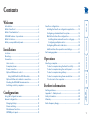
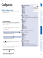
1
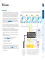
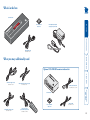
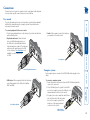
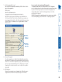
CCS4-USB Four-port keyboard and mouse switch Now with Free-Flow switching technology Locations.......................................................................................7 Mounting......................................................................................7 Connections..................................................................................8 User console.............................................................................8 Computer systems....................................................................8 Power connection....................................................................9 Optional RC4 remote control................................................10 Using the RC4 with the CCS-XB module..........................10 Optional LED monitor indicator connections......................11 Checking the CCS4-USB firmware version............................12 Switching control by computer.............................................13 Configuration Using the configuration menu..................................................14 General configuration................................................................15 Changing hotkeys..................................................................15 Mouse switching....................................................................15 Miscellaneous functions........................................................15 OPTIONS port speed..............................................................15 Operation Selecting a computer.................................................................24 To select a computer using the Free-Flow utility.................24 To select a computer using the control panel.....................24 To select a computer using hotkeys.....................................25 To select a computer using the mouse buttons...................26 To lock access to the computers...........................................27 Further information Getting assistance.......................................................................28 Appendix 1 – Cable pin-outs......................................................29 Safety information.....................................................................30 Warranty.....................................................................................30 Radio Frequency Energy............................................................31 configur Installation Free-Flow configuration.............................................................16 Installing the Free-Flow configuration application.............16 Configuring a standard Free-Flow system............................16 Multi-Monitor Free-Flow configuration...............................18 Installing drivers and multi-monitor config app.............18 Configuring multiple monitors........................................19 Configuring LED monitor indicators.....................................20 Additional Free-Flow operations and settings.....................21 Performing upgrades.................................................................22 Introduction..................................................................................2 What is Free-Flow?.......................................................................3 What is True Emulation?..............................................................4 CCS4-USB features - top and rear................................................5 What’s in the box.........................................................................6 What you may additionally need................................................6 Welcome Contents 1 Welcome The video displays are connected directly to their respective systems as usual. A single USB link (plus an optional speaker connection) is made between each system and the CCS4-USB switch. PC2 PC3 PC4 CCS4-USB switch COMPUTER K/M SPK USB1 USB2 MODE www.adder.com 4 Free-Flow An innovative in-built utility that allows the unit to automatically switch between channels by monitoring the mouse pointer position. USB 1 configur PC1 The CCS4-USB (Command and Control Switch, four port, USB) is a compact unit created to allow a single operator to access information and control operations across numerous systems and screens. With the CCS4-USB switch, you can use a single USB keyboard and USB mouse to fulfil functions that previously required four separate sets. This provides immediate savings in both desk space and also the time required to access and control up to four systems and screens. The CCS4-USB features our True Emulation technology, which ensures that the full characteristics of the connected USB keyboard and mouse are passed to every system. In addition to switching the keyboard and mouse, the CCS4-USB can also share a set of speakers and two separate USB peripherals between the four systems. This can be done either in concert with the keyboard and mouse (and each other) or totally independently. The CCS4-USB switch can be used in combination with various Adder extender products (such as AdderLink Infinity, X50 and X-DVIPRO) to extend the distance between the user and the computers under control. Switching between the systems connected to the CCS4-USB can be achieved in five different ways: • The innovative Free-Flow automatic switching utility, • The COMPUTER button on the top panel, • Keyboard hotkey combinations, • Mouse button combinations, • The optional remote control selector. welcome Introduction 2 1 The optional remote control allows the CCS4USB switch to be neatly concealed amongst the cabling. USB 2 The keyboard/mouse, the speakers and two individual USB channels can be collectively or separately switched through to each PC system. These are electronically switched to the required system using any of five methods: Free-Flow utility, CCS4-USB switch control panel, keyboard key-presses, mouse buttons or optional remote control. 3 Where additional feedback is required as to which systems and screens are selected at any time, the optional CCS-XB kit provides discreet stick-on LED monitor indicators. When a system/screen is selected, a corresponding LED monitor indicator illuminates (in a choice of colours) to confirm the action. 2 Free-Flow consists of special code within the CCS4-USB switch plus an intuitive graphical configuration application. First you inform the Free-Flow configuration application how many screens you have, their pixel resolutions and how they are physically arranged (e.g side-by-side, vertical stack, square formation, etc.). You then download this information to the CCS4-USB switch and this is used during operation to determine the precise moment to switch from one screen/system to the next. The beauty of Free-Flow is its simplicity of configuration and operation. Once the initial configuration has taken place, all monitoring and switching is handled within the CCS4-USB without need for extra connections or software utilities. More information • Free-Flow configuration • Multi-Monitor Free-Flow configuration • Operation: Selecting a computer configur Free-Flow now also supports multiple monitors on each PC (drivers are required). Issues when using Free-Flow • The CCS4-USB switch must have a minimum of firmware version 2.00 installed to operate with Free-Flow. See Performing upgrades for details. • When computers and their displays are not currently selected, the CCS4USB ‘parks’ their mouse pointers in the bottom right corner of the screen. In most cases this will cause no issues, however, it may be noticeable in circumstances such as the following: • If the task bar is set to auto hide and it is positioned either along the bottom of the screen (as default) or along the right hand side, then the task bar will automatically reappear when the mouse pointer is parked. • When playing full screen video, the on-screen controls (play, pause, seek etc.) will very likely be revealed when the mouse pointer is parked. • To cure the either of the above issues, it is possible to alter the mouse parking position. • The mouse will not flow across the screens while any mouse buttons are pressed down - this prevents undesired behaviour when dragging windows around or group-selecting items. • By default, Linux operating systems use relative mouse data which FreeFlow cannot use. A ‘udev rule’ is available that allows Linux to use absolute mouse positioning, thus enabling standard Free-Flow (not Multi-Monitor mode) to operate. • Multi-Monitor Free-Flow is for use with the Windows operating system only and requires specialist driver to be installed on each PC. See Multi-Monitor Free-Flow configuration for details. The Adder Free-Flow represents true innovation in KVM switching. For the first time, Free-Flow allows users to automatically switch between target computers simply by moving the mouse pointer from screen to screen. What makes this such a revolution is that you no longer need software to be installed on your mission critical computers in order to do this. Adder Free-Flow resides on the switch itself, sensing screen boundaries and instantaneously switching keyboard and mouse to the defined target computer. Free-Flow can be configured for almost any combination of screens using the included application which allows you to declare the individual screen sizes and visually position each one relative to the others. welcome What is Free-Flow? 3 Emulated USB switching The issues with interpreting the complex USB data streams and recreating (or Emulating) the identity of attached USB devices were eventually solved, leading to the creation of the Emulated USB switch. A neat side effect of the technique used is that each computer can be fooled into thinking that the USB device is permanently connected to it, even when the device is switched to another computer. This means that the enumeration process for the USB device takes place only once, during the first power on. After that, a computer merely sees a dormant version of the USB device whenever the device is actually connected to a different computer. However, it remains a complex task to dynamically assume the identity of a USB device, distribute it among the connected computers and maintain all of the necessary signals, states and processes. Therefore, manufacturers have previously relied upon a fixed keyboard and mouse profile that is declared to each computer, regardless of the actual connected devices. This precluded the use of any special keyboard or mouse features over and above the standard layouts. configur Enumerated USB switching The earliest attempts to switch USB devices applied a relatively ‘hands off’ approach. Enumerated USB switches are the electronic equivalent of those old mechanical KVM switches with a large knob on the front. Enumerated switches are so called because a connected USB device will be required to perform a full initiation (a process called Enumeration) every time it is switched; just as if you had pulled out the plug and then reconnected it. Enumerated switches simply pass all signals straight through between the USB device and the computer, they do not attempt to interpret any data. For most devices, this offers an advantage because the switch just leaves them to get on with their jobs without any interference or any hit on performance. However, it means that a USB keyboard or mouse cannot be used to control the switching process - a quick and simple control method expected by most users. Reliability of switching is also an issue that has plagued enumerated switches, especially when used with certain USB devices and particular operating systems. True Emulation Mindful of the limitations associated with the USB USB OTHER USB DEVICE previous USB switching techniques, we set about KEYBOARD MOUSE creating a more effective and elegant solution. After a great deal of research and development, HOST True Emulation is the result. CONTROLLER True Emulation allows the complete identity of the keyboard and mouse to be copied and then presented to all of the connected computers. EMULATION ENGINE This means that any keyboard offering specialist function keys or any mouse with extra features will be fully supported at each computer. As with the previous emulation method, the unselected computers will continue to see the identities USB USB USB USB HUB HUB HUB HUB of the keyboard and mouse, which means that no enumeration is necessary when their link becomes active once again. This not only helps PC PC PC PC to speed up the rate of reconnection, but also 1 2 3 4 raises the reliability of switching because USB links are at their most vulnerable during the The emulated section of enumeration process. the switch is shown in True Emulation relies upon a high speed circuit, blue and handles only the called an Emulation Engine, to fully emulate keyboard and mouse. The the USB device identities and also interpret green enumerated section keyboard and mouse data streams. The result is full support for KVM switching control via hotkey of the switch handles other presses or the third button/scroll wheel of a USB devices and also uses mouse. the USB hubs to link with True Emulation is not necessarily required by the computers. other USB devices, which is why you will also find two enumerated circuits included (shown in green within the block diagram) alongside the True Emulation feature (shown in blue). This allows those other USB devices to operate at their highest speeds, without any intervention. The enumerated circuits benefit greatly from the USB Hubs that are jointly used with the True Emulation system. Because they interface directly and permanently with each computer, they help to stabilise the dormant links, making errors during enumeration much less likely. The dual switching arrangement provides further flexibility because the True Emulation and enumerated sections can be switched in unison or independently of each other, as required. Thus, your various peripherals can operate with different computers at the same time. Please see software release notes for a list of supported products. True Emulation represents a significant breakthrough in sharing USB devices between two or more computer systems. Until this point, the problem has been how to create a USB switch that provides all of the following: • Quick, transparent and reliable switching, • Accurate representation of the connected USB keyboard and mouse, • Switching control via the connected USB keyboard and/or mouse. The difficulty in achieving all of the above requirements has been due to the complexity of the USB standard. This has led to various problems that have spawned a number of possible solutions. welcome What is True Emulation? 4 CCS4-USB features - top and rear K/M SPK USB1 USB2 MODE www.adder.com COMPUTER button Press to change to the next computer channel. MODE button Press to determine which peripherals should be switched to another computer channel (will occur when the COMPUTER button is pressed. Indicators The upper four indicators scroll across in sequence when the Free-Flow utility is engaged. The lower four indicators (K/M, SPK, USB1, USB2) show which peripherals are switched to the current computer channel OR (as you begin pressing the MODE button) the peripherals that will be switched during the next press(es) of the COMPUTER button. The seven segment numeric display indicates the computer channel that is currently active. •LED monitor indicators - the optional CCS-XB module links to here and provides multiple light up monitor indicators. • Upgrades - used to update the internal firmware when necessary by connecting to a computer. 4 INDOOR USE O N LY 3 2 1 5V 2.5A OPTIONS Power input The power supply connects here. User console Connect a USB keyboard and mouse plus optional speakers to these connectors. Computer channels Each computer connects to one of these four channels via a USB B-type connector and an audio 3.5mm jack input. User console Connect up to two USB devices to these connectors. These ports are switched in an enumerated manner (see What is True Emulation?) Options port This 10p10c port can separately support the following functions: • Remote control - allows a standard Adder RC4 four button remote control unit to be used to switch channels (see Optional RC4 remote control for details). configur COMPUTER welcome The CCS4-USB switch is housed within durable, metallic enclosure with all connectors situated at the rear panel. The smart top panel features the control buttons and the operation indicators. 5 What’s in the box Power adapter (12.5W) and country-specific power lead Flash upgrade cable Part number: VSC40 What you may additionally need B X SC C Optional CCS-XB LED monitor indicator kit Audio cable 2m (3.5mm stereo jacks) Part number: VSC22 m LED monitor indicator x 4 Part number (each): CCS-LED o .c er dd .a w w w USB cable 2m (type A to B) Part number: VSC24 CCS-XB controller AD DE R 4 Four self-adhesive rubber feet 3 2 Standard 3m CAT5 patch lead Part number: VSC23 RC4 remote control plus standard 3m patch lead Part number: RC4-8P8C configur Four self-adhesive rubber feet welcome CCS4-USB switch CATx link cable Part number: VSC46 1 om der.c w.ad ww 6 Installation welcome installation configur Before you begin connecting to the keyboard, mouse and source systems, it is advisable to mount the CCS4-USB switch in place, either: • On a horizontal surface using the supplied self adhesive feet, or • Amongst the cabling at the rear of the desk. Please consider the following important points when planning the position of the CCS4-USB switch: • Situate the CCS4-USB switch close to the systems to which it will be connected and near to a source of mains power. • Thanks to the optional remote control and/or Free-Flow, the CCS4-USB switch can be situated out of sight within the cabling cradle of a desk or placed adjacent to the connected systems. • Consult the precautions listed within the Safety information section. Mounting Locations 7 Connections Connections do not need to be carried out in the order given within this guide, however, where possible connect the power in as a final step User console 4 Audio: Where required, connect the lead from your speakers to the audio socket. IN installation DO US OR ON E LY 5V 2.5 A IN DO US OR ON E LY 5V 2.5 A OP TIO From speakers TIO NS From USB keyboard and mouse Computer systems Each computer system is connected to the CCS4-USB switch using (up to) two cables. 3 USB devices: Where required, attach the leads from your USB peripherals to the USB sockets labelled USB1 and USB2. From USB peripherals 1 To connect a computer system 1 Ensure that power is disconnected from the CCS4-USB switch and the system to be connected. 2 Use a USB cable (type-A to type-B) to link a USB 2 port on the computer system to the USB port of the required channel on the rear of the switch. 1 3 If required, use a stereo audio link cable (3.5mm jacks at either end) to link the speaker port on the computer system to the audio port of the required channel on the rear of the switch. USB and audio links to a system OP configur NS To connect peripherals to the user console 1 Position your peripheral devices in the vicinity of the switch such that their cables will easily reach. 2 Keyboard and mouse: Attach the leads from your USB keyboard and mouse to the USB sockets specifically labelled with keyboard and mouse symbols. The keyboard and mouse will operate in any of the USB sockets, however, True Emulation is not available on sockets labelled USB1 or USB2. welcome The ports that make up the user console are where you attach the peripherals which will be shared between the computer systems. Ensure that power is disconnected from the switch. 8 Power connection 2 Connect the IEC connector of the supplied country-specific power lead to the socket of the power adapter. IN DO US OR ON E LY 5V 2.5 TIO NS 3 Connect the power lead to a nearby main supply socket. Note: Both the switch and its power supply generate heat when in operation and will become warm to the touch. Do not enclose them or place them in locations where air cannot circulate to cool the equipment. Do not operate the equipment in ambient temperatures exceeding 40 degrees Centigrade. Do not place the products in contact with equipment whose surface temperature exceeds 40 degrees Centigrade. OP configur installation A To connect the power supply 1 Attach the output lead from the power adapter to the 5V socket on the rear panel of the switch. welcome The CCS4-USB switch is supplied with a 12.5W power adapter. There is no on/ off switch on the switch, so operation begins as soon as a power adapter is connected. 9 Optional RC4 remote control 4 3 2 1 B X S- C C 2 Connect the other end of the cable to the OPTIONS port on the rear panel of the switch. IN DO US OR ON E LY The RC4 remote can now be used in the usual manner to select the required channels. Note: If any reprogramming of the CCS4-USB is required, you will need to temporarily disconnect the RC4 unit to allow the computer to be reattached. 5V 2.5 A OP TIO NS configur Patch cable Adder P/N: VSC23 (Included in RC4-8P8C kit) installation To connect the remote control to the CCS-XB module 1 Once you have used the Adder FreeFlow utility to program the CCS4-USB switch (see the section Configuring LED monitor indicators), unplug the flash upgrade cable from the TO KEYPAD OR PC port of the CCS-XB module. 2 Use the patch cable supplied with the RC4 kit to link the RC4 to the TO KEYPAD OR PC port of the CCS-XB module. To connect the remote control 1 Connect either end of the supplied cable to the socket at the rear of the RC4 remote control. When the optional CCS-XB LED monitor indicator module is used with the CCS4-USB switch, it requires permanent use of the latter’s OPTIONS port which would otherwise be used to attach the RC4 remote. However, the CCS-XB module has an output port that provides a link through to the OPTIONS port (to which it is connected) that can be used to attach the RC4 remote. The optional RC4 remote control unit (full part number: RC4-8P8C) can be used to provide direct push button access to any channel from your desktop. The RC4 remote control is supplied with a 3 metre cable that is used to link with the OPTIONS port on the rear panel of the switch. welcome Using the RC4 with the CCS-XB module 10 Optional LED monitor indicator connections 2 Link each LED monitor indicator to a port on the CCS-XB module - ports 1 to 4 are most commonly used. C C X S- Port 3 A Adder CCS-XB module configur Each indicator has a self adhesive Velcro tab to assist with mounting on your video displays. NS TIO OP 5V Port 4 Connect to a vacant serial port on your computer B X S- C C Link cable Adder P/N: VSC46 (Included in CCS-XB kit) w w r e dd .a w Note: If required, the PC connection can be removed once programming is complete. Flash upgrade cable Adder P/N: VSC40 (Included in CCS4USB kit) LED monitor indicator with 3 metre lead installation dd .a w w Port 2 3 You need to tell the CCS4-USB which LED monitor indicator to illuminate (and in which colour) for each channel. To do this connect your computer to the TO KEYPAD OR PC port of the CCS-XB module (while it remains connected to the CCS4-USB switch). Please see the section Configuring LED monitor indicators. 4 Apply power to the switch. ER E US NSOL CO OR DO IN SE U Y L ON 2.5 w Insert the lead for the first indicator into port 1 To connect the CCS-XB module and monitor indicators 1 Remove power from the switch. Use the flat cable supplied with the CCS-XB kit to link the module to the OPTIONS port of the CCS4-USB switch. Note: If the optional RC4 remote control is connected to the OPTIONS port, remove this first. It can be attached to the CCS-XB module later (see here). 4 Adder CCS4-USB switch welcome B The optional CCS-XB module enables you to add LED (Light Emitting Diode) monitor indicators to each of your video display screens to show which are active. Note: The CCS4-USB switch requires firmware version 2.0 or later to be installed. Please see here for details about how to check. The optional CCS-XB module connects to the OPTIONS port of the main CCS4USB switch. Each individual LED monitor indicator then connects to one of the ten ports on the CCS-XB module. Notes: The CCS-XB module MUST be connected before the switch is powered on, otherwise the module will not be recognised. Also, if the module is temporarily disconnected from the switch during operation, communication between the two will cease and the switch will need to be re-powered with the CCS-XB module attached. Before operation of the LED indicators can occur, it is necessary to temporarily connect the CCS4-USB switch to a Windows computer. This will allow you to use the Adder Free-Flow application to program the required operation of the switch. Please see Configuring LED monitor indicators for details about using the Adder Free-Flow configuration application. 11 installation configur In order to operate correctly with the CCS-XB, it is important that your CCS4USB has firmware version 2.0 (or greater) installed. If in doubt you can check the firmware version of your CCS4-USB as follows: 1 With your CCS4-USB powered on and with a USB keyboard attached, press and hold the COMPUTER button for roughly six seconds until the display shows C. 2 On the connected keyboard, press F followed by 1 and then press Enter. The digits of the firmware version will be shown in sequence with a short pause between each. For instance 1 > 0 > 2 means that the firmware version is 1.02 and requires an upgrade. 3 Press E and then press Enter to return the CCS4-USB to normal operation. If your CCS4-USB unit does require a firmware upgrade, please refer to the Performing upgrades section. welcome Checking the CCS4-USB firmware version 12 The cable link from the computer needs to connect the transmit (TXD) line of the computer to the receive (RXD) input of the CCS4-USB and also link the ground terminals (GND) of the two devices. See Appendix 1 for details. To connect a computer remote control 1 Use the supplied flash upgrade cable to link the OPTIONS port on the rear panel of the CCS4-USB switch and a vacant serial port on the computer. Serial port parameter settings Ensure that the chosen serial port is configured to the following: • Baud rate: 1200 • Data bits: 8 • Stop bit: 1 • Parity: None Channel selection codes IN DO US OR ON E LY • • • • 5V 2.5 A Channel 1: Channel 2: Channel 3: Channel 4: ASCII Character HexDecimal ‘1’ ‘2’ ‘3’ ‘4’ 0x31 0x32 0x33 0x34 49 50 51 52 installation Connecting a computer for remote control configur The OPTIONS port allows an external serial input, typically from a computer, to control the selection of the various channels. You can use either the supplied flash upgrade cable (part number VSC40) or alternatively construct a custom cable to link the CCS4-USB switch and the computer. For pin-out details of the custom cable, see Appendix 1. Upon receipt of the correct code, the CCS4-USB will switch immediately to the appropriate channel. welcome Switching control by computer OP TIO Note: If the optional CCS-XB module is used with the CCS4-USB, connect the computer instead to the TO KEYPAD OR PC port on the CCS-XB module. NS 13 To use the configuration menu During normal use, the seven segment display on the control panel shows the number of the currently selected computer channel. From this condition, enter configuration mode as follows: 1 Press and hold the control panel COMPUTER button for roughly six seconds. The display will show: Enter the Hotkey menu Ctrl + Alt Ctrl + Shift Alt + Shift Right Alt Alt Left Ctrl + Alt Right Ctrl + Alt Hotkeys disabled Set a new password for use with the lock mode 2 On the keyboard, press the letter key for the required menu section, e.g. The display will show the pressed letter, e.g. 3 Press the number of the required setting, e.g. The display will show the pressed number, e.g. 4Press to accept the setting and return to the main menu section. The display will show: 5 You can now continue with your next configuration change (go to step 2), or exit from the configuration menu (see below). To exit the configuration menu and save changes • Press and then press to exit and save changes. To exit the configuration menu without saving • Press either of the front panel buttons. Enter the Switch Mode menu All K/M + Speaker K/M only Speaker only USB1 only USB2 only Enter the User Preferences menu Enable mouse switching Disable mouse switching Cycle all ports (when using ‘Hotkey + Tab’ or ‘Autoscan’) Cycle only active ports (when using ‘Hotkey + Tab’ or ‘Autoscan’) installation Enter the Functions menu Show current firmware version Reset configuration to factory defaults ( is displayed momentarily) configur The configuration mode allows you to determine numerous aspects of the CCS4-USB switch capabilities. You can press at any point to exit from an option and return to the main menu ( ) section. Using the configuration menu Set the OPTIONS port baud rate 1200 2400 9600 19200 38400 57600 115200 Configuration 14 General configuration You can enable or disable mouse switching to suit your installation requirements. To enable/disable mouse switching 1 Enter the Configuration menu. 2 Press to enter the User Preferences menu and then press either: to Enable mouse switching to Disable mouse switching 3Press to accept the setting and return to the main menu section. 4Press and then to exit the menu and save changes. OPTIONS port speed You can change the speed of the OPTIONS serial port. To change the OPTIONS port speed 1 Enter the Configuration menu. 2 Press to enter the Hotkey menu and then press either: to choose 38400 to choose 1200 to choose 57600 to choose 2400 to choose 9600 to choose 115200 to choose 19200 3Press to accept the setting and return to the main menu section. 4Press and then to exit the menu and save changes. . The display will show momentarily. 4 Press and then to exit the menu and save changes. To show the current firmware version 1 Enter the Configuration menu. to enter the Functions menu 2 Press 3Press . and then The display will blank for a short while and then the major number of the firmware revision will be shown. The display will blank again and then show the first digit of the minor number. Following another blank, the second digit of the minor number will be displayed. e.g. <blank> 1 <blank> 0 <blank> 2 <blank> equals v1.02 4 Press and then to exit the menu and save changes. To set a new password 1 Enter the Configuration menu. 2 Press and then . The display will show 3 Enter a new password and then 4 Press and then . See To lock access to the computers. to exit the menu and save changes. installation and then configur Mouse switching 3Press To change the hotkeys 1 Enter the Configuration menu. 2 Press to enter the Hotkey menu and then press either: to choose Alt to choose Ctrl + Alt to choose Left Ctrl + Alt to choose Ctrl + Shift to choose Right Ctrl + Alt to choose Alt + Shift to disable the Hotkeys to choose Right Alt 3Press to accept the setting and return to the main menu section. 4Press and then to exit the menu and save changes. To reset configuration to factory defaults 1 Enter the Configuration menu. 2 Press to enter the Functions menu CCS4-USB switches use and as their standard hotkeys. These can be changed if they clash with other software or hardware within the installation. Miscellaneous functions Changing hotkeys 15 (Windows PC required) Note: By default, the Free-Flow screen will automatically add four screens in a straight row ( 1A 2A 3A 4A ), each at a resolution of 1920 x 1080. You can edit or delete these screens as required. 2 Arrange the coloured rectangular screen representations to mimic the physical layout of the actual displays, for example: 1A 2A 3A 4A 1A 2A 3A 4A 1A 2A 3A 4A The important thing is to define where each screen edge abuts to the next so that the CCS4-USB switch can determine the correct moments to switch channels. Use the small black squares around the perimeter of each highlighted screen representation to change their size or stretch them. Note: The numbering of the screen representations relate directly to the four channels on the CCS4-USB switch. e If required, test the connection. Select Configure > Send Layout to Switch. If no error message is returned then you can assume the connection is working. installation Use the Free-Flow application to declare the display screens and their positions relative to each other. Then download the configuration to the CCS4-USB switch. 1 On the icon bar, click the red, green, blue and yellow screen icons (or use the Screens menu) to add the required number of display screens to the map area: continued configur The Free-Flow configuration application is available for download from the Adder website (www.adder.com). 1 Install the application onto any computer (not necessarily one of the four computers linked to the CCS4-USB switch) that has a vacant serial port. Run the installation application and follow the on-screen instructions. 2 Use the supplied flash upgrade cable (VSC40) to link the computer serial port to the CCS4-USB OPTIONS port. If the optional CCS-XB module is connected to the OPTIONS port, then instead connect the upgrade cable between the computer serial port and the TO KEYPAD OR PC port of the CCS-XB module (see Optional LED monitor indicator connections for details). 3 Run the installation application and follow the on-screen instructions. Once installed, start the Free-Flow application. It may report that it is ‘Unable to communicate with the device’. If so: a Click the OK button, whereupon the Free-Flow window will open. bSelect Configure > Connection... to display the Communication configuration dialog. c In the first tab, select the Serial connection. The Network option is used only for the CCS-PRO4 switch. d In the Serial tab, check that the COM port setting matches the serial port on your computer to which the CCS4-USB switch is connected. The switch’s standard baud rate is 1200. Configuring a standard Free-Flow system Installing the Free-Flow configuration application Free-Flow configuration 16 Se Fre an 3 Double-click on each screen representation to set the screen resolution and, optionally, add a screen name and/or configure an LED monitor indicator: configur The screen resolutions are not critical but they enable the CCS4-USB switch to accurately map the movement of the mouse onto corresponding movements of the pointer across the screens. The screen names, if used, are not downloaded to the CCS4-USB switch. If you need to configure an LED monitor indicator, click the LED Setup tab. Please see Configuring LED monitor indicators for details. 4 When the screen map is complete and accurately matches the true layout of the display screens, click File and choose the Save option to store a copy of the layout. The layout will be stored as a ‘Free-Flow Config file’ with the extension: .ffc 5 Ensure that the optional upgrade cable is correctly installed - see Installing the Free-Flow configuration application. 6 To send the configuration, click the Configure menu and choose the Send Layout to Switch option. • If the download is successful, the screen representations will briefly turn grey and the upper four indicators on the CCS4-USB switch will begin to scroll across (they will continue to do this while Free-Flow mode is enabled). • If the download is unsuccessful, a message dialog will explain that it is ‘Unable to communicate with the device’. Check the upgrade cable, check that the correct serial port is selected and check that the connection speed shown within the utility matches that of the CCS4-USB switch. installation See also Additional Free-Flow operations and settings 17 Multi-Monitor Free-Flow configuration (Windows only) Installing drivers and multi-monitor config app 2 The options available during installation are as follows: • Full Install, (this is recommended), or • Options to install individually: • Configuration App. This is the Free-Flow application and needs to be installed only on the PC that will be used to set up the CCS4-USB switch via the supplied flash upgrade cable (VSC40) and OPTIONS port. • Visual C++ Runtime The C++ runtime library is a windows component that is required by the multi-monitor driver in order to run its helper applications. It is pre-installed with Windows but is offered here as an option as you may want to keep an older version already installed on your system, or you may already have a newer version in your copy of Windows. • Drivers. Multi-Monitor Free-Flow drivers that are required on each PC that will be using Multi-Monitor. Note: The Install for all users option should be ticked if there are more than one user account on the PC and all need to use Free-Flow. Choose the required components and click the Next > button. 3 Once the chosen components have been installed, click the Finish button. Note: On the PC that will be used to set up the CCS4-USB switch, you can optionally tick ‘Click to run the Free-Flow Configuration Application’ in the lower left corner to immediately begin using Free-Flow - see Configuring multiple monitors on the next page for details. configur installation In order to use Multi-Monitor mode you will need to install a Multi-Monitor Free-Flow driver (available for download from the Adder website www.adder. com/products/adder-freeflow#downloads) onto each PC that has multiple monitors attached. 1 On each multiple monitor PC, run the downloaded file. After accepting the licence agreement you will be prompted to choose a destination folder. Either accept the suggested location or change it, as necessary. Note: On each PC that you installed the driver, a process called mumoapp.exe will remain running. 18 installation configur 4 Arrange the coloured rectangular screen representations to mimic the physical layout of the actual displays. For example, you may wish to have the two screens of PC1 side by side, with the two screen screens of PC2 below them (as shown left), or some other arrangement to reflect the actual positions of the physical monitor screens. The important thing is to define where each screen edge abuts to the next so that the CCS4-USB switch can determine the correct moments to switch channels. Use the small black squares around the perimeter of each highlighted screen representation to change their size or stretch them. Note: The numbers of the screen representations relate directly to the four channels on the CCS4-USB switch, while the letters relate to the screen hierarchy attached to any single computer (i.e. A is primary, B is secondary, etc.). 5 Continue from step 3 of the standard Free-Flow configuration instructions. Multi-Monitor configuration is similar to normal Free-Flow setup except that you can add more than one display per PC, up to a total of eight per machine. Note: It is necessary to install a driver on each PC that has multiple displays - see Installing drivers and multi-monitor config app on the previous page. 1 Use the supplied flash upgrade cable (VSC40) to link the computer serial port to the CCS4-USB OPTIONS port. If the optional CCS-XB module is connected to the OPTIONS port, then instead connect the upgrade cable between the computer serial port and the TO KEYPAD OR PC port of the CCS-XB module (see Optional LED monitor indicator connections for details). 2 If it is not already running, start the Free-Flow configuration application. 3 On the icon bar, click the red, green, blue and yellow screen icons (or use the Screens menu) to add the required number of display screens per computer to the map area. For example, to add two monitors for PC 1, click the red computer icon twice. The two red monitor representations will be placed side by side within the Free-Flow map area. Configuring multiple monitors 19 Configuring LED monitor indicators When the optional CCS-XB LED monitor indicator kit is used, there are several configuration options available that allow you to customise behaviour and these are set using the Free-Flow configuration application. 3 For a newly added screen the LED: entry will show No LED. Click on the drop down handle and choose the LED indicator that you wish to associate with the currently selected video display screen: To adjust details for an individual indicator 1 Double-click on a screen representation (or right click on a screen representation and then choose Properties) to display the screen popup. 2 Click the LED Set-up tab to display the indicator details: Note: Each LED indicator can only have one colour, so if you associate an indicator with more than one screen and then change the colour on a later screen assignment, it will be changed for all the screens in the list for that LED indicator. 6 Click OK to save and exit. 7 Repeat steps 1 to 6 for each screen that requires an LED monitor indicator. 8Choose Configure > Send Layout to Switch to update the CCS4-USB switch. 9 IMPORTANT: Once the Free-Flow configuration application has downloaded the setup, remove and reconnect power to the CCS4-USB to allow the new settings to take effect. installation configur 4 Choose the CCS-XB LED output port that you wish to associate with the currently selected video screen. 5 Optionally alter the colour, from the Colour: list, that you wish the LED indicator to display when the associated video screen is selected: For each installed video display screen, you have the opportunity to add and configure an LED monitor indicator. Note: It is possible to associate any LED indicator with more than one video screen. Adjusting individual indicators Each entry within the LED: list relates to one of the ten output sockets on the CCS-XB module. www.adder.com To impose a default colour on all connected indicators, choose the required Default colour and then tick the option Set all LEDs to this colour. Use the Default brightness option to determine the intensity of all indicators. Click OK to exit and apply the required settings. Note: Once default settings have been made you can optionally change any or all indicators individually as required using the steps outlined below. CCS-XB If necessary, you can impose default colour and brightness settings upon all connected LED monitor indicators. Choose the Configure > LEDs... menu item to display the following popup: Adjusting colour and brightness for all indicators 20 Additional Free-Flow operations and settings In addition to the core configuration functions, Free-Flow has a number of additional settings that you can make. Switch... settings Acceleration Mouse acceleration allows you to move the mouse pointer quickly across the large areas of the screen in response to small but sharp shifts in the mouse position. The Configure > Mouse... option provides settings between 0 and 50, however, a value of 12 to 15 will give a typical Windows-like default operation. Enable (Disable) Free-Flow This option allows you to switch off the Free-Flow feature within the CCS4-USB switch. Located within Configure > Switch... menu item, untick the Enable Free-Flow checkbox and download the configuration the CCS4-USB switch to disable. Mouse parking... setting Start-up Port Located within Configure > Switch... menu item (see above image), this option allows you to determine which port should be enabled whenever the CCS4-USB switch is first powered on. Mouse parking allows you to optionally determine where the mouse pointer for each system should be placed when the focus moves to a different system/ video screen. The Configure > Mouse parking... option displays vertical and horizontal scroll bars. Use the scroll bars to pinpoint the position that should be used to park the dormant mouse on each screen. configur Switch Mode Located within Configure > Switch... menu item (see above image), these check boxes allow you to determine which peripherals should be switched whenever the channel is changed by the Free-Flow method. The switching of peripherals via the other methods of channels selection (e.g. the front panel, hotkeys, mouse buttons, etc.) remain unaffected by these settings. By default, the Keyboard/Mouse and Audio are selected. installation Mouse... (acceleration) setting 21 (Windows only) 5 - Run the KVM Firmware Uploader utility From that folder, select the KVMUploader icon to run the upgrade utility. The KVM Firmware Uploader dialog will be displayed: configur installation To use the KVM Firmware Uploader utility 1 - Obtain and run the KVM Firmware Uploader. Download the latest CCS4-USB switch KVM Firmware Uploader from the Adder Technology website and install it on a Windows-based upgrade computer that will be connected to the CCS4-USB switch. The files are supplied as a compressed ZIP file. Decompress the ZIP file with an appropriate tool such as WinZip (www.winzip.com) and copy all contained files to the same folder on the upgrade computer. 2 - Power off the CCS4-USB switch Remove the power supply plug from the rear panel of the switch. 3 - Connect the upgrade computer to the CCS4-USB switch Connect the supplied flash upgrade cable between the serial port of the Windows-based computer and the OPTIONS port on the rear panel of the switch. IN DO US OR ON E LY 5V 2.5 A OP TIO NS There is no need to adjust the computer’s serial port settings as the application will do this automatically. Items required to perform an upgrade • The supplied flash upgrade cable (VSC40). • A Windows-based computer with an RS232 serial port. • The latest version of the KVM Firmware Uploader and firmware files for the CCS4-USB switch - available from the Technical Support > Updates section of the Adder Technology website (www.adder.com). 4 - Invoke upgrade mode While powering on or when already powered: Press and hold the COMPUTER and MODE buttons (for up to ten seconds) until the numeric indicator shows ‘ ’. 6 - Query the CCS4-USB switch Click the Query Unit button to confirm that communication is possible with the CCS4-USB switch and to establish its firmware details. If successful, the ‘Unit connected’ field should show the name of the CCS4-USB switch and the current firmware will also be listed. If the application cannot contact the CCS4-USB switch, re-check the connection cable and click the Advanced... button to check that the correct serial port is being used. Change the serial port within the Advanced... section, if necessary. continued The CCS4-USB switch is fully upgradeable via flash upgrade. Such upgrades require a Windows-based computer system to be linked via the OPTIONS port. Performing upgrades 22 8 - Commence the upgrade To begin the upgrade process, click the Upload Now button and confirm when requested. The progress will be shown within the dialog. Should you decide not to continue with the upload at any stage, click the Abort button; response to this is usually immediate, however, during an erase command, the upload will not be aborted until the erase is complete (this may take a few seconds). 9 - Cycle the power Disconnect the power and remove the upgrade cable. When the power is re-applied the CCS4-USB switch will operate using the new firmware. installation configur Check also that the ‘New firmware version’ is greater than the ‘Current firmware version’. Check that the ‘Intended Target Units’ field matches the ‘Unit Connected’ field. Issues to consider when performing flash upgrades The upgrade program rewrites the internal firmware code. If the upgrade process is interrupted then the switch will have invalid code and will not be able to operate. It is therefore good practice to ensure that the upgrade process is always fully completed. A partial or failed upgrade may be rectified by performing another upgrade. WARNING: Running faulty or partially upgraded code may have unpredictable results and may damage your CCS4-USB switch or computing equipment. 7 - Select the upgrade file to be used From the main KVM Firmware Uploader dialog, click the Browse... button and select the upgrade file: CCS4U_xxx.txt where xxx is the firmware version. The upgrade file details will be displayed within the dialog. IMPORTANT: Check that the ‘Intended Target Units’ field matches the ‘Unit Connected’ field. If these fields do not match then you may have an incorrect upgrade file, check with Adder Technology Ltd before proceeding. Check also that the ‘New firmware version’ is greater than the ‘Current firmware version’. 23 Operation Selecting a computer Use this button to choose which peripherals will be switched To select a computer using the Free-Flow utility • Simultaneously press and hold and , then press K/M SPK USB1 USB2 MODE The K/M, SPK, USB1, and USB2 indicators show which peripherals are switched to the current computer channel OR (as you begin pressing the MODE button) the peripherals that will be switched during the next press(es) of the COMPUTER button. 1 Optional: If you need to selectively switch some of your peripherals, press the MODE button repeatedly to change the switching mode: K/M SPK USB1 USB2 MODE Will switch all peripherals together MODE Will switch keyboard, mouse and speakers MODE Will switch only the keyboard and mouse MODE Will switch only the speakers MODE Will switch only USB peripheral 1 Will switch only USB peripheral 2 Notes: If an indicator flashes, it signifies that the respective peripheral is currently switched to another computer channel. The peripherals to be switched using the Free-Flow method are set independently 2 Press the COMPUTER button repeatedly to select the required computer channel. Use this button to choose the next required computer COMPUTER Once configured, Free-Flow allows you to change channels merely by moving the mouse to edge of one screen towards the next screen. As the mouse pointer reaches the edge it will cause the channel to automatically change and will jump to the next screen. Notes: Free-Flow cannot be enabled until a layout has been configured and downloaded to the CCS4-USB switch - see Free-Flow configuration. The mouse will not flow across the screens while any mouse buttons are pressed down - this prevents undesired behaviour when dragging windows around or group-selecting items. You can determine which peripherals will be switched by Free-Flow independently of those that would be switched with any other method. See Switch Mode within the Switch... settings section. You can continue to use any of the other channel switching methods while Free-Flow is enabled. The four upper indicators on the CCS4-USB display panel will scroll across every few seconds to show that Free-Flow is enabled. See What is Free-Flow? for an introduction to the utility or Free-Flow configuration for more details about how to prepare it for operation. You can temporarily disable (and re-enable) Free-Flow using hotkey presses: The upper four indicators will intermittently scroll across whenever Free-Flow is enabled. configur Indicates the number of the currently selected computer The control panel allows you to determine how the various peripherals are switched to one or more computer channels. There are five ways to switch the common peripherals to specific computer channels: • Using the innovative Free-Flow automatic switching utility Þ • Using the control panel • Using hotkeys • Using mouse button presses • Using the optional RC4 remote control To select a computer using the control panel 24 2 While still holding and , press the number key of the required channel address (or the TAB key), then release all of the keys. Note: The numbers on your keyboard’s numeric keypad are not valid, use only the numeral keys above the QWERTY section. The ports (K/M, audio and/or USB) that are switched using this method depend upon the switching mode that is currently set using the control panel buttons. The range of standard hotkey combinations are as follows: Note: If your hotkeys have been changed, substitute them for the examples given here. and Selects channel 1 Selects channel 2 Selects channel 3 Selects channel 4 Isolates the user console from all channels in Selects the next channel (see note ) What are hotkeys? The and keys when pressed in combination are called ‘hotkeys’ and they signal to the CCS4-USB switch that you wish to control it, rather than the computer. However, if these particular hotkeys clash with another device or program, you can change them to a different combination within the Configuration menu. 1 Simultaneously press and hold and 2 Press and release a command key: to switch all peripherals to switch only the keyboard and mouse to switch only the speakers to switch only USB1 and USB2 . 3 Press and release the required channel number ( above the QWERTY section). to using only the keys 4Release and . The appropriate peripherals will change to the chosen channel. Note: Regardless of which peripherals were switched, the front panel indicators will continue to show the switching mode that was last determined using the front panel controls. Disabling/Enabling Free-Flow Once Free-Flow is in operation, you can temporarily disable (and re-enable) it: • Simultaneously press and hold and , then press Choosing which computers are accessed when using hot keys + tab The computer channels that are visited when you use the hot keys + tab (or mouse buttons) are determined by a setting within the Configuration menu: 1 Enter the Configuration menu. 2 Press and then press either: to choose Cycle all ports, or to choose Cycle only active ports 3Press to accept the setting and return to the main menu section. 4Press and then (or other hotkeys, if altered). configur and 1 Simultaneously press and hold Additional hotkey press combinations In addition to the standard hotkey press combinations (shown left), you can also add additional keypresses in order to determine which peripherals are switched: Using hotkey combinations, you can quickly switch the keyboard and mouse, speakers and USB peripherals to any computer channel. There are two main ways to use hotkeys: Standard and Additional. Standard hotkey press combinations The standard hotkey press combinations allow you to change channels with the minimum of keypresses: To select a computer using hotkeys to exit the menu and save changes. 25 To select a computer using the mouse buttons to choose Cycle only active ports 3Press to accept the setting and return to the main menu section. 4Press and then to exit the menu and save changes. configur 2 Press and then press either: to choose Cycle all ports, or Choosing which computers are accessed when using mouse buttons The computer channels that are visited when you use the mouse buttons (or hotkeys + tab) are determined by a setting within the Configuration menu: 1 Enter the Configuration menu. To select a computer using the mouse buttons 1 Hold down the middle button (or scroll wheel) of the mouse. 2 Click the left mouse button to increment the channel number or click the right mouse button to decrement the channel. When the correct channel is reached, release the middle button. When using this method of switching: • The computer channels that are visited depend upon the configuration menu setting (see note ). • The ports (K/M, audio and/or USB) that are switched using this method depend upon the switching mode that is currently set using the control panel buttons. Using the mouse buttons, you can quickly switch the keyboard and mouse, speakers and/or USB peripherals to any computer channel. Note: These procedures work only with three-button or IntelliMouse devices and only if the ‘Mouse Switching’ option has been enabled. 26 To lock access to the computers When privacy is required, you can lock access to the connected computers via the switch. To lock the switch 2 While still holding and , press . The display will show (providing a valid password has been previously set). You will not be able to access any computers until the password is correctly entered. To unlock the switch • When prompted, enter the correct password and press . To set a new password 1 Enter the Configuration menu. . The display will show 3 Enter a new password and then . The password is not case sensitive and can be any combination of key strokes, including the function keys, but excluding the Num Lock, Caps Lock, Scroll Lock and keys. If your keyboard has special media keys, these also cannot be used as part of the password. When you have typed in your password, press to store it. Don’t worry if you type the password incorrectly, you can always re-enter configure mode and set the password again. 4 Press and then to exit the menu and save changes. To cancel the password 1 Enter the Configuration menu. 2 Press 3Press 4 Press and then . The display will show to remove the existing password. and then and then to exit the menu and save changes. If you forget the password To clear an existing password: Connect the OPTIONS port of the switch to the serial port of a computer and transmit the text clrpwd to the switch. 2 Press (or other hotkeys, if altered). and configur 1 Simultaneously press and hold 27 Further information • Technical support – www.adder.com/contact-support-form For technical support, use the contact form in the Support section of the adder.com website - your regional office will then get in contact with you. • Adder Forum – forum.adder.com Use our forum to access FAQs and discussions. configur • Online solutions and updates – www.adder.com/support Check the Support section of the adder.com website for the latest solutions and firmware updates. If you are still experiencing problems after checking the information contained within this guide, then we provide a number of other solutions: Getting assistance This chapter contains a variety of information, including the following: • Getting assistance - see right • Appendix 1 – Cable pin-outs • Safety information • Warranty • Radio frequency energy statements 28 Appendix 1 – Cable pin-outs 6 2 RXD RXD 3 3 TXD GND 2 5 GND Serial remote control and flash upgrade cable (10p10c) 10p10c connector D-Type female 9 way TXD 7 2 RXD RXD 4 3 TXD GND 3 5 GND Note: You can also use the supplied flash upgrade cable (part number VSC40). TXD configur D-Type female 9 way 8p8c connector Serial remote control and flash upgrade cable (8p8c) The OPTIONS port uses a 10p10c socket which can accommodate both 10p10c connectors as well as the much more common 8p8c connectors, which are used on Ethernet leads and patch cables. The pin-outs are listed in this section for both types of connector. 29 configur Adder Technology Ltd warrants that this product shall be free from defects in workmanship and materials for a period of two years from the date of original purchase. If the product should fail to operate correctly in normal use during the warranty period, Adder will replace or repair it free of charge. No liability can be accepted for damage due to misuse or circumstances outside Adder’s control. Also Adder will not be responsible for any loss, damage or injury arising directly or indirectly from the use of this product. Adder’s total liability under the terms of this warranty shall in all circumstances be limited to the replacement value of this product. If any difficulty is experienced in the installation or use of this product that you are unable to resolve, please contact your supplier. • For use in dry, oil free indoor environments only. • Not suitable for use in hazardous or explosive environments or next to highly flammable materials. • Warning – the power adapter contains live parts. • No user serviceable parts are contained within the power adapter - do not dismantle. • Do not use the power adapter if the power adapter case becomes damaged, cracked or broken or if you suspect that it is not operating properly. • Replace the power adapter with a manufacturer approved type only. • If you use a power extension cable, make sure the total ampere rating of the devices plugged into the extension cable do not exceed the cable’s ampere rating. Also, make sure that the total ampere rating of all the devices plugged into the wall outlet does not exceed the wall outlet’s ampere rating. • Do not attempt to service the CCS4-USB switch, the power adapter or the optional remote control yourself. • The power adapter can get warm in operation – do not situate it in an enclosed space without any ventilation. • The CCS4-USB switch does not provide ground isolation and should not be used for any applications that require ground isolation or galvanic isolation. • When using the power adapter, use only with a grounded outlet. When using a backup power supply (UPS), power the computers, the monitors and the CCS4-USB from the same supply. Warranty Safety information 30 Radio Frequency Energy All interface cables used with this equipment must be shielded in order to maintain compliance with radio frequency energy emission regulations and ensure a suitably high level of immunity to electromagnetic disturbances. Canadian Department of Communications RFI statement This equipment does not exceed the class A limits for radio noise emissions from digital apparatus set out in the radio interference regulations of the Canadian Department of Communications. Le présent appareil numérique n’émet pas de bruits radioélectriques dépassant les limites applicables aux appareils numériques de la classe A prescrites dans le règlement sur le brouillage radioélectriques publié par le ministère des Communications du Canada. configur This equipment generates, uses and can radiate radio frequency energy and if not installed and used properly, that is, in strict accordance with the manufacturer’s instructions, may cause interference to radio communication. It has been tested and found to comply with the limits for a class A computing device in accordance with the specifications in Subpart J of part 15 of FCC rules, which are designed to provide reasonable protection against such interference when the equipment is operated in a commercial environment. Operation of this equipment in a residential area may cause interference, in which case the user at his own expense will be required to take whatever measures may be necessary to correct the interference. Changes or modifications not expressly approved by the manufacturer could void the user’s authority to operate the equipment. This equipment has been tested and found to comply with the limits for a class A computing device in accordance with the specifications in the European standard EN55022. These limits are designed to provide reasonable protection against harmful interference. This equipment generates, uses and can radiate radio frequency energy and if not installed and used in accordance with the instructions may cause harmful interference to radio or television reception. However, there is no guarantee that harmful interference will not occur in a particular installation. If this equipment does cause interference to radio or television reception, which can be determined by turning the equipment on and off, the user is encouraged to correct the interference with one or more of the following measures: (a) Reorient or relocate the receiving antenna. (b) Increase the separation between the equipment and the receiver. (c) Connect the equipment to an outlet on a circuit different from that to which the receiver is connected. (d) Consult the supplier or an experienced radio/TV technician for help. FCC Compliance Statement (United States) European EMC directive 2004/108/EC 31 Contact: www.adder.com/contact-details Support: forum.adder.com www.adder.com configur Web: Documentation by: www.ctxd.com © 2014 Adder Technology Limited All trademarks are acknowledged. Part No. MAN-CCS4-USB-ADDER • Release 2.9i 32