1
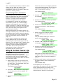
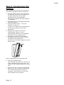
Security System Installation Guide © Cooper Security Ltd. 2009 Every effort has been made to ensure that the contents of this book are correct. However, neither the authors nor Cooper Security Limited accept any liability for loss or damage caused or alleged to be caused directly or indirectly by this book. The contents of this book are subject to change without notice. Printed and published in the U.K. This manual applies to the i-on40 control unit with version 2.00 software. For Your Safety This book contains several passages alerting you to potential problems or hazards. Each of these are marked by the words Note, Caution or WARNING.: Note: Describes conditions that may affect the proper functioning of the equipment (but will not damage the equipment). Caution: Describes actions that will physically damage the equipment and prevent its proper function. WARNING: Describes actions that are hazardous to health, or cause injury or death. Please pay particular attention to these marked passages. Other Publications for the i-on40: User Guide Instructions for setting and unsetting an alarm system based on the i-on40. Administrator’s Guide Detailed notes for the system administrator of an alarm system based on the i-on40. The following guides are available from the Cooper Security website: www.coopersecurity.co.uk Programming Reference Guide A detailed description of the Installer’s programming options available on the i-on40. Web Server Setup Guide Instructions on how to configure a Windows PC or laptop to use the i-on40’s built-in web server for installation programming. i-on Flashloader Installation and User Guide This booklet shows you how to install i-on Flashloader on your PC and use it to update the software on your i-on40 control unit. Page ii CONTENTS 1. Introduction..................................... 1 Communications............................... 1 Level Setting or Partitioned System..... 1 2. Before You Begin.............................. 2 Preparation ......................................... 2 Siting the Unit.................................. 2 Guided Tour ........................................ 2 Opening the End Station Case ............ 2 End Station PCB ............................... 3 Keypad Controls and Displays............. 3 Opening the Keypad ......................... 3 Power Availability................................. 4 3. Installation ...................................... 5 Step 1. Fit the Control Unit Box.............. 5 Caution: Static Electricity................... 5 Fitting............................................. 5 Step 2. Fit and Connect the Keypad(s) .... 5 Siting the Keypad(s) ......................... 5 Fitting............................................. 5 Connecting Keypads to End Station ..... 6 Keypad Addressing ........................... 7 Backlight Control .............................. 7 Tone Volume ................................... 7 Step 3. Connect End Station to Mains ..... 7 Mains Cabling .................................. 8 Mains Connection ............................. 8 Step 4. Connect Wired Zones................. 8 Four Wire Closed Circuit Connections... 8 Fully Supervised Loop Connections...... 8 Step 5. Connect Wired Peripherals.......... 9 Remote Loudspeaker (Optional).......... 9 Wired External Sounders (Optional) .... 9 Wired Outputs (Optional)................... 9 Step 6. Fit a Plug-By Communicator ..... 10 Step 7. Fit and Connect Battery ........... 10 Programming Before Installation....... 11 Step 8. Initial Power-Up...................... 11 Step 9. Commission the System........... 12 4. Programming ................................. 13 Entering the Installer Menu ................. 13 Leaving the Installer Menu .................. 13 Important! Saving Changes ................. 13 Restoring the Access Codes (1st stage Reset) .............................................. 13 Restoring Factory Defaults .................. 14 Installer Menu ................................... 15 Zone Types & Attributes ..................... 16 Output Types .................................... 18 Exit Modes ........................................ 21 7. Maintenance................................... 21 8. Technical Specification ................... 22 General ............................................ 22 Capacities ......................................... 22 Security............................................ 22 Radio ............................................... 22 Power Supply .................................... 22 Electromagnetic Compatibility.............. 23 Outputs ............................................ 23 Fuses ............................................... 23 Electrical Safety ................................. 23 Compliance Statements....................... 23 Compatible Equipment ........................ 24 Page iii i-on40 This page is intentionally blank. Page iv i-on40 1. Introduction The i-on40 is the control unit for a hybrid wired/wirefree alarm system intended for domestic and light commercial use. The control unit comprises an end station and up to four separate wired keypads. The end station has an ABS plastic case which contains the radio transceiver, power supply and backup battery. The keypad(s) connect to the end station by standard alarm cable. The keypads allow end users to set and unset the system, and the installer to configure the control unit. The keypads also contain integral proximity tag readers, allowing end users to control the system without having to remember access codes. A range of wireless peripherals is available for operation with the control unit. These include a door contact/universal transmitter, a passive infra red detector, smoke detector, external siren, 4 button remote control, and remote radio keypad. The control unit supports up to 16 wired alarm zones, 24 wirefree alarm zones, up to 16 hardwired outputs, 50 four-button remote controls, 50 two-button radio panic alarms, and 50 users. See page 22. Communications The i-on40 provides sockets for an add-on communication module. The available modules are: i-sd02 A speech dialler and public switched telephone network (PSTN) module that allows the control unit to send recorded speech messages and report alarm information using standard protocols such as Fast Format, SIA and Contact ID. This module also allows remote maintenance. i-dig02 A switched telephone network (PSTN) module that allows the control unit to report alarm information using standard protocols such as Fast Format, SIA and Contact ID. This module also allows remote maintenance. i-gsm02 A GSM module that allows alarm reporting, speech messaging and SMS text messaging over the mobile phone network. 8750 An Ethernet module that allows alarm reporting and remote maintenance over the internet. 8844 A GPRS module that allows internet protocol access over the mobile phone network. Level Setting or Partitioned System The i-on40 offers two basic ways of behaving as an alarm system: Part Setting. In a Part Setting system the i-on40 can set in one of four ways: either Full set or three varieties of Part Set. In Full set the control unit pays attention to all detectors. In each of the three Part Sets the control unit ignores detectors that do not have the appropriate Part Set attribute (see page 17 ). Partitioned System. In a Partitioned system the i-on40 provides the equivalent of four, smaller, independent alarm systems. Each system is a “Partition” of the i-on40. You can allocate any zone to each Partition. Each zone can also belong to more than one Partition. Each Partition can have a Full Set level and one Part Set Level. During installation the installer can allocate keypads, sounders or outputs to any of the partitions. This manual shows the simple procedure required to install the control unit and its keypad. When you have completed the physical installation please consult the Programming section for details of configuring the system to meet your exact requirements. For a detailed description of the Installer’s programming menu please read i-on40 Programming Reference Guide available from www.coopersecurity.co.uk. Page 1 i-on40 2. Before You Begin Preparation Before installation you should carry out a survey of the site. You need to know how many and what kind of detectors will be transmitting to the control unit. You also need to assess where the control unit must be placed in order to receive radio signals from the detectors successfully. Guided Tour Opening the End Station Case To gain access to the interior of the end station undo the two screws at the top of the case. Pull the top of the lid down, and then lift the lid out of the retaining lugs at the bottom of the case. 1 To do this you should conduct signal strength tests. Cooper Security produce the Scantronic 790r hand held signal strength meter for this purpose. Alternatively, you can power the control unit from a battery and use its built-in testing facility to measure the signal strength from a detector that you temporarily place at each planned location. Siting the Unit Do site the unit: Upright (battery at the bottom). Within a protected zone. As high as possible. However, do make sure that the unit is on a similar level to the other transmitters or receivers. 2 3 Figure 1 Opening the end station. WARNING: When connected to the mains with power applied mains voltages are present on the shrouded heads of the terminal screws of the mains connector (“8” in figure 1). 1 Do NOT site the unit: In the entry or exit zones, or outside the area covered by the alarm system. Close to or on large metal structures. Closer than one metre to mains wiring, metal water or gas pipes, or other metal surfaces. 2 2 3 3 4 5 Lower than two metres from the floor (ideally). Inside metal enclosures. Next to electronic equipment, particularly computers, photocopiers or other radio equipment, CAT 5 data lines or industrial mains equipment. Note: Some window glasses, especially those sold as “insulating” or “energy conserving” may be coated with thin metal or conducting films. These glasses are particularly poor at transmitting radio waves. If fitting two or more keypads make sure that you do not place the keypads within one metre to each other. (The proximity tag readers in each keypad will interfere with each other.) Remember not to place keypads on opposite sides of the same wall. Page 2 6 10 7 3 9 8 Figure 2 Control Unit 1. Central fixing keyhole. 2. Aerials. 3. Fixing holes. 4. Connector pins for Lid Tamper. i-on40 5. Printed circuit board (PCB). 6. Cable entry holes for detector and keypad wiring. 7. Transformer. 8. Mains connector block. 9. Cable entry hole for mains. 10. Back Tamper switch (if fitted). 10. Siren test output (not used in UK). End Station PCB 4 Keypad Controls and Displays 1 2 3 8 5 1 A 1 2 abc B 4 ghi 5 jkl 3 def 6 mno C 7 pqrs 8 tuv 9 wxyz D * 0 # 7 6 2 15 3 14 13 12 4 5 6 7 8 9 11 10 Figure 3 End Station Printed Circuit Board 1. Aerials (CAUTION: do not bend). 2. Tamper connector. 3. USB socket (Mini B). 4. Ethernet link activity LEDs. 5. 20VAC input (from transformer). 6. Battery connector. 7. Kick Start pins. 8. Ethernet socket. 9. “Heartbeat” LED 10. RS485 terminator. 11. Code reset pins. 12. Plug by connector pins 13-16. 13. Plug by connector pins 1 to 12. 14. Comms activity LED. 15. Sockets for plug on module. 1 2 3 Figure 5 Controls and Displays 1. LCD display (2 x 20 characters). 2. Programming keys. 3. Navigation keys 4. Alert LEDs 5. Setting and unsetting keys. 6. Panic Alarm (PA) keys. 7. Number/text keys. 8. Set/Unset LEDs. Opening the Keypad To open the keypad first gently prise off the trim on the front and remove the two screws. Next, carefully lever the front of the keypad (containing the pcb and display) away from the keypad rear housing. 1 2 4 4 3 10 9 8 7 6 5 Figure 4 End Station Main Connectors 1. Aux power. 2. Outputs (relay). 3. Aux power. 4. Keypad bus. 5. Wired zone connectors. 6. Ethernet connector. 7. Loudspeaker. 8. Wired siren tamper return. 9. Outputs (transistorised). Figure 6 Opening the Keypad Page 3 i-on40 3 Before connecting any external devices to the control unit, you must make sure that the control unit can provide sufficient current to power the system during a mains failure for the time required to meet Grade 2 PD6662 or EN50131-1. The amount of current available from the control unit depends on the battery fitted. The current taken by the control unit pcb and keypads is given in Technical Specifications on page 22. 1 2 3 4 Figure 7 Keypad Rear Housing 1. Central keyhole. 2. Rear tamper shroud. 3. Cable entry. 4. Fixing holes. Power Availability For example: in an alarm system with an ion40 control unit, two i-kp01 keypads, and 15 wired PIRs the system takes the following total current: 1 2 3 4 Device Current Control unit PCB 130mA 15 x PIRs at 20mA each 300mA 2 x i-kp01 at 30mA each 60mA (backlights off) Total 490mA A fully charged 7Ah battery can provide 580mA for 12 hours. In this example a 7Ah battery should exceed the Grade 2 requirements. 5 6 ET B A 12V 0V 4a 4b 4 3 2 ABCD-ON ON BACKLIGHT BRIGHT Figure 8 Keypad PCB 1. Sounder. 2. Sounder volume control. 3. Tamper switch. 4. Jumpers for addressing and LED function: 4a Addressing 4b LED functions 5. RS485 termination jumper 6. Connector for control unit (note that the ET terminals are inactive). Page 4 i-on40 the back of the end station on a wall. Use No10/M5 countersunk screws at least 36mm long. Figure 9 shows the fixing holes and cable entries. 3. Installation Exposure to Radio Frequency Radiation The radiated output power of this device is below those levels considered safe by European exposure limits. Nevertheless, when fitting the product place it in such a manner as to minimise the potential for human contact during normal operation. To minimise exposure, users should be more than 200 mm from the device during normal operation Step 1. Fit the Control Unit Box Step 2. Fit and Connect the Keypad(s) Siting the Keypad(s) Do site the keypad(s): Within the area protected by the alarm system. At a convenient height and location for the user. Caution: Static Electricity Like many other electronic products, the control unit contains components that are sensitive to static electricity. Try not handle the PCB directly. If you must handle the PCB, take the standard precautions against damage by static electricity. Out of sight of potential intruders. Do NOT site the keypad(s): Next to electronic equipment, particularly computers, photocopiers or other radio equipment, CAT 5 data lines or industrial mains equipment. Where the cable run from the end station will be longer than 100m (see Cable Configuration and Length). Fitting 1 1 Protect the unit from dust and drilling debris when drilling the fixing holes. Note: Do not site two or more keypads closer than one metre together, otherwise their prox readers will interfere and be unable to read tags. 1 Fitting Use M4 25mm countersunk screws in at least three fixing holes when mounting the back of the keypad on the wall. 2 1 2 Figure 9 Fixing Holes and Cable Entries 1. Fixing holes. 2. Cable entries. Figure 10 Screw Keypad Back Box to Wall Cooper Security recommend that you use at least four fixing holes when mounting Page 5 i-on40 Star Connecting Keypads to End Station Daisy Chain Cable Type In general, the control unit requires standard 7/0.2 un-screened four core alarm cable for wiring to keypads. For maximum performance in harsh environments use twisted pair cable with a characteristic impedance of 100-120ohms eg: CAT5 or cable designed for RS485. terminate MENU A B MENU 1 2 abc B 4 ghi 5 jkl 7 pqrs 8 tuv 9 wxyz * 0 # A B 1 2 abc 3 def 4 ghi 5 jkl 6 mno 7 pqrs 8 tuv 9 wxyz * 0 # 100m A B MENU 2 abc 3 def A 2 abc 3 def 4 ghi 5 jkl 6 mno B 4 ghi 5 jkl 6 mno 7 pqrs 8 tuv 9 wxyz 7 pqrs 8 tuv 9 wxyz * 0 # * 0 # 1 1 2. The continuity of the cable screen is most important and screens MUST be continuous along the full length of the cable. 6 mno 9 wxyz 0 # 1 2 abc 3 def 4 ghi 5 jkl 6 mno 7 pqrs 8 tuv 9 wxyz * 0 # 250m MENU A B 1. Avoid earth loops by connecting the screen on the cable to mains earth at the end station but not at the keypad. 3 def 5 jkl 8 tuv MENU A B Screened cable may prove necessary if the installation site has equipment that produces high levels of R.F. (Radio Frequencies), for example welding equipment. If screened cable is required, you should keep to the following guidelines: 2 abc 4 ghi 7 pqrs * 3 def 6 mno MENU Use one pair for data bus A & B. Use the other pair for 12V & 0V. 1 MENU A terminate 1 2 abc 3 def 4 ghi 5 jkl 6 mno 7 pqrs 8 tuv 9 wxyz * 0 # MENU A B 1 2 abc 3 def 4 ghi 5 jkl 6 mno 7 pqrs 8 tuv 9 wxyz * 0 # Figure 11 Keypad Wiring Configurations For star configurations the cable length from control unit to the most distant keypad should not exceed 100m. For a daisy chain configuration the total cable length should not exceed 1,000m, Connection Figure 12 shows the wiring connections at the keypad and control unit. 3. If the cable enters any metal enclosure, ensure the screen is isolated from the case. Cable Segregation Segregate the keypad cabling from any other wiring, such as mains supply cables, telephone cables, computer network cables and R.F. cables. Use cable ties to keep cables separated. Keep the keypad cable clear of cables supplying sounders or extension loudspeakers. ET B A 12V 0V Cable Configuration and Length You can connect up to four wired keypads to the end station. You may connect the keypads either in daisy chain (serially), or in star (parallel) configuration at the end station connector. Figure 12 Keypad Connection Temination The i-on40 data bus uses the RS485 interface. Because of this the ends of the line in some configurations may be terminated to improve performance in electrically noisy environments or where there are long cable runs. Both control panel and keypads have a termination link on their PCBs (see 10 in Fig 3 for the Page 6 i-on40 control unit and 5 in Fig 8 for the keypad). Fitting a jumper to the pins adds a termination to the cable. In a daisy chain configuration terminate each end of the chain (see Fig 11 ). In a star configuration: If there are only two keypads then this is the same as a daisy chain configuration. If required terminate at each keypad. ABCD-ON MENU A 1 2 abc 3 def B 4 ghi 5 jkl 6 mno 7 pqrs 8 tuv 9 wxyz * 0 # The set/unset LEDs shows the setting status of the system. (Full set is left hand led.) BL ON BRIGHT MENU A 1 2 abc B 4 ghi 5 jkl 6 mno 7 pqrs 8 tuv 9 wxyz * 0 # 3 def If there are more than two keypads AND two cables are long while the remaining keypad cables are short (less than 10m) then it is possible to terminate at the two keypads with long cables. The key backlights are disabled. They will glow briefly for five seconds when a user presses a key. If there are more than two keypads BUT each keypad cable is more than 10m then DO NOT terminate. BL Keypad Addressing Each keypad connected to an end station must have a unique address. See Figure 8 on page 4 for the position of the addressing jumpers. ON BRIGHT MENU MENU A 1 2 abc 3 def A 1 2 abc 3 def B 4 ghi 5 jkl 6 mno B 4 ghi 5 jkl 6 mno 7 pqrs 8 tuv 9 wxyz 7 pqrs 8 tuv 9 wxyz * 0 # * 0 # The key backlights glow all the time at normal intensity. MENU MENU BL ON BRIGHT A B 1 2 abc A 1 2 abc 3 def B 4 ghi 5 jkl 6 mno 7 pqrs 8 tuv 9 wxyz * 0 # 3 def 4 ghi 5 jkl 6 mno 7 pqrs 8 tuv 9 wxyz * 0 # MENU MENU A 1 2 abc 3 def B 4 ghi 5 jkl 6 mno 7 pqrs 8 tuv 9 wxyz * 0 # 4 3 2 2 A 1 2 abc B 4 ghi 5 jkl 6 mno 7 pqrs 8 tuv 9 wxyz * 0 3 def # 4 3 2 The keypad backlights glow all the time, extra bright. 1 MENU Tone Volume To alter the volume of non-alarm tones from the keypad adjust the keypad sounder volume control (2 in Fig 8): MENU A 1 2 abc 3 def A 1 2 abc B 4 ghi 5 jkl 6 mno B 4 ghi 5 jkl 6 mno 7 pqrs 8 tuv 9 wxyz 7 pqrs 8 tuv 9 wxyz * 0 # * 0 # 4 3 2 3 4 3 2 3 def Louder 4 Figure 13 Keypad Addressing Jumpers Backlight Control Note: This control changes the volume of non-alarm tones (for example Exit/Entry tone). The volume of alarm tones is fixed. Softer You can control the appearance of the keypad backlights and set/unset LEDs by fitting links over the appropriate jumpers on the keypad pcb (see Figure 8 on page 4 for the position of the jumpers). The jumpers have the following functions: ABCD-ON MENU A 1 2 abc B 4 ghi 5 jkl 6 mno 7 pqrs 8 tuv 9 wxyz * 0 # 3 def Step 3. Connect End Station to Mains WARNING: ENSURE THAT THE MAIN SUPPLY IS DISCONNECTED AND ISOLATED BEFORE MAKING ANY MAINS CONNECTIONS. All mains electrical connections must be carried out by a qualified electrician and must comply with the current local regulations (e.g. IEE). The set/unset LEDs are disabled. Page 7 i-on40 Mains Cabling Make sure that the mains supply cable does not run vertically behind the aerials within the end station case. If you wish run mains cable through the side of the case, make sure that they are horizontal for the last metre before entering the case. >1m Step 4. Connect Wired Zones Four Wire Closed Circuit Connections >1m Tamper Zone 2 Tamper Zone 1 Alarm Zone 2 Alarm Zone 1 Figure 14 Mains Cabling Clearance Note: To avoid mains interference, the mains cable must enter the control unit through its own cable entry hole ( 9 in Fig 2) and must not be mixed with other cables. Mains Connection Figure 15 shows the mains connection. Connect to a suitable supply using a double pole disconnect device in accordance with EN60950-1. Caution: Do not apply power at this point. Anchor the mains cable with a strain-relief tie. There is a eye located near the mains cable entry hole for this purpose. N L 230V ~50Hz 200mA T250mA 250V Figure 15 Mains Connection Page 8 Figure 16 Closed Circuit Loop Zone Wiring Fully Supervised Loop Connections Figure 17 shows the wiring connections for Fully Supervised Loop zones. Note that the resistance values shown are examples. The allowed values for Alarm Contact/End of Line are: 4k7/2k2. 1k0/1k0, 2k2/2k2, or 4k7/4k7. Use the same pair of values for ALL FSL wired zone circuits. When programming select the correspondings value in Installer Menu - System Options - Wired Zone Type If you wish to connect two or more detectors to a FSL zone, the diagram at the bottom of Figure 17 shows the connections required. Figure 18 shows an example of wiring double doors with two door contacts to one FSL zone. Each door contact is a reed switch, connected between the outer terminals. The inner (shaded) terminal is not connected, and provides a spare terminal. i-on40 Step 5. Connect Wired Peripherals 100 Ohms 12V + 0V Tamper In 4K7 Alarm contacts Zone 2 Tamper Out Strobe +ve Strobe -ve Trigger -ve 2K2 EOL Tamper contacts Zone 1 4K7 Alarm contacts 2K2 EOL Tamper contacts 4K7 Zone 1 Alarm contacts Alarm contacts Tamper contacts Tamper contacts 2K2 EOL +LS -LS Max 10 devices per circuit (not recommended) Figure 19 Connecting Wired Peripherals Figure 17 Fully Supervised Loop Zone Wiring Spare Blue To zone • contacts Yellow 2K2 EOL Red 4K7 Black Figure 18 Example: Wiring Two Door Contacts to One FSL Zone. The end station pcb provides four connectors for wired outputs. Outputs 1 and 2 are voltage free relay outputs. Outputs 3 and 4 are driven by transistors, and are capable of sinking a maximum 500mA when active. By default outputs 3 and 4 are 0V when active, +12V when inactive. If you wish to reverse the polarity of these two outputs use Installer Menu Outputs - Wired Outputs – Output 3(4) - Polarity. Remote Loudspeaker (Optional) If you wish to add a wired Loudspeaker unit, then connect it as shown in Figure 19. Wired External Sounders (Optional) Wired external sounders differ in their methods of connection. Figure 19 shows an example of a general method of using the outputs to connect a wired sounder. Note: If you do not wish to connect a wired external sounder then make sure you link TR to 0V. This prevents the control unit reporting Bell Tamper unnecessarily. Wired Outputs (Optional) Figure 19 shows an example of using the wired outputs to drive an indicator LED. Page 9 i-on40 Step 6. Fit a Plug-By Communicator If the system has already been installed: The control unit can be connected to a separate communicator or speech dialler (for example, the Scantronic 8400, 8440, 660 or RedCare STU). Figure 20 shows the connections provided by the communications wiring harness. 6. Apply mains power. Com Connector Cable, Part number 485210 4. Re-connect the battery. 5. Fit the case lid. 7. Test communicator operation. Line Monitoring for a Dual-Path Communicator If a standalone dual-path (landline and mobile) communication device, such as a RedCARE STU, is connected to the plug-by connector, you need to do the following to obtain correct line fault reporting (this is not necessary if you are using a plug-on module): 1. Wire a panel output programmed as type "ATS Test" to the ATS Test input of the communicator. Com Connector Cable, Part number 11960058 O/P10 (Brown) O/P11 (Orange) O/P12 (Yellow) O/P13 (Green) Figure 20 Plug-By Communicator Wiring Note: Comms O/P4 will be active when the system is unset. This is normal. To fit a communicator, follow the instructions below. Caution: Follow the instructions in the order shown, or you may damage the control unit and/or communicator. 1. Disconnect mains and battery power from the control unit and remove the case lid, if the system has already been installed. 2. Wire the Line Fault output of the communicator to the Line Fault input of the plug-by connector. The communicator must provide +12Vdc to indicate a line fault (for example, if the Line Fault output at the communicator uses a relay, connect the common terminal of the relay to +12Vdc and the normally-open terminal to the Line Fault input of the plug-by connector). The panel will generate an "ATE L.F. Single" alert if only one of the networks is not available, or "ATE L.F. All" if both networks are not available. Step 7. Fit and Connect Battery Fit a 7Ah Lead Acid battery into the battery compartment in the bottom of the control unit, see Figure 21. Make sure that you secure the battery to the case with the strap provided. Connect the battery leads, red to the positive, black to the negative terminals of the battery. 2. Make any necessary connections from the communicator to the communication wiring harness. The default is a 12V positive voltage when the output is inactive. Refer to the next section if you are using a dual-path communicator. 3. Plug the Communication Wiring Harness onto the communications connector on the main PCB. Page 10 Figure 21 Fitting the Battery i-on40 Note: Connecting the battery without mains power will not start the system. (See “Programming A Control Unit Before Installation” below if you wish to start the system on battery power.) From this point on, the display operates in the selected language. If you want to change the language later use Installer Menu - System Options - Language. The display shows: COUNTRY DEFAULTS *UK Programming Before Installation If you prefer, you can make the control unit learn the detectors and other peripherals before installing the system in its final location. You will need to temporarily connect a keypad to the end station. It is possible to operate the end station from battery power (or a 12Vdc supply) without connecting the unit to a mains supply. However, in order to start the end station processor running you must briefly short the Kick Start pins together after connecting the battery. When programming the system while it is running on battery only, remember to leave the Installer Menu before removing power. If you do not do so all your changes will be lost, see Important! Saving Changes on page 13 If you wish to program the control unit from a laptop or PC you can do this by connecting the control unit to your PC via Ethernet. You will need a CAT 5 patch cable and a laptop or PC with a standard web browser. See the separate publication ion40 Web Server Set Up Guide for instructions on how to set up your PC/laptop and the control unit. Step 8. Initial Power-Up WARNING: During initial power-up all the keypad sounders and any internal loudspeaker will give an alarm tone. If you are working at the top of a ladder make sure that the sudden noise does not startle you and cause a fall. 1. Apply mains power to the control unit. The keypads and internal sounder give an alarm tone. The heartbeat LED (see fig 3 ) starts flashing. The display initially shows: Language? English 2. Press u or n to show other languages on the bottom line of the display. for example: 4. Press u or n to show other countries, for example: COUNTRY DEFAULTS Italy 5. Press Y to select the country you want. The display shows: A : Partition mode B : Part set mode 6. Press A or B to select either a partitioned system or a Part Setting system. The display shows: Load Profile? 7. Either: Press Y to load the Profile. Or: Press system X to start with a blank The end station loads your choice of profile, and then shows: WIRED ZONE TYPE *2-wire FSL 2k2/4k7 8. Press u or n to show the range of wiring types available, for example: WIRED ZONE TYPE 4-wire CC 9. Press Y to select the wiring type you intend to use for the wired zones The display shows: I-ON40 00:00 01/01/2009 Note that the alert LEDs round the navigation glow red. This is because the end station lid is off and the tamper is active. 10. Remove both battery and mains power. Re-apply battery power followed by mains. The sounders stop. At this point you can carry on to commission the system. See the next page. Note: Setting the time and date is an administrative user function. See i-on40 Administrator’s Guide for instructions. Language? Nederlands 3. Press Y to select the language you want. Page 11 i-on40 Step 9. Commission the System After installing the control unit you should commission the alarm system as follows: 1. Use the Installer Menu (see Chapter 4) to teach the control unit the identity of its radio detectors and any other peripherals. See the installation instructions supplied with each detector or peripheral. 2. Install detectors and peripherals at their selected locations. 3. Use the Installer Menu – Test (see Chapter 5) option to: a) carry out a walk test of the detectors. b) test the operation of any other peripherals. 4. Program the system to suit user requirements. See the i-on40 Programming Reference for a detailed description of the Installer Menu. 5. Assemble and close the end station: a) Hook the lid of the control unit into the bottom of the back box. b) Close the lid and then tighten the two fixing screws. 3 2 1 Figure 22 Replacing the end station lid. 6. Leave the Installer Menu. The red LEDs should go out, and the rim of the navigation keys glow green. The system is now ready to hand over to the user. 7. Instruct the user on how to operate the system. See the i-on40 User Guide and the i-on40 Administrator’s Guide. If necessary, show them how to set the time and date on the system. Page 12 i-on40 4. Programming This section is summary of the Installer Menu on the i-on40. Please see the i-on40 Programming Reference for a more detailed description. Entering the Installer Menu Leaving the Installer Menu If you wish to leave the Installer Menu at any time. X 1. Press until the display shows the words “Leave installer mode?”. Leave installer mode? Y 1. Make sure the system is unset and showing the standby screen (time and date). 2. Press to leave Installer menu. (Press X if you do not want to leave the menu.) 2. Key in the Installer access code. When delivered from the factory the default Installer access code is “7890”. The default user code is “1234”. The display shows the time and date. As you start to key in the code the display shows: Enter Access Code: (* ) When you key in the last digit of the Installer access code the display shows: User Code Required ( ) Note: You will see this screen the first time you enter the Installer menu on a new control unit, or if you have restored Factory Defaults. 3. Key in the default user code (see Note below). The display shows: Installer Menu Detectors/Devices> 4. Press u or n to display more items from the menu. Each item appears on the bottom line of the display in turn, for example: Installer Menu Outputs > 5. Press > to select that item of the menu. The option you selected now appears on the top line. If there are any suboptions for that selection, then the first of them appears on the bottom line, for example: Outputs Edit Outputs You can press u or n to display the other sub-options. > Note: If you key in an access code incorrectly, the display shows four “stars”. Key in the code again. If you key in a total of ten incorrect codes then the system locks you out for 90 seconds. i-on40 12:00 02/01/2008 The system is ready for use. Note: If you attempt to leave the Installer Menu when a detector tamper is active then the keypad displays a fault message telling you which detector is causing the problem. X Press to return to the Installer Menu. You must either close the detector tamper or delete it from the system before you can leave the Installer Menu. Important! Saving Changes When you make changes to the Installer Menu the control unit holds those changes in temporary memory until you leave the Installer Menu. As you leave the Installer Menu the control unit writes those changes into a permanent store. If you remove all power BEFORE you leave the Installer Menu then the control unit will lose your changes. Note that this does not apply if you restore Factory Defaults, that change takes place immediately. Restoring the Access Codes (1st stage Reset) If the user and/or Installer codes are lost then: 1. If possible, enter the Installer menu. Note: If you cannot enter Installer Menu then the end station will start a tamper alarm when you open the end station lid. 2. Remove mains power, then open the case and disconnect the battery. Note: This procedure will not work if the control unit lid tamper remains closed. Page 13 i-on40 3. Identify the Reset Codes pins on the main PCB (see Figure 3). 4. Short the Reset Codes pins together using a screwdriver or jumper link. (Keep the short on until step 6.) 5. Apply mains power. The control unit loads the factory default access codes: User 1: 1234, Installer: 7890. After a short pause the keypad display shows the time and date. The red LEDs glow to show an alert that the panel lid is open. The system may start a tamper alarm. 6. Remove the short from the Reset Codes pins. 7. Reconnect the battery. 8. Close the end station lid (to restore the tamper switch). 9. Key in 1234 to silence the sirens (if necessary). Press Y twice (if necessary) to acknowledge any alerts. If the red LEDs around the navigation key still glow then there may be an alert for a missing battery that needs acknowledgement. To force the end station to check the battery: 10. Enter Installer Menu and then leave it again. 11. Press Y, key in 1234, press Y again. The navigation key LEDs should now glow green. Restoring Factory Defaults If you wish to restore all factory default options then: 1. From the Installer Menu select System Options – Restore Defaults – Factory Defaults. The display asks for confirmation. 2. Press Y to load defaults. (Press X to go back to the Installer Menu without changing defaults.) The display asks you to select Partition Mode or Part Set Mode. 3. Press A or B to select the desired mode. The display asks you to select the zone wiring type. Page 14 4. Press u or n to display the desired wiring type on the bottom line of the display and then press Y to select it. The system loads all defaults except for Access Codes and the Log (see Note). The display returns to the Installer Menu. Note: The log is protected and cannot be erased by the Installer. i-on40 Installer Menu 4 SYSTEM OPTIONS 3 SETTING OPTIONS2 Full Set Wired Zone type Name User Access Exit Mode PA keys active Part Set B Quick Set Name Quick Omit Exit Mode User code reqd Part Set Alarm Response User reset Part Set Final Exit Zone alarms7 Zone tampers Part Set Entry Route System tampers Part C, D (See Part Set B) DD243 Exit time Confirmation Entry time Confirmation time Strobe on Set After Entry Strobe on Unset Entry Keypad Lock 3 PARTITIONS1 Sounder on Partition 1...4 Siren on Name Unconfirmed reset Exit Mode Confirmed reset Exit Time Global Confirm Entry Time Profiles Alarm Response Language Part Set Exit Mode Restore Defaults Part Set Alarm Response Installer Code Part Set Final Exit Installer Text Part Set Entry Route Remote Needs Entry Strobe on Set PA Response Strobe on Unset Auto Rearm7 Siren Delay Communications 5 COMMUNICATIONS 6 TEST Siren Time (cont’d) ARC Reporting5 Sirens & Sounders Loudspeaker Volume Call Mode Wired Keypad 5 Entry Alarm Delay SMS Phone book Walk Test Supervision Call Mode IP Network5 Zone Resistances Jamming Messages Account Number Signal Strengths Force Set Phone Book Report Type Detectors Tamper Omit Triggers Fast Format channels3 Radio Keypads CSID Code Line Fail Response CID/SIA Events4 External Sirens Silence Alerts IP Network (Own) Restorals4 WAMs Web Server 7 VIEW LOG Burg Comms Rearm3 Remotes8 5 GPRS 21CN FF Ack time3 Panic Alarms8 Ethernet5 Send tamper as burg4 Outputs 8 ABOUT Downloading Dynamic Test Call Radio Outputs Panel Account Static Test Call Wired Outputs Comms Connection Type Speech Dialler Plug-by outputs 5 Panel Ethernet Rings to Answer Call Mode Remotes 5 Answer on one ring Messages Panic Alarms 5 Access Mode Phone Book Prox Tags Phone Book5 Triggers ARC Reporting 5 Secure Callback Destinations Speech Dialler5 5 Modem Baud Rate PSU Current Call Acknowledge 1 Appears only in a Partitioned system (or when zones have a type other than “Not Used”. 2 Appears only in a Level Setting system. 3 Appears only when Report Type=Fast Format 4 Appears when Report Type=CID or SIA 5 Options visible depend on communications module fitted. 6 Appears when zone is given a type other than “Not Used”. 7 Appears only when System Options – DD243 – Confirmation is “off”. 8 Appears only when device learned in. 1 DETECTORS/DEVICES Detectors Add/Del Detectors Zone 17...40 Delete all Edit Zones Zone 01...40 Name Type Partitions1 Attributes6 Wired Keypads Keypad 01...04 Name Partitions1 Key A...B1 Radio Keypads Add/Del Radio Keypad Edit Keypads External Sirens Add/Delete Ext. Siren Edit external siren Info Modules Teach Info Module Updates Ready-to-set LED WAMs Add/Del WAM View WAM 2 OUTPUTS Radio outputs Add Outputs Edit Outputs Output 01...08 Name Type Wired outputs Output 1...4 Name Type Polarity Partitions* Plug-by outputs Output 1...12 Name Type Polarity Partitions* Page 15 i-on40 Zone Types & Attributes (Hint: You can select a zone type quickly by keying the number shown in brackets after the type’s name, for example:“05” to select Alarm Abort, “02” to select Panic Alarm, “11” to select External PSU A/C Fail. The number does not appear on the keypad display.) Not Used (00) The alarm system will not respond when an event triggers this detector. Panic Alarm (01). Operating a device programmed as ‘Panic Alarm’ (PA) will start an audible alarm. If a communications module is fitted there may also be an alarm transmission to the Alarm Receiving Centre (ARC), depending on how you have programmed the ARC Reporting option. PA alarms operate whether the system is set or unset. Fire Alarm (02). Smoke or heat detectors connected to Fire Alarm zones cause the sirens to give a pulsing fire signal. Fire alarms operate whether the system is set or unset, and will always trigger communications, if a communications module is fitted and enabled. Normal Alarm (03). A zone programmed as ‘Normal Alarm’ will start an alarm when the system is set. (See “Zone Attributes” on page 17.) 24 Hour Alarm (04). Activating this zone causes an alarm whether the system is set or unset. Final Exit (05). Zones of this type must be the last detector to be activated on exit, or the first to be activated on entry. You can use zones of this type to finally set the system, or to start the entry procedure. Note: If you give a Final Exit zone any of the Part Set attributes then you can program that zone to behave like a Normal Alarm zone if the user part sets the system. Entry Route (06). Use this zone type for detectors sited between the Final Exit door/detector and the keypad. If an ‘Entry Route’ zone is triggered when the system is set, an alarm will occur. If the entry/exit timer is running when an Entry Route zone is triggered then no Page 16 alarm occurs until the entry/exit timer expires. Note: If you give an Entry Route zone one of the Part Set attributes then you can program that zone to behave like a Final Exit zone if the user part sets the system. Technical Alarm (07). Use this zone type when you want to monitor equipment, for example a freezer, without raising a full alarm. If a technical alarm zone is activated (and the control unit correctly programmed) then the control unit starts communication and logs the event. If the technical alarm occurs while the system is set, then system makes no audible alarm. When a user unsets the system the keypad shows an alert. If a technical alarm zone is activated while the system is unset then the system starts an alert immediately and gives a brief tone from the keypad every few seconds. When a user enters a valid access code the keypad stops the tone and displays the zone causing the alarm. When the user acknowledges the alert by pressing Y the control unit resets the technical alarm ready for the next event. Key Switch Momentary (08). Use this zone type to connect a momentary keyswitch to a single zone. In a Part Setting system the keyswitch can Full Set or unset. In a Partitioned system you can allocate the keyswitch to one or more partitions. Each time a user operates the keyswitch the control unit changes the current set state. Key Switch Latched (09). Use this zone type to connect a fixed position keyswitch to a single zone. In a Part Setting system the keyswitch can Full Set or unset. As with Momentary keyswitches, you can allocate the zone to one or more Partitions (see above). When the user closes the keyswitch contacts the control unit sets the allocated Partition. When the user opens the contacts the control unit unsets the allocated Partition. i-on40 Notes: 1. The keyswitch zone types are intended for use on zones that connect to an access control keypad, electronic key or other type of hardwired device used to set or unset the system. 2. When the user operates the keyswitch while the system is unset then the control unit starts the programmed exit mode. 3. When the user operates the keyswitch while the system is set then the control unit unsets the system immediately. 4. The user cannot reset the system from a Keyswitch zone. 5. Do not assign more than one Latched Key Switch zone to a partition. Tamper (10) Use this zone type to monitor the tamper status of external equipment. The control unit monitors a Tamper zone at all times. When triggered in the unset condition, only internal sounders operate. When triggered in the set condition, the alarm response determines whether external sounders, strobe and communications also respond to the alarm. External PSU A/C Fail (11) Use this zone type to monitor the A/C Fail output of an external power supply unit. If a power supply unit triggers a zone with this type then the control unit waits for a random time between 52 and 59 minutes before activating any output programmed as “AC Fail” and causes an alert that displays “External mains fail” on the keypad. If the alarm system is set then the control unit logs the event, starts any programmed communication, but does not start an alarm. External PSU Battery Fault (12) Use this zone type to monitor the Battery Fault output of an external power supply unit. If an external PSU triggers a zone with this type then the control unit activates any output programmed as “Battery Fault” and causes an alert that displays “External Battery Fault” on the keypad. If the alarm system is set then the control unit logs the event, starts any programmed communication, but does not start an alarm. External PSU Low Volts (13). Use this zone type to monitor the Low Battery output of an external power supply unit. If a power supply triggers a zone with this type then the control unit activates any output programmed as “Low Battery” and causes an alert that displays “External Low Battery” on the keypad. If the alarm system is set then the control unit logs the event, starts any programmed communication, but does not start an alarm. External PSU Fault (14). Use this zone type to monitor the fault output of an external PSU. If a power supply triggers a zone with this type then the control unit activates any output programmed as “External PSU Fault” and causes an alert that displays “External power fault” on the keypad. If the alarm system is set then the control unit logs the event, starts any programmed communication, but does not start an alarm. Zone Attributes Note: a)This menu does not appear if a zone has the type “Not Used”. b) Some attributes are not available for certain zone types. The display shows the available attributes for the zone type you select. Chime When enabled by the user, the system gives a non-alarm warning tone when any zones programmed as ‘Chime’ are opened. This facility operates only while the system is unset. Soak Test Use this zone attribute if you want to place under long term test a detector that you suspect is giving false alarms. Zones with this attribute are disabled for 14 days after you return the control unit to user/unset mode. If the zone remains inactive for the whole fourteen days then after midnight on the 14th day the control unit returns the zone to normal use. If the zone is activated during those 14 days while the system is set then the control unit logs the event as a “Soak Test Fail Zn” (n is the zone number) without sounding any sirens or starting communications. The Page 17 i-on40 control unit also lights the red LEDs around the navigation key on the keypad to alert the user. You can apply the soak test attribute to Normal Alarm, Entry Route and Tamper zone types. Double Knock Zones programmed with this attribute will cause an alarm only if the zone is EITHER triggered, restored and triggered again within a five minute period, OR if the zone remains active for 10 seconds. You can apply the Double Knock attribute to the Normal Alarm and Entry Route zone types. Part Set B (Not visible in a partitioned system.) When a user presses button B (part set), the control unit sets only those zones where the Part Set B attribute = “Yes”. Part Set C (Not visible in a partitioned system.) When a user presses button C the control unit sets only those zones where Part Set C attribute = “Yes”. Part Set D (Not visible in a partitioned system.) When a user presses button D the control unit sets only those zones where Part Set D attribute = “Yes”. Part Set (Not visible in a Part Setting system.) When a partition is Part Set, zones in that partition with this attribute are set. Note that if a zone is in more than one partition, all partitions have to be set or part set before this zone will be set. Omittable This attribute applies to Normal Alarm, 24hr and Technical zone types only. A) When a zone has this attribute, a user can omit it before setting the system. B) If a user tries to set the system when a zone with this attribute is open (active) the control unit alerts them and pauses the setting procedure. The user can acknowledge the alert by pressing Y and continue setting. You must enable this feature in the System Options – User Access – Quick Omit menu. Page 18 Force Set Omit When this attribute is set to Yes a user with a remote control can set the system while the zone is open (active). (You must enable this feature in the System Options – Force Set menu. Output Types You can select an output type quickly by keying the number shown in brackets after the type’s name, for example:“04” to select Open/Close, “02” to select Panic Alarm, “19” to select General Fault. (The number does not appear on the keypad display.) With Normal polarity a transistorised output applies 0V when active and +12V when inactive. With Inverted polarity the output applies +12V when active. Type: Active when: Not Used (00) (Never) Fire Alarm (01) The control unit starts a fire alarm. Panic Alarm (02) The control unit starts a panic alarm. Burglar Alarm (03) Any of the following zones are triggered: Normal Alarm Tamper (in a set system) Entry Route Tamper Zone (in a set system) Entry time expires 24 hour (in a set system) Open/Close (04) The system is unset. Inactive when the system is set. Alarm Abort (05) An alarm in the selected partition has been aborted by the user within the 90s abort period. Deactivates when the alarm is reset. Technical Alarm (06) There is a technical alarm. Confirmed Alarm (07) There is a confirmed alarm. Deactivates when the system is reset. RF Low Battery (08) A wirefree detector reports a low battery. The output remains active until all detectors stop reporting low batteries. i-on40 Type: Active when: RF Supervision (09) There is a supervision failure on any radio zone. The output remains active until all supervision failures are reset. RF Jamming (10) The control unit detects jamming. The output remains on until all jamming disappears. Tamper (16) The control unit detects tamper on any device; deactivates when tamper is reset. RF Fault (11) There are any of the following faults: RF Low Battery, RF supervision, RF jamming. Zone Omit (Setting) (17) Panel A/C Fail (12) Either Mains power is absent for between 52 and 59 minutes, OR a zone of type “External PSU A/C Fail” has been triggered. The control unit deactivates the output if a user keys in a valid access code after mains power has been restored. The user Omits a zone while setting the system. The output deactivates when the control unit restores the zone. Zone Omit (System) (18) Panel Battery Fault (13) The control unit detects a fault with its backup battery, OR a zone of type “External PSU Battery Fault” has been triggered. If the alert was caused by an “External PSU Battery Fault” zone then the control unit deactivates the output when the zone has been restored and a user has acknowledges the fault by entering a valid access code. (Operates only when DD243 is enabled.) In the event of an unconfirmed alarm, the system will rearm itself when the confirmation timer expires. If the zone that caused the unconfirmed alarm is still active at the time of the rearm, the control unit will omit that zone and activate the output. The control unit will restore the zone and output when a user or engineer resets the system. General Fault (19) There is any event that causes an alert indication on the keypad. ATS Test (20) (This output type appears only for Plug-by outputs.) The line fault input signal goes to 12V. The operation of the Line Fault input and the ATS test output must comply with the requirements of BSIA form 175. Siren (21) The control unit starts a full alarm, a panic alarm or a fire alarm (the siren has a distinctive tone during a fire alarm). The control unit deactivates this output at the end of the siren time. Strobe (22) The control unit starts a Full alarm, panic alarm or fire alarm. The output remains active until the user disarms the system. Entry Exit Follow (23) The entry or exit time starts and deactivates at the end of the entry/exit time, or if the entry/exit time is terminated. The output can be used for a separate entry/exit buzzer. Note that the output does not If the alert was caused by a fault with the control unit’s backup battery then the control unit deactivates the output when it detects a good battery and a user acknowledges the alert. Type: Note: To cause the control unit to check its backup battery enter and leave the Installer Menu. External PSU Low Volts (14) An external power supply has triggered an External PSU Low Volts zone. The control unit deactivates the output when the zone has been restored and a user has acknowledges the fault by entering a valid access code. External PSU Fault (15) An external power supply fault signal triggers a Power output fault zone. The control unit deactivates Active when: the output when the zone has been restored and a user has acknowledges the fault by entering a valid access code. Page 19 i-on40 Type: Active when: Type: Active when: operate if the exit mode is silent set or instant set. Part Set B (35) Setting Part Set B. Deactivated on unsetting Part Set B. (Available only in a Part Setting system) Part Set C (36) Setting Part Set C. Deactivated on unsetting Part Set C. (Available only in a Part Setting system) Part Set D (37) Setting Part Set D. Deactivated on unsetting Part Set D. (Available only in a Part Setting system) Set Fail (38) A set command fails. Remains active until the user acknowledges the set fail. Armed (24) The system is full or part set. PIR Set Latch (25) The system is set. Inactive when the system is unset or an alarm condition occurs. The output is active for one second when a reset is performed or when the control unit leaves installer mode. Shock Sensor Reset (26) Exit time starts. The output remains active for five seconds. Use this output to reset shock sensors (for example, the "Viper"). Walk Test (27) A user starts Installer- or User Walk Tests. Also active during the time between silencing and resetting the system. This output can be used on movement detectors that are able to switch off the Walk Test lamp in any state other than a Walk Test. Zone Follow (39) A specified zone has been triggered. If you select this type for a zone then the display shows an extra “Follow” option for the output. Use this option to select the zone you wish the output to follow. (You can follow a “not used” zone.) Smoke Sensor Reset (28) This output is active (0V) all the time except when a user acknowledges a fire alarm: after which the control unit deactivates the output for three seconds. This output type is designed to be connected to low-voltage smoke detector reset terminals. Zone Alarm (40) The selected zone causes an alarm. Deactivated when the alarm has been reset. When programming this output type the installer can select a specific zone for the output to follow. (You can follow a “not used” zone.) User Defined (41) The user switches the output on or off from the keypad, or a remote control. Assign this output type to any outputs that you want the user to control. 24 Hour Alarm (29) The control unit starts a 24 hour alarm. Setting Complete (30) The control unit finishes setting. Active for 10 seconds. Unset Complete (31) Someone unsets the system or disarms it after an alarm. The output is active for 10 seconds. Full Set Ready (32) None of the detectors are reporting “alarm” signals. Full Set (33) The system is full set. If the system is partitioned, then the output is active only when all assigned partitions are Full Set. Part Set (34) The system is part set. Page 20 i-on40 Exit Modes When choosing an exit mode for a partition or a part set, the available options are: Final Door Set Use this option to complete setting the system by closing a door fitted with a Final Exit zone detector. Note that the exit time is infinite in this option. The system allows a seven second settling time after closing a final door. Note: Do not try to make a PIR zone act as a Final Exit. Radio PIR detectors have a “lock out” period after each activation in order to conserve battery power. When you set (or part set) the system a PIR may still be in lockout, during which it cannot send a signal to complete the setting process. Timed Set Use this option to make the system set after a delay. Use the Exit time menu to choose the delay. Instant Set The system sets immediately and without any tones. Silent Set The system sets after the exit time programmed in the Entry/Exit Time menu but does not give any exit tones. When the system sets the keypad gives a double beep. 7. Maintenance The control unit should be inspected once per year. At each inspection: Check the control unit for obvious signs of damage to the case or its lid. Check the action of the back tamper. Check the condition of the control unit standby battery. Check the cabling to the keypad(s) for signs of damage or wear. Check the keypads for obvious signs of damage. Test the action of all buttons on all keypads. Clean the keypad surface and display. To clean the keypad wipe the surface with a clean soft dry cloth. Do not use water, solvents or any proprietary cleaning materials. Monitor the signal strength and battery condition of all detectors, radio keypads, remote controls, PAs and radio sounders. Test each device. Replace batteries as recommended by the manufacturer’s instructions. Gently clean the lenses of any PIRs with a clean, soft dry cloth. Do not use water, solvents or any proprietary cleaning materials. Walk test all detectors. Test any external sounders and strobes. The keypad gives a double beep confirmation tone at the end of all setting modes. Page 21 i-on40 8. Technical Specification General Product name Product Description Manufacturer Environmental Operating temperature Humidity i-on40. 40 zone hybrid endstation with remote keypads. Cooper Security Ltd. Class II. Tested -10 to +55°C. Case material 0 to 75% RH, noncondensing. ABS LG-AF342. Dimensions: End station Keypad 384 x 245 x 94, mm HxWxD. 115 x 156 x 34, mm HxWxD Weight: End station Keypad Radio Supervision Number of access codes Access code differs Code blocking Proximity tag differs Radio Section Transmitter range 2.2 kg (without stand-by battery). 0.26 kg Internal Clock Remote controls Panic Alarms External Radio Sirens Log capacity 16 wired, 24 radio 4 wired, 4 radio 16 wired (comprising two voltage free contacts, 14 transistorised of which 12 are provided on separate wiring harnesses). 8 radio output channels. ±10 minutes over one year (depending on the accuracy of the mains supply frequency). 50 50 4 Up to 1,000 events: 750 mandatory events, 250 non-mandatory. Stored in EEPROM memory, available for at least 10 years without power. Security Security Grade Radio detector differs Page 22 Grade 2. 16,777,214 (224 -2). 50 plus installer 10,000 differs. 4 digit codes, all four digits may be any number 0 to 9. Blocked for 90s after 10 incorrect codes in series. 4,294,967,296 (232) Radio Capacities Zones Keypads Outputs Programmable. Operating frequency 868.6625MHz Narrowband. EN 300 220-3. EN 300 330-2 The range of the transmitters compatible with this control unit depends on the environment in which they are installed. As a guideline, most transmitters will work up 200m range in free space conditions. Power Supply This product complies with the requirements of EN50131-6 Type A power supply at Grade 2 and environmental class 2. Mains power supply End station psu End station consumption Communicator consumption Keypad consumption Standby Battery Standby time: Max recharge time: Battery charge limit 12V Aux supply (inc LS) 14V4 supply 12V Keypad bus 230VAC +10%/-15%, 170mA max, 50Hz. 13.7VDC, 1.5A max 130mA min. 220mA max 50mA max 30mA (backlight off) 45mA (backlight on) 65mA (backlight on max) 12V, 7Ah sealed lead acid. See “Power Availabillity” on page 4. less than 72 hours. 270mA 13.7VDC +0.1/-0.4 @ 850mA max. 14.4V +0.1/-0.2 @ 230mA 13.7V +0.1/-0.5 @ 400mA max i-on40 Monitoring includes Mains fail, battery low voltage, battery failure. Electromagnetic Compatibility Immunity Emissions Conforms to EN50130-4. Conforms to EN61000-6-3. Outputs O/P 1 - 2 O/P 3 - 4 O/P 5 - 16 LS (loudspeaker) Voltage free, single pole relay contacts rated 24VDC @ 1A. Open collector transistor, +12VDC when inactive, 0V when active. 500mA max. Open collector transistor +12VDC when inactive, 0V when active, 50mA max. Min impedance 16 Ohm, current consumption from 12VAux = 280mA in alarm. Fuses The control unit has a replaceable T250mA mains fuse. Electrical Safety Conforms to EN60950-1. Compliance Statements This product is suitable for use in systems designed to comply with PD 6662: 2004 at grade 2 and environmental class II. This product complies with the requirements of EN50131-3 at grade 2 and environmental class II. This product complies with the requirements of EN50131-6:2008 at grade 2 and environmental class II. When fitted with an i-sd02 this equipment is compliant with EN 50136-1. It allows the alarm transmission system to meet the performance requirements of EN 501311:2006 ATS 2 provided that: a) It is installed in accordance with the installation instructions. b) The connected PSTN is functioning normally. If the installer selects a noncompliant configuration then they must remove or adjust compliance labelling Page 23 i-on40 Compatible Equipment 703rEUR-00 Multi-function transmitter 770rEUR-00 706rEUR-00 Two button PA/tilt switch transmitter Wireless Accessory Module 771rEUR-00 Info Module 710rEUR-00 Two button PA 08844EUR-00 GPRS module 713rEUR-00 Pet tolerant PIR 08750EUR-00 Ethernet module 714rEUR-00 PIR Transmitter (Small case) 9040UK-00 Speaker boxed i-fb01 Four button remote control i-kp01 Keypad i-rc01 Relay Card 720rEUR-00 Smoke Detector Transmitter 726rEUR-50 Long range hand held PA 726rEUR-60 Short range hand held PA 734rEUR-00/01 CC/FSL Door Contact Transmitter (white) 734rEUR-05/06 CC/FSL Door Contact Transmitter (brown) 738rEUR-00/04 Spyder shock sensor (white/brown) 739rEUR-25 Sentrol glass break detector (no tamper) 760ES External Wireless sounder 762rEUR-00 Two Channel Receiver 768rEUR-50 Eight Channel Receiver www.coopersecurity.co.uk Product Support (UK) Tel: +44 (0) 1594 541979. Available between: 08:15-12:30 and 13:00-17:00 Monday to Friday. Product Support Fax: (01594) 545401 Part Number 11940858 Issue 1 Page 24 i-rk01 Radio Keypad i-sd02 PSTN Communication module with speech dialling i-dig02 PSTN Communication (ARC only). i-gsm02 GSM communications module xcelr Radio PIR xcelrpt Pet tolerant radio PIR xcelw Wired PIR xcelwpt Pet tolerant wired PIR