1
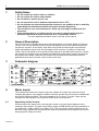
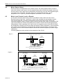
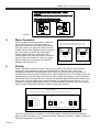
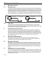
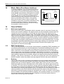
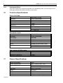
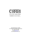
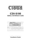
CX133 Zone Mixer
Installation & User Guide V9.0
Cloud Electronics Limited
140 Staniforth Road, Sheffield, S9 3HF England
Tel + 44 (0) 114 244 7051
Fax + 44 (0) 114 242 5462
E-mail [email protected]
Web site http://www.cloud.co.uk
1
CX133: INSTALLATION AND OPERATION MANUAL
CX133 ZONE MIXER
Installation and operation manual
Contents
Section
Page
1
Safety Notes...............................................................................2
2
General Description ...................................................................2
3
Schematic Diagram ....................................................................2
4
Music Inputs ...............................................................................2
4.1 Sensitivity & Gain Control.....................................................2
4.2 Music Source Select.............................................................3
4.3 Music Level Control, Local or Remote..................................3
5
Mono Operation .........................................................................4
6
Music Priority..............................................................................4
7
Microphone Input .......................................................................5
7.01 Microphone Input ...............................................................5
7.02 Gain Control .......................................................................5
8
Front Panel Level Controls.........................................................5
9
Microphone Equalisation ............................................................5
10
Microphone Priority ....................................................................5
11
Inhibiting Mic or Music Sections .................................................5
12
Zone outputs ..............................................................................6
12.1 Music Equalisation .............................................................6
13
Utility Output...............................................................................6
14
Music Mute (Fire Alarm Interface) ..............................................7
15
General Notes ............................................................................7
15.1 Multi-zone Applications ......................................................7
15.2 EMC Considerations ..........................................................7
15.3 Earthing..............................................................................7
15.4 Unbalanced Mode ..............................................................8
29/05/02 V9
16
Technical Specifications.............................................................8
17
General Specifications ...............................................................8
2
1
CX133: INSTALLATION AND OPERATION MANUAL
Safety Notes
•
•
•
•
•
Do not expose the unit to water or moisture
Do not expose the unit to naked flames.
Do not block or restrict any air vent
Do not operate the unit in ambient temperatures above 35oC
Do not perform any internal adjustments unless you are qualified to do so and fully
understand the hazards associated with mains operated equipment.
• The unit has no user serviceable parts. Refer any servicing to qualified service
personnel.
• If the moulded plug is cut off the lead for any reason, the discarded plug is a
potential hazard and should be disposed of in a responsible manner.
For more detailed information refer to the rear of the manual.
2
General Description
The Cloud CX133 is versatile audio mixer with applications in Licensed, Retail and Leisure
venues. The unit has facilities for three stereo line signals and one microphone signal that
can be fed, in stereo, to two areas, each with a front panel mounted music source select
switch and adjacent music level and microphone level controls. In addition, a fixed level
‘Utility’ output is provided to serve general utility areas such as toilets and foyers etc. All preset controls are located on the rear panel with additional configuration jumpers mounted on
the printed circuit board. Remote level controls can be wired to the two stereo zones for
applications that require remote control of the music level.
3
Schematic diagram
4
Music Inputs
The unit has three stereo line inputs; these are suitable for most music sources such as
compact disc players, tape players, satellite receivers and the like. All inputs are unbalanced
and use RCA phono sockets. The input impedance is 47k ohms. The Line 3 input can be
configured to have priority over any other music source, see section 6.
4.1
Sensitivity & Gain Control
All three stereo line inputs have a pre-set gain control on the rear panel adjacent to the
respective input socket. The gain control has a range of 20dB allowing the input sensitivity to
be varied from -12dBu (200mV) to +8dBu (2.0V). The pre-set gain control should be set so
that all the input signals are operating at the same level and that the front panel level control
has an optimum range of control.
29/05/02 V9
3
CX133: INSTALLATION AND OPERATION MANUAL
4.2
Music Source Select
Each zone has an independent source select control. The three position switch is used to
select the desired music signal. Use the supplied label pack to identify the signal sources on
the front panel. Line 3 input can be configured to have priority over any other selected signal,
see section 6 for full details. The Utility output can operate with the Zone 1 music
programme, Line 1 input or just the microphone; see section 13 for full details.
4.3
Music Level Control, Local or Remote
A front panel mounted music level control is provided for each of the two main zones.
Remote control of the Zone 1 and Zone 2 music level is possible by connecting a remote
level control plate (RL-1) to the 4 pole connector on the rear panel of the CX133 (see
connection diagram Figure 1 below). Either or both of the two main zones can operate in the
‘split’ mode where two remote level plates can be wired to control the left and right outputs
independently. When operating in the ‘split’ mode, the respective zone of the CX133 should
be configured to operate in the mono mode (see section 5 'Mono Operation'). The front panel
level control can be defeated by configuring the relevant internal jumpers, see Figure 3 for
full details. Use two core screened cable to connect the remote level plate (maximum length
100metres).
Full wiring details are also printed on the underside of the CX133.
Figure 1
REMOTE LEVEL CONTROL WIRING
CX133
4 POLE
RL-1
CONNECTOR
1
1
2
2
3
4
3
STANDARD WIRING CONVENTION
FOR APPLICATIONS WITH ONE RL-1 FOR EACH ZONE
USE TWO CORE SCREENED CABLE
Figure 2
LEFT OUTPUT
SPLIT MODE
LEVEL CONTROL
CX133
4 POLE
CONNECTOR
RL-1
1
1
2
RIGHT OUTPUT
LEVEL CONTROL
2
3
RL-1
4
3
1
2
3
REMOTE LEVEL CONTROL WIRING - USE TWO CORE SCREENED CABLE
SPLIT MODE - WITH INDEPENDANT CONTROL OF LEFT AND RIGHT OUTPUTS
EACH ZONE CAN BE SPLIT INTO TWO SUB ZONES
THE RESPECTIVE ZONE SHOULD BE CONFIGURED TO OPERATE IN MONO WHEN
THIS FACILITY IS UTILISED
29/05/02 V9
4
CX133: INSTALLATION AND OPERATION MANUAL
Figure 3
5
Mono Operation
MONO / STEREO OPERATION
Internal jumpers allow either zone to operate in
mono (see Figure 4). In the mono mode of
operation, both the left and right output sockets
carry the same mono signal and either or both
sockets can be used. Separate remote control of
the mono signal on the left and right output
socket can be achieved by wiring two RL-1
control plates to the 4 pin connector as shown in
Figure 2 When this feature is used, we suggest
that the respective front panel level control is
defeated (see section 4.3).
6
WHEN OPERATING IN MONO USE EITHER OUTPUT
DISCONNECT POWER BEFORE REMOVING TOP PANEL
STEREO
STEREO
MONO
J3 = ZONE 1
MONO
J1 = ZONE 2
Figure 4
Priority
When a Juke Box or Spot Announce Player is connected to the CX133, fully automatic
priority over any selected line input can be achieved by using the Line 3 input and
configuring the relevant internal jumpers (see Figure 3). When this mode of operation is
selected, the unit will operate normally until a signal is detected on line 3 and this causes the
selected signal (usually background music) to mute, allowing the signal on line 3 to operate
with priority. Once the signal on line 3 ceases, the selected signal will smoothly restore to its
former level. The time taken for the selected signal to be restored can be set at 3, 6 or 12
seconds by fitting the appropriate jumper (J5) on the printed circuit board. The line 3 priority
option can be configured to operate on either or both zone outputs.
LINE 3 PRIORITY
IMPORTANT! DISCONNECT THE POWER CABLE BEFORE REMOVING TOP PANEL
J5
LINE 3 PRIORITY
J6
J7
ZONE 1
ZONE 2
RELEASE TIME
3 SECONDS
OFF
ON
OFF
ON
LINE 3
6 SECONDS
PRIORITY
12 SECONDS
PLACE THE JUMPERS ON ONE PIN WHEN SELECTING 'OFF'
Figure 5
The Line 3 priority does not operate on the Utility Output, however we have included the
option to select the utility zone to operate with Line 3 priority if preferred – please contact our
Technical Help team for full details.
29/05/02 V9
5
CX133: INSTALLATION AND OPERATION MANUAL
7
Microphone Input
7.01
Microphone Input
A microphone input is provided and the microphone amplifier is an electronically balanced,
transformerless design configured for optimum low noise performance. The input impedance
is greater than 2kΩ and is suitable for microphones in the 200 to 600 ohm range. Input is via
a gold plated 3-pin XLR type connector with latch, which is positioned on the rear panel. For
balanced microphones, connect the cable screen to pin 1, the in phase signal to pin 2 and
the reverse phase to pin 3. To operate the channel in the unbalanced mode, connect pin 3
to pin 1 (ground) inside the XLR cable plug. Use pin 2 as hot and pin 1 as screen (ground)
Figure 6
BALANCED
1
2
MIC INPUT
TERMINATION
GROUND (SCREEN)
3
UNBALANCED
1
2
GROUND (SCREEN)
3
LINK PIN 3 TO PIN 1
REV - PHASE (-)
HOT (+)
IN - PHASE (+)
7.02
Gain Control
A pre-set gain control is provided adjacent to the XLR input connector. The gain can be
adjusted from 0dB to 60dB and this wide range of gain allows direct connection of high
output devices such as radio microphones without the need for additional attenuation. A high
overload margin is maintained at all gain settings.
8
Front Panel Level Controls.
A separate microphone level control is provided for both Zone 1 and Zone 2 and these
provide the user with a convenient means to operate the microphone at a suitable level in
the zone of their choice. The microphone signal is routed directly to the respective output
stage and is unaffected by the operation of the music level control. The gain control on the
rear panel should be set at a level where it is not possible to have excessive gain even when
the front panel level controls are fully clockwise. Self adhesive labels are provided to
customise the controls.
9
Microphone Equalisation
The microphone channel has both a fixed high pass filter and independent pre-set
equalisation controls positioned on the rear panel. The filter attenuates the signal below
100Hz and the tone controls provide ±10dB at 100Hz and 5kHz.
10
Microphone Priority
Fully automatic, voice operated priority is provided for the microphone channel. A priority
on/off switch is positioned on the rear panel. With the priority function switched on, when a
microphone signal is detected, the music signal is attenuated, allowing the message to be
clearly heard; normal music operation is restored smoothly after the announcement has
been made. Once switched on, the mic priority will operate on Zone 1, Zone 2 & the Utility
Output.
11
Inhibiting mic or music sections
If the CX133 is required to provide a microphone signal, without any music programme, the
mixer can be configured to operate with the music channel disabled by simply removing the
two resistors R72 & R162 for zone 1 and R54 & R55 for zone 2. If there is a requirement to
operate either zone with the microphone channel disabled, remove R68 & R138 for zone 1
and R50 & R164 for zone 2.
29/05/02 V9
6
12
CX133: INSTALLATION AND OPERATION MANUAL
Zone Outputs
The two stereo output zones have balanced output stages using 3 pin XLR type connectors
and can operate into loads as low as 600Ω. The nominal output level is 0dBu (775mV) but
the CX133 can operate with a wide range of signal levels up to a maximum output of +20dBu
(7.75V). A 3-pin XLR type female connector is required for each output.
OUTPUT
BALANCED
GROUND (SCREEN)
REV - PHASE (-)
IN - PHASE (+)
2
1
3
TERMINATION
UNBALANCED
GROUND (SCREEN)
2
1
3
NO CONNECTION TO PIN 3
HOT (+)
Figure 7
For balanced interconnections, 2-core screened cable should be used. Connect the cable
screen to pin 1. Pin 2 is the in phase signal (normally red) and pin 3 is the reverse phase
signal (normally blue or black). If you plan to connect any zone output to an unbalanced
load, see section 15.4 'Unbalanced Mode'. Full connection details are printed on the
underside of the CX133.
12.1
Music Equalisation
Both Zone 1 and Zone 2 have separate pre-set treble and bass controls for the music signals
only. These pre-set controls are located on the rear panel adjacent to the respective zone
output sockets. The music treble control has a range of ±10dB at 10kHz and the music bass
control operates with a range of ±10dB at 50Hz.
13
Utility Output
The CX133 is fitted with a fixed level, balanced output primarily intended to provide a mono
signal for utility areas such as toilets and foyers where it is desirable to feed a music + mic
programme at a constant level, totally independent of the variable programmes of Zone 1&2.
Figure 8
The utility output has a choice of three input sources, selected by a PCB mounted jumper.
The CX133 leaves the factory configured to provide a music signal derived from the Zone 1
music source selector (pre-level control). Alternatively, the jumper J8 can be set to source
the music signal directly from the Line 1 input (see Figure 8). A pre-set microphone level
control, positioned adjacent to the output socket can be set to provide microphone signals at
the optimum level; if the priority function is switched on, the music signals will attenuate
when an announcement is made. If the music source jumpers are removed, the output can
be used as a microphone only signal to serve areas requiring music free announcements.
29/05/02 V9
7
CX133: INSTALLATION AND OPERATION MANUAL
14
Music Mute (Fire Alarm Interface)
15
15.1
REMOTE MUSIC MUTE TERMINATIONS
CX133
2 POLE
CONNECTOR
RELAY
In certain installations, such as licensed premises or
retail outlets within a shopping mall, there may be a
local authority or fire service requirement to mute the
music signals via a fire alarm control panel in an alarm
condition. The CX133 provides a facility to mute the
music signals only, by using a fully isolated pair of
contacts (usually a relay mounted close to the CX133
which is powered by the fire alarm control panel)
which should close during an alarm condition (the
installation of this relay is normally undertaken by the
fire alarm installation company). The front panel
mounted 'Music Mute' LED will illuminate to indicate
the operation of the mute circuit.
1
2
THE RELAY CONTACT MUST BE VOLTAGE
FREE AND FULLY FLOATING
Figure 9
General Notes
Multi-zone Applications
Where the sound system specification calls for separate control in more than 2 zones, the
CX133 can be used in multiples. The signal sources can be connected to several inputs as
required but care must be taken to ensure that the output stage of the signal source is
capable of driving a lower impedance load. The impedance of the line input stage is 47kΩ
and it would be reasonable to assume that most op-amp based signal sources should drive a
10kΩ load, thus allowing up to five parallel circuits. The input impedance of the microphone
amplifier is 2.4kΩ making it suitable for a microphone with a maximum impedance of 600Ω.
A single 200Ω microphone could therefore be connected to three balanced inputs. To avoid
any problems associated with differences in mains supply earthing, we recommend that all
the CX133's used in a multi-zone application should be located close together and
connected to a common mains supply.
15.2
EMC Considerations
The CX133 fully conforms to the relevant electromagnetic compatibility (EMC) standards and
is technically well behaved; you should experience no problems interfacing the unit to other
items of equipment and under normal circumstances no special precautions need to be
taken. If the unit is to be used within close proximity to potential sources of HF disturbance
such as high power communication transmitters, radar stations and the like, it is suggested
that the cable screen be connected to the shell of the XLR type connector and the line input
signal leads be kept as short as possible. Always use balanced interconnections wherever
possible. If the CX133 is mounted in a 19” rack, do not locate the unit in close proximity to a
powerful amplifier, which may radiate a strong magnetic field from the power transformer.
15.3
Earthing
The 0V rail of the CX133 is coupled to the chassis ground by a parallel resistor/capacitor
network and no interconnection problems should be encountered. When several mains
powered units are connected together via their signal cables, there is a risk of one or more
earth loops which may cause an audible hum on the system even with the gain controls set
to minimum. The 'hum' can be remedied in several ways; the preferred method is to operate
the output links to the power amplifiers in the balanced mode, with the cable screen only
connected at the receiving end (amplifier input). The signal source units should be located as
close as possible to the CX133 and the metal housing of the various units should not be
electrically connected together through the equipment rack. If this is a problem, rack isolating
kits are available from specialist hardware suppliers. If the problem persists, try to connect all
the interconnected units, including the power amplifiers to a common power source to
ensure that a common ground is provided.
29/05/02 V9
8
15.4
CX133: INSTALLATION AND OPERATION MANUAL
Unbalanced Mode
If the zone outputs are required to operate in the unbalanced mode, the unused pin of the
XLR type connector should be left with no connection.
16
Technical Specifications
Stereo Line Input
Frequency response
Distortion
Sensitivity
Input impedance
Input gain
Headroom
Noise
Equalisation
20Hz-20kHz ±0.5dB
<0.03% 20Hz-20kHz
-12dBu(200mV) to +8dBu(2.0V)
47kΩ
±10dB
>20dB
-90dB (0dB gain) rms 22Hz – 22kHz
HF ±10dB 10kHz
LF ±10dB 50Hz
Microphone Inputs
Frequency response
Distortion
Gain range
Input impedance
Common mode rejection
Headroom
Noise
Equalisation
100hz -3dB(filter) 20kHz ±0.5dB
<0.02% 20Hz/20kHz
0dB-60dB
>2kΩ (balanced)
>70dB 1kHz
>20dB
-128dB EIN 22Hz-22kHz (150Ω)
HF ±10dB 5kHz
LF ±10dB 100Hz
Zone outputs & Utility output
Nominal output level
Minimum load impedance
Maximum output level
17
General Specifications
Power consumption
Power requirements
Fuse rating
Fuse type
Width
Height
Depth
Weight
29/05/02 V9
0dBu balanced
600Ω
+20dBu
12VA
230V ± 10% or 115V ± 10%
T50mA H for 230V input
T100mA H for 115V input
20mm x 5mm 250V
482.60mm
44.00mm
160mm + connectors
3.50kg including packing
CX133: INSTALLATION AND OPERATION MANUAL
This product conforms to the following European EMC Standards:
BS EN 55103-1:1997
BS EN 55103-2:1997
This product has been tested for use in commercial and light industrial environments. If the equipment
is used in controlled EMC environments, the urban outdoors, heavy industrial environments or close to
railways, transmitters, overhead power lines etc. the performance of the unit may be degraded.
The product conforms to the following European electrical safety standard.
BS EN 60065:1998
Safety Considerations and Information
The unit must be earthed. Ensure that the mains power supply provides an effective earth
connection using a three wire termination.
When the mains switch is in the off position the live and neutral conductors of the mains
transformer are disconnected.
CAUTION – Installation
Do not expose the unit to water or moisture
Do not expose the unit to naked flames.
Do not block or restrict any air vent
Do not operate the unit in ambient temperatures above 35oC
CAUTION - Mains Fuse
Replace the mains fuse only with the same type and rating as marked on the rear panel. The
fuse body size is 20mm x 5mm.
CAUTION – Servicing
The unit contains no user serviceable parts. Refer servicing to qualified service personnel. Do
not perform servicing unless you are qualified to do so.
Disconnect the power cable from the unit before removing the top panel and do not make any
internal adjustments with the unit switched on.
Only reassemble the unit using bolts/screws identical to the original parts
In the interest of continuing improvements Cloud Electronics Limited reserves the right to alter
specifications without prior notice.
Cloud Electronics Limited 140 Staniforth Road Sheffield S9 3HF England
Telephone +44 (0) 114 244 7051 Fax +44 (0) 114 242 5462 E-mail: [email protected]
29/05/02 V9
9