1
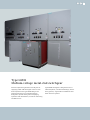
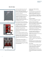
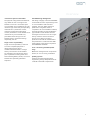
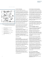
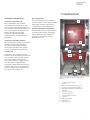
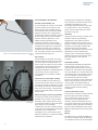
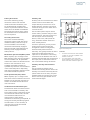
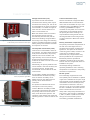
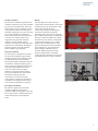
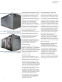
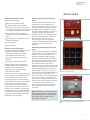
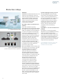
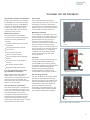
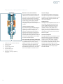
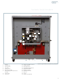
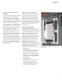
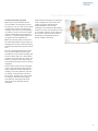
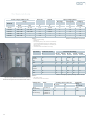
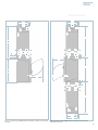
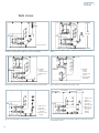
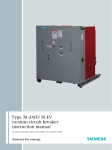
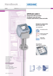
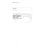
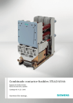
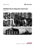
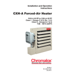
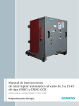
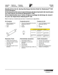
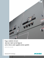
Type GM38 38 kV
metal-clad switchgear
selection and application guide
E50001-F710-A124-X-4A00
Answers for energy.
Table of contents
Overview
4–6
Construction
7–12
Accessories
13
Protective relays
14
Vacuum circuit breakers
15–21
Technical data
22–25
Dimensions
26–29
Side views
30
Notes
31
Type GM38
Medium-voltage metal-clad switchgear
Siemens’ experience gained in over 80 years of
supplying metal-clad switchgear in the U.S. has
been captured in the type GM38 design. The
objective has been to incorporate features
designed to provide safety, while simplifying
operation and maintenance, as well as minimizing
installation cost.
Type GM38 switchgear is designed for use in
industrial plants, commercial buildings, electric
utility systems, cogeneration installations and
other electrical systems.
Overview
Siemens type GM38 38 kV metal-clad
power switchgear assemblies with
horizontal drawout type 38-3AH3
vacuum circuit breakers take advantage
of the latest developments in vacuum
interrupter technology.
Voltage transformers (VTs) with their
associated drawout primary fuses can be
located in the cell above a 1,200 A or
2,000 A circuit breaker, allowing
significant space savings. Siemens
introduced this feature to the 38 kV
switchgear market with the launch of the
type GM38 design in 1993.
Front
The equipment meets or exceeds the
latest standards of ANSI, IEEE and NEMA.
Type GM38 switchgear is designed for
use in industrial plants, commercial
buildings, electric utility systems,
cogeneration installations and other
electrical systems. It is commonly used
for protection and switching of
transformers, capacitors, buses,
distribution feeder lines and, in general,
for protection of any medium-voltage
power circuit.
Side (barrier removed)
Siemens experience gained in over 80
years of supplying metal-clad switchgear
in the U.S. has been captured in the type
GM38 design. The objective has been to
incorporate features designed to provide
safety, while simplifying operation,
maintenance and minimizing installation
cost.
The switchgear structure and the
drawout vacuum circuit breaker are an
integrated design, with dielectric,
thermal and interruption integrity built
directly into the basic design, not added
as an afterthought.
Rear
Figure 1: Type 38-3AH3 circuit breaker
4
Siemens type 3AH3 operating
mechanism
The type 38-3AH3 circuit breaker uses
the proven Siemens type 3AH3 storedenergy operating mechanism. This
operator is an evolution of the type 3A
family of operators first introduced in
1976. Over 60,000 type 3AH3 operating
mechanisms have been produced since
1998.
Faster interruption
Standard interrupting time is 5-cycles,
with an option available for 3-cycles.
Siemens vacuum interrupters
The vacuum interrupters used in the type
3AH3 circuit breaker are manufactured by
Siemens and have been proven in
thousands of installations since 1976.
The chrome-copper contact design used
in these vacuum interrupters assures low
chopping levels, eliminating the need for
surge protection on most circuits.
Front mounted operating mechanism
The simple type 3AH3 operating
mechanism makes maintenance and
inspection easy. The mechanism is
located on the front of the circuit breaker,
rather than underneath.
Maintenance intervals
If applied under ANSl “usual service”
conditions, maintenance of the circuit
breaker mechanism is only needed at five
year intervals.
Maintenance of the switchgear cubicle is
recommended at five year intervals and
primarily consists of cleaning insulation.
Floor rollout
No lift truck or dolly is needed to insert or
remove circuit breakers or drawout fuse
trucks in the lower cell of switchgear
located at floor level. For indoor
switchgear located on a raised
“housekeeping” pad or for outdoor nonwalk-in switchgear, a lift truck is required
to handle circuit breakers or drawout fuse
trucks.
Overview
“Universal” spare circuit breaker
Full ANSI design background
The physical configuration and interlock
logic allow the use of a single circuit
breaker to serve as a “universal” spare
circuit breaker at an installation site. The
interlock logic checks the principal rating
characteristics (continuous current,
maximum voltage and interrupting
current) and allows a circuit breaker to be
inserted in any circuit breaker cell,
provided that the ratings of circuit
breaker equal or exceed the ratings
required by the cell.
Full design integrity is assured. ANSl/IEEE
C37.09 and C37.20.2 require design tests
on circuit breakers and structures
together. The type 3AH3 operator is
produced in our global center of
competence for circuit breakers in Berlin,
and final assembly of both the drawout
type 38-3AH3 circuit breaker and the
switchgear structures occurs in a single
facility. Siemens controls the entire
process, from design concept to
production. Records are maintained to
and production is certified to ISO 9001
requirements to document compliance
with ANSl/IEEE standards.
Single source responsibility
Single source responsibility is assured
since the complete equipment is
designed by Siemens and is
manufactured and tested in a single
facility. The vacuum circuit breakers
are checked in the switchgear cells as
part of production testing. After tests
and interchangeability checks, the circuit
breakers are separately packed for
shipment.
UL or C-UL Listing available (40 kA
only)
Where the arrangement of components
allows, UL or C-UL Listing is available.
Quality systems
Facilities involved with application,
engineering, design and production are
certified to ISO 9001 requirements.
5
Overview
1
3
2
6
7
8
5
4
8
Figure 2: Circuit breaker cell (1,200 A or 2,000 A)
with VT auxiliary (3,000 A similar except upper
cell reserved for fan-cooling equipment)
1.
2.
3.
4.
5.
6.
7.
8.
Drawout primary CL fuses for VTs
VTs (stationary)
Upper door for protective relays,
instruments, etc.
Type 38-3AH3 vacuum circuit breaker
Lower door (blank)
Copper main bus 1,200 A, 2,000 A or
3,000 A self-cooled
Power cable termination area
CTs
Structural flexibility
Circuit breaker interchangeability
Siemens type GM38 metal-clad
switchgear provides enhanced flexibility
in locating circuit breaker, auxiliary and
metering cells within the structure layout.
Circuit breakers are located in the lower
cell positions. The upper cell position can
be used for voltage transformers with the
associated drawout primary fuses.
The type GM38 switchgear cubicle and
the drawout type 38-3AH3 circuit breaker
element are both built to master fixtures,
so circuit breakers of the same ratings are
interchangeable with each other even if
the circuit breaker is required for use with
a cell with “provisions only” supplied
years earlier. The type 38-3AH3 circuit
breaker is interchangeable with the type
38-3AF circuit breaker, provided the
ratings are equal. The type 38-3AF circuit
breaker is not interchangeable with the
40 kA type 38-3AH3.
Each vertical section contains the main
bus bar compartment, plus a rear
compartment for incoming and outgoing
connections. The front portion of the
vertical section contains an upper cell for
auxiliary devices, VTs or drawout primary
fuses for a control power transformer
(CPT) located in the lower cell.
The front portion of the vertical section
contains a lower cell for circuit breaker,
auxiliary devices, VTs, CPT (if primary
fuses are located in upper cell) or
drawout primary fuses for a CPT located
in the rear of the section.
Circuit breaker cells include primary and
secondary disconnects, current
transformers (CTs) and secondary wiring,
as necessary. Instruments, protective
relays and power meters along with their
secondary wiring and other components
are located in the upper cell. The
switchgear is normally designed so that
additional vertical sections may be added
in the future.
Enclosure design
The type GM38 design includes full ANSI/
IEEE C37.20.2 metal-clad construction.
This means complete enclosure of all live
parts and separation of major portions of
the circuit to retard the spread of faults to
other compartments. Removable plates
permit access to all compartments. The
rear panels are removable to allow access
to outgoing cable connections.
The structure is constructed of bolted
steel for better dimensional control than
with welded designs. Sheet steel interunit barriers extend the full height and
depth of each vertical section for
isolating adjacent sections. The ground
bus extends the entire length of the
complete switchgear lineup and to each
circuit breaker cell.
6
A circuit breaker of higher rating can be
used in a cell of equal or lower rating,
i.e., a 2,000 A 40 kA type 38-3AH3 circuit
breaker can be used in a 1,200 A 31.5 kA
type 38-3AH3 or type 38-3AF circuit
breaker cell.
Tested to ANSl/IEEE standards
Siemens type GM38 switchgear is tested
to meet the requirements of ANSl/IEEE
standards. A complete design test
program, including short-circuit
interruption, load-current switching,
continuous current, mechanical
endurance, close and latch current, shorttime and momentary withstand, impulse
withstand and the other tests required by
the standards, has been successfully
completed.
These tests encompass the complete
equipment design, including both the
switchgear structure and the circuit
breaker removable element. Production
tests in accordance with ANSl/IEEE
standards are performed on every group
of switchgear and on each circuit breaker.
Certified copies of test data can be
furnished to customers upon request.
The switchgear is not classified as arcresistant switchgear and has not been
tested for resistance to internal arcing per
ANSI/IEEE C37.20.7. Qualification to
seismic requirements of various codes
(for instance, IBC-2006, UBC, IEEE 693,
etc.) is available. Consult your local
Siemens representative with detailed
requirements.
UL or C-UL Listing available
When specified, if the component
configuration allows, the switchgear
rated 40 kA can be provided with the UL
or C-UL (for use in Canada) Listed label,
indicating conformance to the
requirements of ANSl/IEEE C37.54 and
ANSI/IEEE C37.55.
Construction
Switchgear compartments
Bus compartment
Vacuum circuit breaker cell
The bus compartment is a separately
enclosed space for three-phase insulated
main power bus bars, supports and
connections to circuit breaker cells.
The circuit breaker cell is a bolted,
reinforced sheet steel enclosure, with
provisions for a type 38-3AH3 vacuum
circuit breaker. It includes a hinged front
door, inter-compartment and inter-unit
barriers, primary and secondary
disconnects, racking mechanism,
interlocks and CTs, as required by the
application.
7
Primary termination compartment
The rear area of the unit includes space
for connecting incoming or outgoing
power cables, bus duct connections,
transformer connections or surge
protection devices.
5
2, 4, 6
Vacuum circuit breaker element
9
The type 38-3AH3 vacuum circuit breaker
includes a stored-energy operating
mechanism, primary and secondary
disconnects, auxiliary switch, ground
contact, control wiring and interlocks.
1
1
12
8
3
Auxiliary cell
An auxiliary cell is similar to a circuit
breaker cell, except without provisions for
a circuit breaker. Space may be used for
VTs, a CPT, drawout primary fuses or
other auxiliary devices. Opening of the
front door does not automatically
disconnect a drawout primary fuse truck
located inside the cell. Instruments and
protective relays can be located on the
front door of an auxiliary cell.
2, 4, 6
9
11
10
12
Figure 3: Two views of same circuit breaker cell
interior
1.
2.
3.
4.
5.
Shutter operating linkage
Shutters
Racking mechanism padlock provisions
Primary disconnects (behind shutters)
Mechanism operated cell (MOC) switch
(optional)
6. CTs (behind barrier)
7. Secondary disconnect
8. Trip-free padlock provisions
9. CT barrier
10. Racking mechanism
11. Ground bar
12. Rating interlocks
7
Construction
Circuit breaker cell features
Vacuum circuit breaker cell
Figure 4: Circuit breaker being racked out with door
closed
A circuit breaker cell consists of a bolted,
reinforced sheet steel enclosure, with
provisions for a type 38-3AH3 vacuum
circuit breaker. The cell includes a blank
hinged front door, inter-compartment
and inter-unit barriers, stationary primary
and secondary disconnects, automatic
shutters, drawout guide rails, circuit
breaker racking mechanism and
necessary interlocks. Control wiring,
terminal blocks and CTs are provided as
needed for the application. Instruments
and protective relays are mounted as
needed on the front panel of the upper
cell. Secondary control circuit cutouts are
located inside the upper cell.
Floor rollout
Circuit breakers in the lower cell can be
rolled out directly on the floor in front of
the unit without a handling device, lift
truck or hoist for indoor (if not on raised
“housekeeping” pad) and Shelter-Clad
installations. A lift truck accessory is
optionally available for handling drawout
primary fuse trucks in upper cells, or
circuit breakers in non-walk-in outdoor
enclosures.
Closed door circuit breaker racking
The circuit breaker can be racked in or
out with the cell door open or closed. The
mechanism includes an indicator to show
the racking mechanism position with the
door closed. For racking, a manual drive
crank or an optional electric motor drive
may be used.
Electrical racking accessory (optional)
Figure 5: Electrical racking accessory mounted on the
switchgear
8
An electrical racking motor accessory is
available. This consists of a motor drive
assembly, which installs (without tools)
on mounting brackets on the switchgear
front panel of a circuit breaker
compartment. The unit includes a power
cord, which can be plugged into a duplex
receptacle in the vicinity of the
switchgear, plus a control cable, which
allows the operator to control the racking
operation from a distance.
An alternative arrangement is available,
which includes a control box that can be
mounted at a distance from the
switchgear and permanently connected
to control power. In turn, the racking
motor can be connected to the control
box with a long cord.
Interlocks
Interlocks prevent moving a closed circuit
breaker in the cell by preventing
engagement of the racking crank (or
electric racking accessory) if the circuit
breaker is closed. A second interlock lever
holds the circuit breaker mechanically
and electrically trip-free between
positions. The racking mechanism can be
padlocked to restrict unauthorized
racking of the circuit breaker. Separate
padlock provisions may be used to hold
the circuit breaker in the trip-free
condition.
Automatic shutters
Automatically operated grounded steel
shutters allow or block access to the
stationary primary disconnects in circuit
breaker cells. The shutters are opened by
the circuit breaker as it moves toward the
connected position. The shutters close as
the circuit breaker is racked away from
the connected position to the test
position. The shutters remain closed until
they are forced open by insertion of the
circuit breaker. This design enhances
protection for personnel, as compared to
shutters, which link to the racking
mechanism.
Current transformers (CTs)
Front-access CTs may be mounted around
both the upper and lower stationary
primary disconnect bushings. Up to a
total of four CTs per phase may be
located in each circuit breaker cell, two
on the bus side and two on the load side,
around the primary disconnect bushings.
The CTs may be standard accuracy (type
MD38) or optional special accuracy (type
MDD38).
Wiring
Secondary wiring is neatly bundled and
secured on the sides of the cell. Wiring is
not routed on the floor of the switchgear.
Construction
Primary disconnects
Auxiliary cells
The cubicle stationary primary
disconnect contacts are recessed
inside the insulator assemblies, and
are located behind grounded steel
shutters to prevent accidental contact
when the circuit breaker is withdrawn.
The primary disconnect finger clusters
are mounted on the circuit breaker for
ease of inspection.
Auxiliary cells are constructed in a similar
manner as the circuit breaker cells,
except without provisions for a circuit
breaker element. Auxiliary cells may be
located in the upper cell or lower cell of
a vertical section.
Secondary disconnects
The cubicle mounted stationary
disconnect contacts mate with spring
loaded secondary contacts on top of
the circuit breaker. The secondary
disconnects automatically engage in
both the test and connected positions,
and they remain engaged between
these positions.
Mechanism operated cell (MOC) switch
When required, up to 24 stages of the
MOC auxiliary switch can be mounted in
the circuit breaker cell. All spare MOC
contacts are wired to accessible terminal
blocks for user connections. As a
standard, these MOC switches are
operated only when the circuit breaker is
in the connected position. Optionally,
they may be arranged to operate in both
the connected and test positions.
Truck operated cell (TOC) switch
When required, up to 12 stages of the
TOC switch can be mounted in the circuit
breaker cell. All spare TOC contacts are
wired to accessible terminal blocks for
user connections.
The front door panels may be used to
mount meters, protective relays or other
instrumentation. The interior portion of
the cell may be used for mounting
devices, such as VTs, CPTs (lower cell
only), automatic transfer switches or
other auxiliary devices.
For ease in operation, primary current
limiting fuses for CPTs and VTs are
arranged in a drawout configuration,
while the heavy transformers are
stationary. This greatly reduces the effort
required to isolate transformers for
inspection or maintenance. The racking
mechanism for the drawout fuse truck is
manually operated with the compartment
door open, but it is otherwise similar to
the circuit breaker racking mechanism.
1
2
Figure 6: Auxiliary cells
Footnotes:
1. For VTs or rollout fuses for a CPT located
in lower cell, or for fan if 3,000 A circuit
breaker in lower cell
2. For circuit breaker, VTs, rollout fuses
for CPT located in rear or remote, or CPT
when rollout fuses located in upper cell.
Auxiliary cell relay and instrument
space
The front panel of auxiliary cells is
suitable for mounting devices. Even if the
auxiliary cell contains rollout tray devices
(rollout fuses for VTs or CPTs), the space
available allows for mounting any of the
devices commonly specified for use on
metal-clad switchgear.
Unobstructed terminal block space
Terminal block areas are located on each
side of circuit breaker or auxiliary cells.
Since racking system components are not
mounted on the cubicle sides, the sidemounted terminal blocks are not
obstructed as in other designs.
Installation of field wiring is simplified, as
wiring can be easily laid directly against
the side sheets. It is not necessary to
“fish” the wiring under, around and
through obstructions.
9
Construction
Figure 7: Primary CL fuses accessible when fuse truck
in disconnect position and access door open
Voltage transformers (VTs)
Current transformers (CTs)
Up to three VTs with their drawout
mounted current limiting fuses may be
mounted in an auxiliary cell. VTs can be
accommodated in the upper cell above a
circuit breaker, or in either the upper or
lower cells of a section that does not
have a circuit breaker cell.
Siemens toroidal CTs comply with ANSI/
IEEE standards and are mounted at the
rear of the circuit breaker cell. Up to four
standard accuracy type MD38 or special
accuracy type MDD38 CTs may be
mounted on each phase: two on the bus
side and two on the load side around
the primary disconnect bushings. CTs
may be added or changed with the cell
de-energized without removing bus bar
or cable connections. Multi-ratio CTs are
available.
When the drawout fuses are moved to
the disconnect position, they are
automatically disconnected, and the
transformer windings are grounded to
remove any static charge. An insulating
shutter is provided, arranged to operate
before primary fuses become accessible
for inspection or removal.
Control power transformers (CPTs)
CPTs can be accommodated in either of
two manners. For single-phase and small
three-phase transformers, the primary
drawout fuses can be located in the
upper auxiliary cell of a vertical section,
and the fixed-mounted CPT can be
located in the lower front cell of the same
vertical section.
Alternatively, the primary drawout fuses
can be located in the lower auxiliary cell
of a vertical section, and the fixedmounted CPT can be located in the rear
of the section.
Figure 8: VT cell with fuse truck withdrawn (shutter
closed, VT primaries grounded)
The secondary molded case breaker is
interlocked with the drawout primary
fuses so that the secondary circuit
breaker must be open before the CPT
primary can be disconnected or
connected.
This prevents accidental load-current
interruption on the main primary
contacts. With the secondary molded
case breaker open and the latch released,
the primary fuse truck can be moved
easily to the disconnect position. The
operation of the drawout fuse truck and
insulating shutter is similar to that for the
VTs.
Figure 9: Fuse truck on extension rails
10
Primary termination compartment
The primary termination compartment at
the rear of the switchgear section is
separated from all other compartments
by barriers. This space can be used for
connecting power cables, bus duct or for
connection to an adjacent power
transformer (PT). Surge arresters may
also be provided in this compartment.
Bolted rear plates are provided as
standard to provide access to the cable
area for each unit. Hinged rear doors are
available as an option.
Infrared (IR) viewing windows are
optionally available for use in checking
temperature of conductors in the primary
termination compartment.
Bus bar system
Full-round-edge copper bus bar with
silver-plated joints is standard. Tin-plated
copper bus is available as an option. High
strength grade 5 steel hardware with split
lock washers assures constant pressure,
low-resistance connections. A 0.25 in.
(6 mm) x 2.0 in. (51 mm) copper ground
bus bar is standard in all vertical sections
and is accessible at each end of the
lineup and in the primary termination of
each section. The main bus is available in
1,200 A, 2,000 A or 3,000 A self-cooled
ratings. The main bus bar system is
enclosed by grounded metal barriers.
Construction
Bus bar insulation
Wiring
Bus bars are insulated using heat-shrink
insulation. Bolted bus joints are insulated
by pre-formed molded boots, which are
held in place by nylon hardware. For bus
configurations where no boot design is
available, taped joints are used. The main
bus is supported with cycloaliphatic
epoxy inserts where the bus passes from
one section to another. Other bus is
supported using porcelain standoff
insulators. Circuit breaker support
insulators and cubicle primary disconnect
supports are molded epoxy. Interphase
and other barriers are track-resistant,
flame retardant glass polyester.
The secondary and control wiring is
connected to terminal blocks, which have
numbered points for identification. One
side of the terminal blocks for
connections leaving the switchgear is
reserved for external connections.
Secondary and control wire is minimum
No. 14 AWG, extra-flexible, stranded type
SIS wire, insulated for 600 volts, except
when devices (for instance, transducers,
communicating devices, etc.) require
different wire. Insulated barrel, crimptype locking fork terminals are used for
most applications, except where the
devices require a different type of
terminal. Where they pass through
primary compartments, secondary
control wires are armored or enclosed in
grounded metal wire covers or sheaths.
Bus joint insulation
For normal joint configurations, bolted
bus joints are insulated by pre-formed
molded polyvinyl boots (double), which
are held in place by nylon hardware.
Preformed insulating materials eliminate
the need for molding and taping joints
when connecting shipping groups in the
field, reducing installation time and
costs. The same preformed, highdielectric strength joint boots used in
factory assembly are also used in field
assembly of shipping-split bus
connections. For uncommon joint
configurations, taped joint insulation is
used. Boots for insulating user’s power
connections are available as an option.
Figure 10: Main bus construction
Figure 11: Cell wiring
Bus support insulation
Bus bars are supported on porcelain
standoff insulators using a glasspolyester saddle-clamp system. Inter-unit
bus is supported on cycloaliphatic epoxy
inserts mounted in a glass-polyester
sheet.
11
Construction
Instrumentation and protective relays
Shelter-Clad design – single aisle
Instruments, meters and protective relays
can be traditional switchboard type or
modern electronic type, depending on
the requirements of the specification. If
traditional electromechanical devices are
used, they have semi-flush cases with
dull black covers. Indicating and
recording instruments, meters and
protective relays are of the rectangular
type, semi-flush mounted. All scales have
a suitable range and are designed with
black letters on a white background.
The Shelter-Clad switchgear consists of
indoor type circuit breaker and auxiliary
cubicles located in a weatherproof steel
housing having an operating aisle space
of sufficient size to permit withdrawal of
the circuit breakers for inspection, test or
maintenance. An access door is located at
each end of the aisle, arranged so that
the door can be opened from the inside
regardless of whether or not it has been
padlocked on the outside. The aisle space
is provided with incandescent lighting,
which is controlled by means of a threeway switch at each access door. Each
cubicle includes necessary space heaters.
Each lineup includes two utility duplex
receptacles, one at each aisle access
door, for use with electric tools,
extension cords, etc. The weatherproof
enclosure for the aisle-way is shipped
disassembled for erection in the field.
Optionally, for single-aisle configurations,
the aisle portion of the enclosure can be
shipped assembled.
Control and instrument switches
Figure 12: Shelter-Clad type GM38 lineup (aisle
portion not shown - refer to Figure 13)
Switches furnished are rotary,
switchboard type and have black handles.
Circuit breaker control switches have
pistol-grip handles, while instrument
transfer switches have round notched
handles, and auxiliary or transfer
switches have oval handles.
Circuit breaker control switches have a
mechanical flag indicator showing a red
or green marker to indicate the last
manual operation of the switch.
Outdoor housings
Figure 13: Shelter-Clad single-aisle braced for
shipment
Two types of outdoor housing – nonwalk-in and Shelter-Clad – are available to
meet almost any application. For both
types, the underside of the base is coated
with a coal tar emulsion. The switchgear
is shipped in convenient groups for
erection in the field.
Non-walk-in design
12
The non-walk-in switchgear consists of
indoor type circuit breaker and auxiliary
cubicles located in a steel housing of
weatherproof construction. Each vertical
section has a full height exterior front
door with provision for padlocking. Each
cell is also equipped with an inner hinged
front door for mounting protective relays,
instrumentation and control switches.
Two removable rear panels are included
for cable access to the primary
termination area. Each cubicle includes
necessary space heaters, a switched lamp
receptacle for proper illumination of the
cubicle during maintenance and
inspection and a duplex receptacle for
use with electric tools. A molded-case
circuit breaker for space heaters is
located in one cubicle.
Shelter-Clad design – common aisle
The Shelter-Clad common-aisle
switchgear consists of two lineups of
indoor type circuit breaker and auxiliary
units located in a weatherproof steel
housing having a common operating
aisle space of sufficient size to permit
withdrawal of the circuit breakers for
inspection, test or maintenance.
Otherwise, the construction is as
described for single-aisle design, except
that the aisle portion is always shipped
disassembled for erection in the field.
Accessories
Standard accessories include:
Manual racking crank
Manual spring charging crank
Drawout extension rails (facilitate
handling of circuit breakers in outdoor
non-walk-in switchgear or drawout fuse
trucks when located above floor level)
Lifting sling (for circuit breakers or
drawout fuse trucks located above floor
level)
Split plug jumper (standard unless test
cabinet is furnished)
Contact lubricant
Touch up paint.
Optional accessories include:
Lift device (facilitate handling of circuit
breakers in outdoor non-walk-in
switchgear or drawout fuse trucks
when located above floor level)
Test cabinet (in place of split plug
jumper)
Test plugs (if required by devices)
Electric racking motor assembly (to
enable racking while operator is at a
distance from the switchgear)
Manually or electrically operated
ground and test device.
Test provisions, either a split plug jumper
or a test cabinet, are available for testing
the circuit breaker outside its cubicle.
The split plug jumper is used to bridge
the secondary disconnects with a flexible
cable, so the circuit breaker may be
electrically closed and tripped with the
control switch on the instrument panel
while the circuit breaker is outside of its
compartment. The test cabinet, including
a control switch, is used for closing and
tripping the circuit breaker at a location
remote from the switchgear.
Manually operated ground and test
device
This is a drawout element that can be
inserted into a circuit breaker cell. It
opens the shutters, connects to the cell
primary disconnecting contacts, and so
provides a means to make the primary
disconnect stabs available for testing. It is
suitable for high-potential testing of
outgoing circuits of the switchgear main
bus or for phase-sequence checking. It
also provides a means to connect
temporary grounds to de-energized
circuits for maintenance purposes. Either
three-stud or six-stud devices are
available.
Electrically operated ground and test
device
An electrically operated ground and test
device includes a power operated switch
(derived from a type 38-3AH3 circuit
breaker) arranged to allow grounding
one set of disconnect stabs. Two devices,
one each for the upper and lower stabs,
are required if grounding is desired to
either side of the unit. The device
includes test ports to allow for testing for
presence of voltage on both the line side
and the load side of the cell. The device
also provides a means of access to the
primary circuits for high-potential tests or
for phase-sequence checking. These
devices are able to close and latch against
short-circuit currents corresponding to
the ratings of the equipment. Due to the
unique requirements frequently involved
in such devices, all applications of
electrically operated ground and test
devices should be referred to Siemens
for review.
Figure 14: Manually operated ground and test device
with doors open and closed
Note: Each user must develop definitive
operating procedures for incorporating
safe operating practices. Only qualified
personnel should be allowed to use
ground and test devices.
Figure 15: Electrically operated ground and test
device
13
Protective relays
SIPROTEC™
System advantages one bay, one unit
SIPROTEC has established itself across the
market as the standard for numerical
protective relaying. Besides the common
system platform and the unique type
DIGSI 4 service interface that may be
used for all protective devices, it also
supports the new IEC 61850
communication standard.
The type SIPROTEC 4 protective relay
family offers fully integrated protection,
control, monitoring and automation
functions incorporated in a single device.
For many applications, this product
contains all the functions you need to
meet all your protection and control
requirements with just one unit per
section, saving on investment and
installation costs and enhancing
availability.
IEC 61850 – what it is and what it can
achieve?
Figure 16: Type SIPROTEC numerical
multifunction protective relays
Figure 17: Type GM38 low-voltage
protective relay and instrument compartment
Users and manufacturers jointly
developed the new international standard
IEC 61850, which was approved in early
2004. The agreed aim of this standard is
to arrive at a complete communication
solution for substations, thus providing
users with interoperability among
different makes on the basis of Ethernet
technology. This opens up a whole new
dimension in efficient substation
management. Not only short-term
savings in operation and maintenance,
but also simplified engineering, less
complexity and long-term expandability
can make you one of the winners in
tomorrow’s power market.
With type SIPROTEC protective relays and
bay control units from Siemens, we offer
all the advantages of an expert and
innovative partner in the field of
protective relaying and substation
automation. We bring you attractively
priced intelligent solutions by paying
particular attention to lowering your life
cycle and system management costs.
These solutions are the first ones
available on the market with the
international IEC 61850 standard.
To enable you to profit from these
advantages as quickly as possible,
Siemens collaborated in the preparation
of this international standard and made
every effort to ensure no time was lost in
bringing it out. The result is certainly
worth a look, because type SIPROTEC and
other power automation products and
Siemens systems are available on the
basis of the IEC 61850 standard and can
even be retrofitted in systems supplied
since 1998.
14
Type DIGSI 4 – one tool for all tasks and
products
Type DIGSI 4 is a computer program
designed for all type SIPROTEC protective
relays. Type DIGSI 4 offers users a
universal tool for all support tasks from
setting and commissioning of devices to
simple analysis and documentation of
system faults. Our powerful analysis tool
speeds up troubleshooting and supplies
important service information.
Type SIPROTEC protective relays and
bay controllers - the first devices
available with IEC 61850.
Vacuum circuit breakers
Type 38-3AH3 vacuum circuit breakers
Floor rollout
Siemens type 38-3AH3 circuit breakers
are available in 31.5 kA through 40 kA
interrupting classes, or 1,500 MVA on
the older “constant MVA” rating basis.
Continuous current ratings include
1,200 A and 2,000 A self-cooled and
3,000 A forced-air cooled.
The circuit breakers are arranged to
rollout directly on the floor in front of the
switchgear, if the indoor switchgear is
not located on a “housekeeping” pad. No
adapter, hoist or lift truck is necessary for
circuit breakers located at floor level.
Maintenance features
The type 38-3AH3 circuit breakers
incorporate many features designed to
reduce and simplify maintenance,
including:
Virtually maintenance-free vacuum
interrupter
Five-year maintenance interval
Floor rollout
Front-mounted operator
Common operator family
Simple interphase and outerphase
barriers
“Universal” spare circuit breaker
concept
Non-sliding current transfer
Rugged secondary disconnects.
Five-year maintenance interval on
type 38-3AH3 circuit breaker
When applied under mild conditions
(ANSI “usual service” conditions),
maintenance is only needed at five-year
intervals on the circuit breaker. The
maintenance interval for the switchgear
cubicles is also five years.
Low maintenance requirements
The vacuum interrupter is a sealed unit,
so the only maintenance necessary is to
clean off any contaminants and to check
the vacuum integrity. The vacuum
interrupters can be disconnected from
the stored-energy mechanism quickly,
without tools, and vacuum integrity
inspected by hand; alternatively, a simple
high-potential test can be used.
Mechanism operation
The mechanism is arranged to pre-store
closing energy in the closing springs. The
closing springs are selected so that they
provide sufficient energy not only to
close the circuit breaker safely into
maximum “close and latch” currents, but
also to pre-store the tripping energy
necessary to open the circuit breaker. The
closing springs can be manually charged
during maintenance or in emergency
conditions, but are normally charged
electrically automatically after each
closing operation.
Front
Interlocks
The racking system prevents racking of a
closed circuit breaker and keeps the
circuit breaker trip-free during racking.
The racking mechanism can be padlocked
to prevent unauthorized operation.
Padlocks can also be applied to the
racking mechanism to maintain the
circuit breaker in the trip-free condition.
Side (barrier removed)
Stored-energy operator
The type 38-3AH3 circuit breaker utilizes
the Siemens type 3AH3 stored-energy
operator for long life, high reliability and
ease of maintenance. Parts used in the
manufacture of the circuit breaker are
precision tooled or produced on
numerically controlled equipment. The
circuit breaker design includes frequent
use of inherent alignment techniques.
Rear
Figure 18: Type 38-3AH3 circuit breaker
15
Vacuum circuit breakers
1
2
3
4
Manual controls and indicators
Trip-free design
All circuit breaker manual controls and
indicators are conveniently located on
the front of the circuit breaker. Standard
features include manual close button,
manual trip button, open-close indicator,
stored-energy closing spring charge/
discharge indicator, manual springcharging access port and close operation
counter.
The operating mechanism conforms to
the trip-free requirements of ANSI/IEEE
standards. The mechanism design assures
that the tripping function prevails over
the closing operation.
Common operator family
5
6
7
8
Figure 19: Vacuum interrupter
1.
2.
3.
4.
5.
6.
7.
8.
16
Stationary current connection terminal
Ceramic insulator
Arc chamber
Chrome-copper contacts
Ceramic insulator
Stainless steel bellows
Moving contact stem
Mechanical coupling for operating
mechanism
Since the entire type 38-3AH3 range of
ratings uses a common stored-energy
operating mechanism design, less
training of maintenance personnel is
required, and stocking of spare parts is
reduced. The operating mechanism is
essentially the same operator as used on
the Siemens type GMSG circuit breaker
for 5 kV-15 kV switchgear.
Front accessible operating mechanism
The type 38-3AH3 stored-energy operator
is located at the front of the circuit
breaker. The front cover can be easily
removed to expose the operator for
inspection and maintenance. This feature
eliminates the need to tilt or turn over
the circuit breaker for normal service.
Simple barriers
Outerphase and interphase barriers are of
very simple design and located on the
circuit breaker, allowing the cell to be
free of barriers, except the CT barrier
located in front of the shutters. The
barriers on the circuit breaker remove
quickly and easily for maintenance. Most
maintenance can be performed with the
barriers in place.
Vacuum interrupters
The type 38-3AH3 circuit breakers use the
Siemens family of vacuum interrupters,
proven in over 600,000 circuit breakers
produced since 1976. Axial magneticfield contacts are used to maintain the
arc in diffuse mode and minimize contact
erosion. The chrome-copper contact
material assures lower chopping currents
than with designs employing copperbismuth contacts.
Vacuum circuit breakers
16
1
3
13
4
5
8
2
17
18
7
9
6
14
15
19
10
1.
2.
3.
4.
5.
6.
7.
8.
9.
Gearbox
Closing spring
Opening spring
Jack shaft
Auxiliary switch
MOC switch operator
Spring charging motor (behind limit
switches)
Push-to-close
Push-to-trip
10.
11.
12.
13.
14.
15.
16.
17.
18.
19.
11
Closed circuit breaker interlock
Trip-free interlock
Ground disconnect
Charged/discharged indicator
Open/closed indicator
Operations counter
Secondary disconnect
Close coil
Trip coil
Capacitor trip (optional)
12
Figure 20: Type 38-3AH3 circuit breaker key components
17
Vacuum circuit breakers
Non-sliding current transfer
“Universal” spare circuit breaker
The vacuum interrupter movable stem is
connected to the lower disconnect stab
of the circuit breaker by a reliable flexible
connector, a method pioneered by
Siemens in the 1970s. This provides a
low-resistance current transfer path, not
subject to the wear and contamination
problems associated with sliding or
rolling joints used in some designs.
The physical configuration and interlock
logic allow the use of a single circuit
breaker to serve as a “universal” spare
circuit breaker at an installation site. The
rating interlock logic checks the principal
rating characteristics (continuous
current, maximum voltage and
interrupting current), and allows a circuit
breaker to be inserted in a circuit breaker
cell provided that the ratings of the
circuit breaker equal or exceed the
ratings required by the circuit breaker
cell.
Primary disconnects
Figure 21: Primary disconnects
Figure 22: Secondary disconnect (cell portion)
Figure 23: Secondary disconnect (circuit breaker
portion)
18
The primary connection between the
circuit breaker and the cubicle is made of
multiple sets of silver-plated copper
finger contacts that engage with silverplated copper stationary contacts. The
cubicle primary disconnect studs have a
tapered leading edge, that contributes to
smooth racking of the circuit breaker.
The contacts, mounted on the ends of
the circuit breaker disconnect stabs, have
multiple fingers and are compression
spring loaded (one spring per double pair
of fingers). This arrangement offers a
large number of contact points to ensure
proper alignment. The circuit breaker
finger assemblies are withdrawn with the
circuit breaker, and are available for
inspection without de-energizing the
switchgear main bus.
Secondary disconnects
Circuit breaker-to-cubicle secondary
disconnects are of the silver-plated
sliding finger design. The secondary
disconnects are automatically engaged as
the circuit breaker is racked into the test
position. They remain engaged as the
circuit breaker is racked to the connected
position. Since the secondary disconnects
automatically engage in both the test and
connected positions, there is no need to
operate a separate linkage for testing.
The secondary disconnects are located on
the top of the circuit breaker element,
where they are shielded from accidental
damage. They are of an extremely rugged
design, in contrast to other designs,
which employ light-duty electronics-style
disconnects located in hidden or
inaccessible locations. Alignment of the
disconnects can be visibly observed, if
desired, allowing positive verification of
secondary integrity, a feature not
possible with designs employing a
disconnect underneath or behind the
circuit breaker.
Vacuum circuit breakers
Auxiliary switch (circuit breaker
mounted)
The auxiliary switch assembly is mounted
on the vacuum circuit breaker with
contacts for use in the circuit breaker
control circuit and as spare contacts for
other use. Normally, four auxiliary switch
contacts, two NO (52a) and two NC (52b)
can be wired out for purchaser use.
Mechanism operated cell (MOC) switch
When required, 6, 12, 18 or 24 stages of
MOC auxiliary switch can be mounted in
the circuit breaker cell. This switch is
operated by the circuit breaker
mechanism, so that the switch contacts
change state whenever the circuit
breaker is closed or tripped. Normally, the
MOC switch is operated only when the
circuit breaker is in the connected
position, but provisions for operation in
both the connected and the test positions
can be furnished. All spare MOC contacts
are wired to accessible terminal blocks, as
shown in Figure 24: MOCS (12 stages
shown) and TOCs (8 stages shown), for
user connections.
Truck operated cell (TOC) switch
When required, 4, 8, or 12 stages of TOC
switch can be mounted in the circuit
breaker cell. The TOC switch contacts
change state when the circuit breaker
moves into or out of the connected
position. All spare TOC contacts are wired
to accessible terminal blocks, as shown in
Figure 24: MOCS (12 stages shown) and
TOCs (8 stages shown), for user
connections.
Siemens vacuum heritage
The type 38-3AH3 vacuum circuit
breakers take full advantage of Siemens’
long history with vacuum interrupters for
power applications. While early work was
carried out in the 1920s, a successful
vacuum interrupter could not be
perfected until the high vacuum pump
became available in the 1960s. Focused
development effort began in 1969,
culminating in the introduction of the
type 3AF circuit breaker in 1976. The
knowledge gained over years of
application of this technology in the type
3AF and type 3AH circuit breakers is now
available in the type 38-3AH3 design. The
advantages inherent in vacuum
interruption are summarized as follows:
g
g
Figure 24: MOCs (12 stages shown) and TOCs (8
stages shown)
Ideal dielectric
In a vacuum, the dielectric strength
across a contact gap recovers very
rapidly, allowing a small contact
separation and an efficient interrupter
design. The vacuum does not interact
with the arc or its components as do
other dielectrics.
Quiet operation
Interruption of current by a vacuum
circuit breaker is very quiet as
compared to the loud report that
accompanies interruptions in some
other types of circuit breakers.
19
Vacuum circuit breakers
g
Low current chopping characteristics
The chrome-copper contact material
used in Siemens vacuum interrupters
limits chopping currents to a
maximum of 5 A. This low value
prevents the build-up of unduly high
voltages and results in lower stress on
the insulation of load equipment.
g
Figure 25: Side view of type 38-3AH3 circuit
breaker (outer phase barrier removed)
No arc products vented to the
atmosphere
The sealed vacuum interrupter
prevents venting of arc products to the
atmosphere, and prevents any possible
contamination of the contacts by the
atmosphere. The metal vapor of the
arc quickly recondenses on the surface
of the contacts, although a small
amount may recondense on the arc
chamber wall or arc shield. The
recondensing metal vapor acts as a
“gutter” and recaptures more
molecules of certain gases that might
be liberated during vaporization. This
action tends to improve the vacuum in
the interrupter during its operating
life.
g
Non-toxic interruption by-products
The interruption process occurs
entirely within the sealed vacuum
interrupter. Even if a vacuum
interrupter is physically broken, the arc
products inside the vacuum interrupter
are not toxic. In contrast, gas-filled
interrupters produce toxic arc byproducts, requiring special precautions
in the event of a ruptured interrupter
housing.
g
Fewer components
The vacuum interrupter pole
construction is extremely simple and
consists of only seven moving parts
within the high-voltage area and only
two moving parts within the vacuum
interrupter chamber. This means
greater reliability and less maintenance
with vacuum interrupters as compared
to the greater number of parts in other
type interrupters, such as gas or oil.
g
Long vacuum interrupter life
The vacuum interrupter has a long
expected service life due to the careful
selection of components. The chromecopper contacts allow efficient
interruption with very little contact
erosion.
g
Immunity to environment
The capability of the vacuum
interrupter to interrupt current or to
withstand voltage is not directly
affected by conditions external to the
vacuum interrupter. High or low
altitudes, hot or cold temperatures,
moist or dry conditions or heavy dust
conditions do not affect the conditions
internal to the vacuum interrupter.
Conditions external to the vacuum
interrupter, however, could affect the
overall system operation and should
be considered in the specifications.
g
Virtually maintenance free
Vacuum interrupter maintenance
requires merely wiping dust or other
atmospheric elements from the
exterior, visually checking the contact
wear indicator and periodic dielectric
testing to confirm vacuum integrity.
g
Lower force requirements
The vacuum interrupter has a very low
moving mass compared to that found
in other interrupters. This allows a
smaller, more compact stored-energy
operator leading to long life and low
maintenance of the circuit breaker.
20
Vacuum circuit breakers
Vacuum interrupter principles
With Siemens type 38-3AH3 vacuum
circuit breakers, the chopping currents
are held to 5 A or less. This is low enough
to prevent the build-up of unduly high
voltages, which may occur on switching
of inductive circuits. The chrome-copper
contact material keeps overvoltages to a
minimum, so special surge protection is
not required in most applications.
When the contacts open, the current to
be interrupted initiates a metal vapor arc
discharge, and current continues flowing
through this plasma until the next current
zero.
Axial magnetic-field design is employed.
In this configuration, the current flow
creates a magnetic field along the
longitudinal axis of the vacuum
interrupter. This magnetic field prevents
constriction of the arc, and this forces the
arc to remain in diffuse mode. Since the
arc remains in diffuse mode, localized
overheating is avoided and contact
erosion is held to low levels.
Figure 26: Siemens vacuum interrupter family
The arc is extinguished near the current
zero, and the conductive metal vapor
recondenses on the contact surfaces and
the arc chamber wall or arc shield within
a matter of microseconds. As a result, the
dielectric strength of the break recovers
very rapidly and contact erosion is almost
negligible.
The arc drawn in the vacuum interrupter
is not cooled. The metal vapor plasma is
highly conductive and the resulting arc
voltage is only 20 to 200 volts. This low
arc voltage, combined with very short
arcing times, produces only a very small
arc energy in the vacuum interrupter,
accounting for the long electrical life
expectancy of the Siemens vacuum
interrupter.
21
Technical data
These ratings are in accordance with the
following standards:
gANSI/IEEE C37.04-1999 Standard
Rating Structure for AC High-Voltage
Circuit Breakers
gANSI C37.06-2009 AC High-Voltage
Circuit Breakers Rated on a
Symmetrical Current Basis – Preferred
Ratings and Related Required
Capabilities
Circuit breaker type1
Rated values
Maximum design voltage (V)2
Units
38-3AH3-31
38-3AH3-40
kV rms
38.0
38.0
----
1.0
1.0
Power frequency
kV rms
80
80
Lightning impulse (BIL)
kV crest
150
150
A rms
1,200
2,000
3,000FC
1,200
2,000
3,000FC
Short-circuit (I)5,6
kA rms sym
31.5
40
Interrupting time7
ms
cycles
83
5
83
5
Voltage range factor (K)
3
Withstand voltage levels
Continuous current4
Permissible tripping delay (Y)
Maximum symmetrical interrupting (I)
% dc component
Sec
2
2
kA rms sym
31.5
40
%
47
47
Short-time current (I) (3 seconds)
kA rms
31.5
40
Closing and latching (momentary) asymmetrical (1.55 x I)
kA rms
50
62
Closing and latching (momentary) peak (2.6 x I)
kA peak
85
104
Table 1: Type 38-3AH3 circuit breaker ratings (new “constant kA” ratings basis)
Footnotes:
1.
“xxxx” in type designation refers to the continuous current
rating 1,200, 2,000 or 3,000 A as appropriate. The 3,000 A
fan-cooled rating is achieved using fan cooling as indicated in
Footnote 4.
2.
Maximum design voltage for which the circuit breaker is
designed, and the upper limit for operation.
3.
K is listed for informational purposes only. For circuit breakers
rated on a “constant kA basis”, the voltage range factor is 1.0.
4.
3,000FC indicates that fan cooling is included in the
switchgear structure for this rating. 3,000 A rating is not
available in outdoor equipment.
5.
All values apply to polyphase and line-to-line faults.
6.
Standard duty cycle is O - 0.3 s - CO - 3 min. - CO.
7.
Three-cycle (50 ms) interrupting is optionally available.
22
ANSI/IEEE C37.09-1999 Standard Test
Procedure for AC High-Voltage Circuit
Breakers Rated on a Symmetrical
Current Basis
gANSI/IEEE C37.010-1999 Application
Guide for AC High-Voltage Circuit
Breakers Rated on a Symmetrical
Current Basis.
g
Technical data
These ratings are in accordance with the
following standards:
gANSI/IEEE C37.04-1979 Standard
Rating Structure for AC High-Voltage
Circuit Breakers Rated on a
Symmetrical Current Basis
gANSI C37.06-1987 AC High-Voltage
Circuit Breakers Rated on a
Symmetrical Current Basis – Preferred
Ratings and Related Required
Capabilities
ANSI/IEEE C37.09-1979 Standard Test
Procedure for AC High-Voltage Circuit
Breakers Rated on a Symmetrical
Current Basis
gANSI/IEEE C37.010-1979 Application
Guide for AC High-Voltage Circuit
Breakers Rated on a Symmetrical
Current Basis.
g
Measure parameter
Units
Circuit
breaker type1
38-3AH31500
Nominal voltage class
General
Nominal 3-phase MVA
class9
Rated voltage
Insulation levels
Rated values
Maximum design voltage (V)
Voltage range factor (K)
2
38.0
80
Lightning impulse
(BIL)
kV peak
150
A rms
Short-circuit (at rated maximum
design voltage) (I) 5, 6, 10
1,200
2,000
3,000FC
kA rms sym
21
ms
cycles
83
5
Sec
2
kA rms
23
Maximum symmetrical interrupting
(K x I)7
kA rms sym
35
Short-time current (K x I)
(three- Seconds)
kA rms sym
35
Asymmetrical (1.6 x K x I)8
kA rms
56
Peak (2.7 x K x I)
kA peak
95
Rated maximum design voltage
(V) divided by K (=V/K)
Closing and latching
(momentary)
kV rms
1.65
Permissible tripping delay (Y)
Current
1,500
----
Interrupting time11
Related
required
capabilities
MVA
kV rms
Continuous current4
Rated current
38.0
Power frequency
3
Withstand voltage levels
kV
8
Table 2: Type 38-3AH3 circuit breaker ratings (historic “constant MVA” ratings basis)
Footnotes:
1.
“xxxx” in type designation refers to the continuous current
rating 1,200, 2,000 or 3,000 A, as appropriate. The 3,000 A
fan-cooled rating is achieved using fan cooling as indicated in
Footnote 4.
2.
Maximum design voltage for which the circuit breaker is
designed, and the upper limit for operation.
3.
K is the ratio of the rated maximum design voltage to the
lower limit of the range of operating voltage in which the
required symmetrical and asymmetrical interrupting
capabilities vary in inverse proportion to the operating
voltage.
4.
3,000FC indicates that fan cooling is included in the
switchgear structure for this rating. 3,000 A rating is
not available in outdoor equipment.
To obtain the required symmetrical interrupting capability of a
circuit breaker at an operating voltage between 1/K times
rated maximum design voltage and rated maximum design
voltage, the following formula shall be used: Required
symmetrical interrupting capability = rated short-circuit
current (I) x [(rated maximum design voltage)/(operating
voltage)]. For operating voltages below 1/K times maximum
design voltage, the required symmetrical interrupting
capability of the circuit breaker shall be equal to K times rated
short-circuit current.
6.
Within the limitations stated in ANSI/IEEE C37.04-1979, all
values apply to polyphase and line-to-line faults. For single
phase-to-ground faults, the specific conditions are stated in
clause 5.10.2.3 of ANSI/IEEE C37.04-1979.
5.
Current values in this row are not to be exceeded even for
operating voltage below 1/K times rated maximum design
voltage. For operating voltages between rated maximum
design voltage and 1/K times rated maximum design voltage,
follow Footnote 5.
8.
Current values in this row are independent of operating
voltage up to and including rated maximum voltage.
9.
“Nominal 3-phase MVA class” is included for reference only.
This information is not listed in ANSI C37.06-1987.
10.
Standard duty cycle is CO - 15s - CO.
11.
Three-cycle (50 ms) interrupting is optionally available.
7.
23
Technical data
Control voltages, ANSI C37.06
Close coil
Trip coil
Spring charging motor
Range
Run (avg.)
Inrush (peak)
Charging
Nominal
Close
Trip
A1
A1,3
A
A
Seconds
48 Vdc
38 - 56
28 - 56
11.4
11.4/30
8
25
10
125 Vdc
100 - 140
70 - 140
2.1
4.8/7.4
4
18
10
250 Vdc
200 - 280
140 - 280
2.1
4.2/9.6
2
10
10
120 Vac
104 - 127
----
2.0
----
2
6
----
10
240 Vac
208 - 254
----
2.0
----2
3
----
10
Table 3: Circuit breaker control data4
Footnotes:
1.
Current at nominal voltage.
2.
Capacitor trip.
3.
Value preceding slash (/) is the current for the standard trip
coil with standard rated interrupting time. Value following
slash (/) is the current for optional trip coil with three-cycle
interrupting time.
4.
---- means this selection not available in this voltage.
Type switch
Continuous current
A
Control circuit voltage
120 Vac
240 Vac
48 Vdc
125 Vdc
250 Vdc
10
10
5
10/301
9.6
4.8
Non-inductive
Circuit
breaker
TOC
15
15
10
0.5
0.5
0.2
MOC
20
15
10
10
10
5
10
6
3
10
6
3
Inductive
Circuit
breaker
TOC
15
15
10
0.5
0.5
0.2
MOC
20
15
10
10
10
5
Table 4: Interrupting capacity auxiliary switch contacts2
Figure 27: Type SGM38 assembled aisle (optional
fluorescent lamp fixtures and insulated aisle shown)
Footnotes:
1.
Two contacts in series.
2.
All switch contacts are non-convertible.
Voltage class
Ratio
W, X, Y, Z
Accuracy class at 120 V sec.
ZZ
VA thermal
rating
( 55 oC amb)
38 kV
one bushing
20,125/115
0.3
1.2
1,000
38 kV
two bushings
24,000/120
27,600/115
34,500/115
0.3
1.2
1,000
Table 5: VTs
24
Technical data
Ratio
60 Hz metering accuracy at burden
B0.1
B0.5
B1.0
B2.0
Relay class
Type MD38A toroidal standard accuracy
100:5
2.42
----
----
----
C10
150:5
1.2
4.8
----
----
C20
200:5
0.6
2.4
----
----
C25
250:5
0.6
1.2
2.4
----
C35
300:5
0.6
1.2
2.4
2.4
C40
400:5
0.3
0.6
1.2
2.4
C60
500:5
0.3
0.3
0.6
1.2
C75
600:53
0.3
0.3
0.6
1.2
C100
800:5
0.3
0.3
0.6
0.6
C130
C170
1,000:5
0.3
0.3
0.3
0.3
1,200:53
0.3
0.3
0.3
0.3
C200
1,500:5
0.3
0.3
0.3
0.3
C200
2,000:53
0.3
0.3
0.3
0.3
C210
2,500:5
0.3
0.3
0.3
0.3
C300
3,000:53
0.3
0.3
0.3
0.3
C300
Type MDD38A toroidal special accuracy
50:5
4.82
----
----
----
C10
75:5
2.42
----
----
----
C15
100:5
2.4
4.8
----
----
C20
150:5
1.2
2.4
4.8
4.8
C30
200:5
0.6
1.2
2.4
4.8
C40
250:5
0.6
1.2
1.2
2.4
C50
300:5
0.3
0.6
1.2
2.4
C60
400:5
0.3
0.6
0.6
1.2
C90
500:5
0.3
0.3
0.6
0.6
C110
600:53
0.3
0.3
0.6
0.6
C130
800:5
0.3
0.3
0.3
0.3
C190
C200
1,000:5
0.3
0.3
0.3
0.3
1,200:53
0.3
0.3
0.3
0.3
C280
1,500:5
0.3
0.3
0.3
0.3
C340
2,000:53
0.3
0.3
0.3
0.3
C330
2,500:5
0.3
0.3
0.3
0.3
C420
3,000:53
0.3
0.3
0.3
0.3
C500
Table 6: Current transformers1
Footnotes:
1.
1-second through-current and momentary current are equal to
the ratings of the associated circuit breakers.
2.
Exceeds ANSI/IEEE C37.20.2 accuracy limit.
3.
Multi-ratio current transformers available. The accuracy ratings
shown apply only to the full secondary winding.
25
Dimensions
Dimensions in inches (mm)
Type
Width
Depth
Drawout aisle4, 5
Indoor GM38
110.0 (2,794)
48.0 (1,219)
130.0 (3,302)
96.0 (2,438)
recommended
5,000 (2,273)
Shelter-Clad single-aisle SGM38
132.5 (3,366)
48.0 (1,219)1
234.5 (5,956)
96.0 (2,438)
included
6,400 (2,909)
Shelter-Clad common-aisle SGM38
132.5 (3,366)
48.0 (1,219)1
363.75 (9,239)
96.0 (2,438)
included
11,700 (5,318)
Aisle-less non-walk-in OGM38
130.5 (3,315)
48.0 (1,219)
139.35 (3,539)
96.0 (2,438)
recommended
5,800 (2,636)
Table 7: Cubicle dimensions per vertical section1,3,6,7
Continuous
current (A)
Circuit breaker type
38-3AH3-31
38-3AH3-40
1,200
800 (364)
850 (387)
800 (364)
900 (409)
950 (432)
900 (409)
3,000
1,000 (455)
1,050 (478)
1,000 (455)
Footnotes:
1
Weight does not include circuit breakers, add separately from
Table 8: Type 38-3AH3 vacuum circuit breaker weight in lbs
(kg)2,3,8.
2
Weight estimates are for circuit breaker only. Add 125 lbs
(57 kg) for packaging.
3
Weight and dimensions are approximate.
4
Add 6” (152 mm) to each end of lineup for aisle extension
12” (304 mm) total.
5
96” (2,438 mm) aisle space is recommended and allows room
for interchange of circuit breakers. Minimum aisle space
required for handling circuit breaker is 80” (2,030 mm).
6
Add for roof overhang:
Rear (cable side)
Non-walk-in
Shelter-Clad
Front (drawout side) 3.875” (98 mm)
3.875” (98 mm)
6.875” (175 mm) 1.5” (38 mm).
If indoor switchgear is installed on a raised “housekeeping”
pad, the pad must not extend further than 3” (75 mm) from
the front of the switchgear to avoid interference with the use
of the portable lift truck.
8
Approximate circuit breaker dimensions in inches (mm)
(W x D x H):
Net44” (1,117 mm) x 46” (1,168 mm) x
51” (1,294 mm)
Packed for shipment separate from switch gear:
48” (1,218 mm) x 48” (1,218 mm)
x 60” (1,522 mm).
26
38-3AH3-1500
2,000
Table 8: Type 38-3AH3 vacuum circuit breaker weight in lbs. (kg)2,3,8
7
Weight in lbs
(kg)
Height
Dimensions
Figure 28: Switchgear end views
130.0
(3,302)
139.35
(3,539)
6.78
(172)
126.87
(3,223)
130.5
(3,315)
110.0
(2,794)
8.0
(203)
127.0
(3,226)
Type OGM38 non-walk-in outdoor switchgear
Type GM38 indoor switchgear
234.5 (5,956)
1.55
(39)
139.35 (3,539)
Factory assembled
Field assembly
3.87
(98)
96.0
(2,438)
126.87
(3,223)
Front panel
132.5
(3,366)
Aisle
Aisle floor
Switchgear base
Floor line
8.0
(203)
229.0 (5,817)
Type SGM38 Shelter-Clad single-aisle outdoor switchgear
3.87
(98)
363.75 (9,239)
Field assembly
Factory assembly
Factory assembly
3.87
(98)
Aisle
Front panel
132.5 (3366)
126.87 (3,223)
Front panel
96.0
(2,438)
8.0
(203)
Floor line
356.0 (9,042)
Type SGM38 Shelter-Clad common-aisle outdoor switchgear
27
Dimensions
A
B
C
D
E
F
G
H
J
K
L
M
130.0
(3,302)
48.0
(1,219)
40.0
(1,016)
4.25
(109)
22.0
(559)
4.0
(102)
7.5
(191)
3.5
(89)
4.25
(109)
43.75
(1,111)
45.68
(1,160)
0.12
(3)
N
P
Q
R
S
T
U
V
W
X
Y
Z
42.12
(1,070)
2.82
(72)
2.13
(54)
1.16
(29)
45.84
(1,164)
87.06
(2,211)
126.91
(3,224)
6.0
(152)
47.5
(1,207)
96.0
(2,438)
99.0
(2,515)
7.38
(187)
Table 9: Type GM38 switchgear floor plan detail dimensions in inches (mm) 3
B
B
C
C
D
D
1
1
E
E
F
F
K
Q
A
U
L
M
A
R
M
T
M
N
P
G
G
P
2
2
P
S
2
J
3,4
K
Q
Figure 29: Indoor type GM38 switchgear floor plan
Footnotes:
1
Recommended location of conduits for power cables, top or
bottom.
2
Recommended location of secondary leads, top or bottom.
3
Allow 6” (152 mm) clearance for lift truck on each end.
4
Floor must be level 80” (2,032 mm) in front of switchgear to
allow proper operation of lift truck.
28
Z
M
N
P
2
J
3,4
Figure 30: Outdoor type OGM38 non-walk-in switchgear floor plan
Dimensions
B
B
C
C
D
D
1
1
E
E
F
F
A
A
M
M
M
G
P
2
M
N
N
P
P
G
P
2
2
2
W
J
X
Y
V
V
W
J
2
2
N
P
P
M
M
G
A
F
1
E
D
C
B
Figure 31: Outdoor type SGM38 Shelter-Clad walk-in single-aisle switchgear
floor plan
Figure 32: Outdoor type SGM38 Shelter-Clad walk-in common-aisle
switchgear floor plan
29
Side views
A
110
(2.794)
A.Surge arrester
Figure 33: Auxiliary/1,200A, 2,000 A or 3,000 A circuit breaker (no drawout
auxiliaries in upper cell for 3,000 A fan-cooled circuit breaker)
Figure 34: Circuit breaker 1,200 A or 2,000 A with VT auxiliary (downfeed
cables)
D
B
C
B. Drawout
primary
current limiting
fuses for VTs
C. V Ts
Figure 35: VT auxiliary/1,200 A or 2,000 A circuit breaker (upfeed cables)
D. Drawout
primary
current
limiting fuses
for CPT
E. Control power
(1Φ or 3Φ)
E
Figure 36: CPT fuse truck/stationary CPT 1Φ or 3Φ)
130 (3,302)
30 (762)
K
F
L
M
G
H
Figure 37: Auxiliary/Bus Tie Circuit Breaker
30
F.Main bus to
left side
G.Main bus to
right side
H.Bus tie circuit
breaker
J
J.Feeder circuit
breaker
K.Main bus to
right side
L. Transition bus
M.Main bus to
left side (bus
tie circuit
breaker
section)
Figure 38: Auxiliary/feeder circuit breaker (adjacent to right side of bus tie
circuit breaker section)
Notes
31
Published by and copyright © 2010:
Siemens AG
Energy Sector
Freyeslebenstrasse 1
91058 Erlangen, Germany
Siemens Energy, Inc.
7000 Siemens Road
Wendell, North Carolina 27591 USA
For more information, contact:
Toll-free: +1 (800) 347-6659
Order No. E50001-F710-A124-X-4A00
Printed in USA
TD 1564F BR 0810.5
All rights reserved.
Trademarks mentioned in this document
are the property of Siemens AG, its affiliates,
or their respective owners.
Subject to change without prior notice.
The information in this document contains
general descriptions of the technical options
available, which may not apply in all cases.
The required technical options should therefore
be specified in the contract.
www.usa.siemens.com/energy