1
DFE-680TX
Fast Ethernet PC card
for CardBus
User’s Guide
Rev. 02 (March, 2001)
RECYCLABLE
Printed in Taiwan
CONTENTS
Introduction......................................................................................................................... 1
General Description ........................................................................................................ 1
About Fast Ethernet ........................................................................................................ 2
About Autonegotiation.................................................................................................... 2
LED Indicators................................................................................................................ 4
Summary of Features ...................................................................................................... 4
Hardware Installation.......................................................................................................... 6
Unpack and Inspect ......................................................................................................... 6
Step 1: Insert the DFE-680TX........................................................................................ 7
Step 2: Attach the Media Coupler.................................................................................. 8
Step 3: Connect to the Network Medium ....................................................................... 8
Step 4: Confirm Connection (Ln/Act Indicator)............................................................. 9
Remove the DFE-680TX.............................................................................................. 10
Connect the Network Cable .......................................................................................... 11
Connecting for Fast Ethernet .................................................................................... 11
Connecting for 10Mbps Ethernet.............................................................................. 12
Software Installation......................................................................................................... 13
Windows2000 driver install .......................................................................................... 13
Check in Device Manager for proper installation for Win2000 ................................... 19
Windows ME driver installation................................................................................... 22
Windows 98 Driver install ............................................................................................ 27
Troubleshooting ................................................................................................................ 34
Troubleshooting the Hardware Installation .................................................................. 34
Verify Each Computers Identification.......................................................................... 34
Verify Network Adapter Installation............................................................................ 34
Verify Cable Connections ............................................................................................. 35
Understanding Indicators .............................................................................................. 36
Diagnostics and Checking Communications ................................................................ 36
Pinging your DFE-680TX Card.................................................................................... 37
Specifications .................................................................................................................... 38
Introduction
Thank you for choosing D-Link DFE-680TX, the value leader among Ethernet / Fast
Ethernet adapters for CardBus notebook PCs. This chapter provides a general description
of DFE-680TX features, with a summary of features at the end of the chapter. Installation
instructions are given in Chapters 2 and 3.
General Description
The D-Link DFE-680TX 10/100 Ethernet PC Card for CardBus notebook PCs is a creditcard sized Ethernet / Fast-Ethernet adapter for connecting a notebook PC to an IEEE
802.3 or 802.3u Ethernet network. The notebook PC must be equipped with CardBus (32
bit) extension bus and Type II or Type III PC Card slot (s).
NOTE: The terms "PC Card" and “CardBus” are used throughout this manual to refer to
those objects as defined in the PCMCIA / PC Card standards published by Personal
Computer Memory Card Industry Association (PCMCIA). The term “slot” is used in this
manual is synonymous with “socket” where the standards use the latter term in reference
to the physical receptacles of a host notebook computer, for insertion/connection of PC
Cards. More information on the standards is available from PCMCIA’s www server at
http://www.pc-card.com.
The DFE-680TX automatically detects the parameters of its Ethernet environment, and
automatically negotiates and determines its own speed and duplex settings as required for
maximum performance within the environment. (The autonegotiation function is
effective only when the DFE-680TX is connected to the network by a device (switch or
hub) which also has autonegotiation functionality.)
Inside its compact case, the D-Link DFE-680TX holds an Ethernet controller, network
processing interface, a 68-pin PC Card Standard front-end plug, which connects to the
notebook PC, and a 15-pin back-end receptacle for connecting the media coupler.
TheDFE-680TX requires no pre- installation setup -- simply insert its front end into the
notebook PC's PC-Card slot.
The DFE-680TX is supplied with a media coupler, which plugs into the back end (15-pin
receptacle) of the DFE-680TX. The other end of the media coupler has an RJ-45
receptacle, which receives the network cable. The media coupler features full LED
1
display for linkage and activity states, and for the speed and duplex settings.
About Fast Ethernet
Fast Ethernet is a network technology specified by IEEE Standard 802.3u. It extends the
traditional 10Mbps (10 megabit/sec) Ethernet technology to achieve 100Mbps (100
megabit/sec) transmission and reception. Because Fast Ethernet retains the traditional
Ethernet CSMA/CD (Carrier Sense, Multiple Access, Collision Detect) protocol, it
remains wholly compatible with 10Mbps Ethernet while providing a tenfold increase in
network capacity.
The Fast Ethernet standard specifies three subtypes, corresponding to three media types:
•
100Base-TX (using two twisted pairs in EIA 568 Category 5 UTP or STP cable)
•
100Base-T4 (using four twisted pairs in a Category 3, Category 4, or Category 5
UTP cable) 100Base-FX (using two fiber-optic strands).
The DFE-680TX provides half-duplex 100Base-TX operation (in Category 5 twisted-pair
cable environments). It does not provide 100Base-T4 or 100Base-FX operation. To
provide for traditional 10Mbps Ethernet operation in twisted-pair cable environments, the
DFE-680TX also offers 10Mbps Ethernet operation, in full-duplex and half-duplex
modes. The DFE-680TX's autonegotiation capability provides for automatic selection of
the best operation mode.
About Autonegotiation
The basic idea of auto- negotiation can be understood by reflecting for a moment on the
familiar process of making a dialup connection between two modems. You have probably
heard some gravelly−sounding exchanges between your local modem and a modem at the
other end of a telephone line. (These exchanges are ordinarily played out through a
speaker in your local modem). As irritating as those few seconds of noise may be, they do
let you know that your modem and the remote modem are on the job, preparing for your
intended communication with the remote computer.
The preparatory work of the two modems during those few seconds before you see the
“connect” message is to negotiate the best data communication scheme which is
supported by both modems, and which is suitable for the quality of the telephone- line
connection between them. The parameters to be settled between the two modems include
2
best baud rate, compression method, and error correction method. When the two modems
have tested the phone-line quality and have switched to the combination of parameters
which will provide the best data communication, then you are given the “ connect”
message which signals the end of the inter- modem negotiation and the beginning of your
intended communication with the remote computer.
Autonegotiation between devices within an Ethernet LAN is similar in concept, but much
briefer. The two devices involved in the autone gotiation will be your DFE-680TX and the
switch or hub through which it is connected into the LAN. (Switches ordinarily provide
for autonegotiation; traditional hubs do not.) The parameters to be negotiated between the
DFE-680TX and its supporting switch or hub include speed (100Mbps = Fast Ethernet, or
10Mbps = traditional Ethernet) and duplex mode (half-duplex or full-duplex).
Startup communication between the two devices occurs when both devices are operating,
the cable connection between them is good, and the connected notebook PC's network
software is loaded. As soon as those conditions are satisfied, the preparatory process of
auto-negotiation between the DFE-680TX and its supporting device begins and proceeds
automatically.
If the supporting switch or hub has autonegotiation functionality, then it and the DFE680TX exchange a series of messages in which each device signals its capabilities and
listens for corresponding information about the other. The auto-negotiation process
requires only a few milliseconds, and the two devices select the best communication
parameters supported by both devices.
If the supporting device does not have autonegotiation functionality, then its monotone
(single capability) message will be recognized by the DFE-680TX’s autonegotiation
facility, and the DFE-680TX will simply switch to the one of its own capabilities which
matches that of the supporting device.
Once the auto- negotiation is completed, then the line is ready, and it will provide an
optimal data channel between the DFE-680TX and the supporting device. The line will
remain ready without further auto-negotiation action until the linkage is broken. Autonegotiation then reoccurs at any time that the linkage is restored, again making the line
ready for optimal data communications.
3
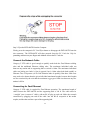
LED Indicators
The media coupler features three LED indicators:
•
10/100 Indicator: Steady green indicates Fast Ethernet selected. Dark indicates
10Mbps Ethernet selected.
•
Half /Full Indicator:
Steady green indicates Full-Duplex selected.
Dark indicates Half-Duplex selected.
•
Ln/Act Indicator:
Steady green indicates that there is good linkage to the network ("Linkage" state,
quiescent). Flashing green indicates that the DFE-680TX is transmitting or
receiving ("Activity" state). In 10Mbps mode, flashing will be regular and
periodic. In 100 Mbps mode, flashing may be irregular, with longer dark periods
during heavy traffic activity.
Summary of Features
Features of Model DFE-680TX 10/100 Ethernet PC Card:
•
100Mbps and 10Mbps data rates in compliance with IEEE 802.3
•
Ethernet standards 100Base-TX and 10Base-T
•
Complies with PCMCIA V2.x, JEIDA V4.x, and 32-Bit
•
CardBus Standards
•
CardBus standard 68-pin front-end connector
•
15-pin back-end connector for media coupler
•
Full-Duplex capable in 10Mbps and 100Mbps modes.
•
Autonegotiation per IEEE 802.3u specification
•
No manual setup switches –– fully automatic configuration
•
Power consumption 2 watts (max.)
4
•
Laser-welded stainless steel case
•
RJ-45 connector with auto-detection of network speed
•
Software support:
Diagnostic Program
NetWare DOS ODI
NetWare Lite
Personal NetWare
Windows 95 OSR2
Windows NT 3.51
Windows NT 4.0
Packet Driver for NCSA
Packet Driver for FTP PC/TCP
Packet Driver for IPX
Packet Driver for Winsock
Windows 98
Windows 98SE
Windows ME
Windows 2000
5
Hardware Installation
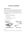
Unpack and Inspect
NOTE: Under ordinary circumstances, the DFE-680TX will not be affected by static
charge as may be received through your body during handling of the unit. In special
circum-stances where you may carry an extraordinarily high static charge, it is good
practice to reduce the charge by touching a ground before handling the DFE-680TX.
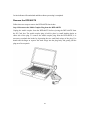
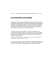
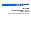
Open the shipping carton and carefully remove all items. In addition to this User's Guide,
ascertain that you have:
•
One DFE-680TX 10/100 Ethernet PC Card
•
One plastic storage bag for the DFE-680TX
•
One media coupler
•
One D-Link DFE-680TX Software CD-ROM
•
One Quick Installation Guide
Figure 1
In the event that any item is missing, or if you find any mismatch or damage, promptly
6
contact your dealer for an exchange.
Follow these four steps to install the DFE-680TX:
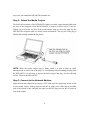
Step 1: Insert the DFE-680TX
Under the PC Card standard and the corresponding Japanese JEIDA standard, PC Cards
may safely be "hot swapped" –– it is not necessary to switch the computer's power off
before installing or removing the DFE-680TX, or any other PC Card.
Find/select an open Type II or Type III PC Card slot on your notebook computer's side or
rear panel. Hold the DFE-680TX with the colorful D-Link splash label upward. Notice
that the splash label features a yellow triangle or "arrow," which points to the front end of
the PC Card. Insert the front end of the PC Card into the CardBus slot, and slide the PC
Card all the way into the slot until it reaches a firm stop.
NOTE: Many notebook PCs feature a stacked pair of PC Card slots, logically (but not
physically) designated as Slot 1 and Slot 2.
It is most usual for the lower one of the two slots in the stack to be designated Slot 1, but
there are exceptions. In the subsequent procedure for DFE-680TX software installation, it
might be useful for you to know whether your DFE-680TX is installed in Slot 1 or Slot 2.
Under Windows 95, you can check by opening the Control Panel / PC Card display.
Under DOS it is also possible to make a software check, but it is more difficult. If it
develops that you need to make a trial-and-error determination or correction, then it is
7
easy to do: just reinstall the DFE-680TX in another slot.
Step 2: Attach the Media Coupler
The back-end receptacle of the DFE-680TX remains accessible (approximately flush with
the case of the computer) when the DFE-680TX is properly seated in its PC Card slot.
Taking care to keep the top side of the media coupler plug up, insert the plug into the
DFE-680TX's receptacle until it is firmly seated and latched. (The top side of the plug is
labeled with a triangle molded into the plastic.)
NOTE: When the media coupler plug is firmly seated, it is held in place by small
latching hooks at either side of the plug. To avoid damage when detaching the plug from
the DFE-680TX, it is necessary to depress the latch wings of the plug. See the following
section, " Remove the DFE-680TX."
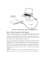
Step 3: Connect to the Network Medium
Make the network connection by running a UTP cable from the supporting switch or hub
to your media coupler. Simply plug one end (RJ-45 plug) of the cable into an available
port of the switch or hub, and plug the other end (RJ-45 plug) into the RJ-45 socket of
your media coupler.
8
Step 4: Confirm Connection (Ln/Act Indicator)
When the notebook computer's power is ON, the DFE-680TX is firmly seated in the slot
connector, the media adapter plug is firmly engaged (and latched) in the back-end
receptacle of the DFE-680TX, the media adapter has a good cable connection to the
supporting hub, and the supporting hub is power on and functioning properly, then the
media coupler’s Ln/Act LED glows steady green ("Linkage" state).
If the Ln/Act LED remains dark without apparent cause, then the most likely fault is poor
engagement of the 68-pin front -end plug. Review the following section titled "Remove
the DFE-680TX," then remove the DFE-680TX from its slot. Repeat the procedures of
the above Step 1, "Insert the DFE-680TX," taking care to ensure that the DFE-680TX is
right side up and front-end first, and that it seats firmly in a suitable PC Card slot of your
notebook. Repeat the procedures of Steps 2 and 3 as necessary get the Ln/Act LED
confirmation.
NOTE: You might need to wait a few seconds following notebook power up, or
following insertion of a PC Card, for the software processing to be completed. The
9
Ln/Act indicator will remain dark until the software processing is completed.
Remove the DFE-680TX
Follow these two steps to remove the DFE-680TX from its slot:
Step 1: Disconnect the Media Coupler Plug from the DFE-680TX
Unplug the media coupler from the DFE-680TX before ejecting the DFE-680TX from
the PC Card slot. The media coupler plug is held in place by small latching hooks at
either side of the plug. To remove the media coupler plug from the DFE-680TX, it is
necessary to unlatch the hooks by depressing the two small latch wings of the plug. Use
thumb and forefinger to squeeze the latch wings into the plug body and gently pull the
plug out of its receptacle.
10
Step 2: Eject the DFE-680TX from the Computer
Firmly press the computer's PC Card Eject button to disengage the DFE-680TX from the
slot connector. The DFE-680TX will then protrude from the PC Card slot. Grip its
protruding end between your fingers and withdraw it from the PC Card slot.
Connect the Network Cable
Category 5 UTP cable is good enough to qualify under both the Fast Ethernet cabling
rules and the traditional Ethernet cabling rules. The maximum individual cable run
between any station and its supporting hub or switch is 100m. The maximum individual
cable run joining two hubs is 10m in general, but is 100m when both hubs qualify as
Ethernet Class 2 Repeaters (all D- Link Ethernet hubs do qualify). But these cable runs
may need to be shorter than the given individual maximum lengths, because their lengths
are also restricted by the rule that the maximum aggregated cable run between any two
stations is 205m.
Connecting for Fast Ethernet
Category 5 UTP cable is required for Fast Ethernet operation. The maximum length of
cable between the DFE-680TX and the supporting hub is 300 ft. The cable must be
“ straight” (not a“crossover” cable), with an RJ-45 plug at each end. Make the network
connection by plugging one end of the cable into the RJ-45 receptacle of the media
coupler, and the other end into a port of the supporting hub.
11
Connecting for 10Mbps Ethernet
Category 3, Category 4, and Category 5 UTP cable, as well as EIA/TIA - 568 100-ohm
STP cable, all qualify under traditional Ethernet cabling rules. The maximum cable run
between the DFE-680TX and the supporting hub is 300 ft. The cable must be “straight”
(not a “ crossover” cable) with RJ-45 plug at each end. Make the network connection by
plugging one end of the cable into the RJ-45 receptacle of the media coupler, and the
other end into a port of the supporting hub.
12
Software Installation
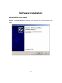
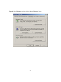
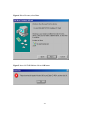
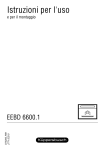
Windows2000 driver install
Figure1- Insert DFE-680TX into notebook, new hardware device should prompt. Select
Next.
13
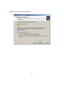
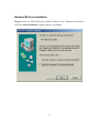
Figure2- Select Next to continue installation.
14
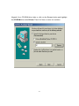
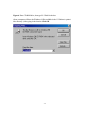
Figure3- Ensure that the Specify location box is checked and click Next
15
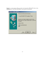
Figure4- Click Next to continue
16
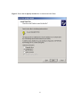
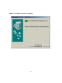
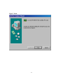
Figure5- The Digital Signature Not Found window appears. Click Yes to continue.
17
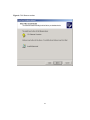
Figure6- Click Finish to complete the DFE-680TX Ethernet Card installation.
18
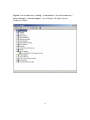
Device Manager for proper installation for Win2000
Figure7- Click the Start button > Settings > Control Panel >Then Double Click the
System icon and the Systems Properties should appear.
19
Figure8- Select Hardware and then click the Device Manager button
20
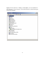
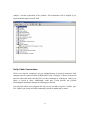
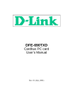
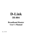
Figure9- The Device Manager menu. Double click on the Network Adapters and the
D-Link DFE-680 CardBus should appear showing proper installation.
21
Windows ME driver installation
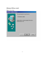
Figure1- Insert the DFE-680TX into available PCMCIA slot. Windows should detect
Card. The Add New Hardware windows appears, select Next
22
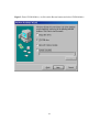
Figure2- Enter CD-ROM drive letter or click on the Browse button and highlight
the CD-ROM drive under Drivers. Then Click Next to continue the installation.
23
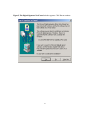
Figure3- A screen appears telling you that is has located the DFE-680TX driver in the
CD-ROM drive. Then click Next, Windows will copy files to the hard drive.
24
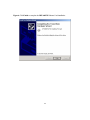
Figure4- Click Finish to complete driver installation.
25
Figure5- Click the start button > Settings > Control Panel > Click the System button >
Device Manager > Network Adapters. And D-Link DFE-680TX CardBus should appear
showing proper installation.
26
Windows 98 Driver install
Figure1- Select Next.
27
Figure2- Select Next
28
Figure3- Enter CD-ROM drive, or click on the Browse button and select CD-ROM drive.
29
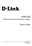
Figure4- Driver file name, select Next.
Figure5- Insert 98 CD-ROM then click on OK button.
30
Figure6- Enter CD-ROM drive, then type D:\ Win98 in the box.
(Some computers will have the Windows 98 files available in the C:\ Windows\ options\
cabs directory. )After typing in the location. Click OK.
31
Figure7- Finish
32
Figure8- Click the Start button > Setting > Control Panel > Click the System button >
Device Manager > Network Adapters. Device Manager will display of proper
installation of adapter.
33
Troubleshooting
Troubleshooting the Hardware Installation
If you experience any problems with the hardware installation, first ascertain that all
network cable connections are firm, that the proper grade of cable is used for the network
connection, and that the cable makeup is correct (straight –– without un-needed
crossovers in the connector wiring). Check that the supporting hub is power-on and
operating normally, and that the hub is properly qualified (under 10Base-T and/or
100Base-TX standards).
Verify Each Computers Identification
If more than one computer on your network has the same “Computer name,”
communications may be negatively affected. Also, each computer must have the same
“Workgroup” name to communicate properly.
Verify Network Adapter Installation
If your Network Adapter were not installed, including the Network System Software or
Device drivers, your network will not function properly. Use these steps to verify that
your Network Adapter are properly installed.
1. Double-Click the “System” icon in the Control Panel.
2. Click the “Device Manager” tab on top of the “System Properties” dialog box.
3. Double-Click “Network Adapters” if you do not see any items branching out. You
should see “D-Link DFE-680TX CardBus PC Card branching out after doubleClicking Network Adapters.”
If you do not see any items branching out after double-clicking “Network Adapters,”
your Network Adapter has not been properly installed. Start at the beginning of the guide
and follow these steps for this computer.
If you see symbols such as yellow exclamation point or red “X” over the icon adjacent to
“D-Link DFE-680TX/TXD CardBus PC Card,” your card is not installed properly or may
have a problem. Double-click the “ D-Link DFE-680TX/TXD CardBus PC Card
34
Adapter” read the explanation of the problem. This information will be helpful if you
require technical support from D-Link.
Verify Cable Connections
Check to see that the computer(s) you are troubleshooting are properly connected. Each
computer must be connected from its DFE-680TX with a Category 5 cables. Examine the
network cables and ensure that they have not been damaged by walking-on, rolling over
chairs, or closed in doors. Additionally, make note of and alleviate any possible
electromagnetic interference that may be effecting your network.
Your network cables can be plugged into any port on your hub except the “Uplink” port.
The “Uplink” port is only used when connecting your hub to another hub or switch.
35
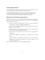
Understanding Indicators
Your DFE-680TX has indicators or lights that can give you information about your
network traffic and help you determine problems when troubleshooting.
Your DFE-680TX has two indicators label “ACT” and “LINK” on their back panels. A
steady green “LINK” light indicates a good connection with the hub. A flashing green
“ACT” light indicates that the Network Adapter is sending or receiving data.
Diagnostics and Checking Communications
Included on the CD-Rom is a “DFE-680TX PCMCIA Adapter Driver Program” is a
diagnostic program that will help you determine if any faults exist in your DFE-680TX
Network Adapters or connection.
1. Restart your computer in MS-DOS mode. (Click “Start”, then “”Shut Down…”,
and finally select “”Restart the computer in MS-DOS mode?”)
2. Insert the CD-Rom labeled “DFE-680TX PCMCIA Ethernet Adapter Driver
Program” into your CD-Rom D:\
3. Type D:\DIAG.EXE at the MS-DOS prompt and press “Enter” to start the D-Link
PCMCIA Fast Ethernet Adapter Diagnostic Program.
4. Read the follow the instructions on the screen (Press F1 key anytime for
additional help.)
5. “Adapter Basic Diagnostic” will determine if any problems exist with DFE680TX.
6. “Network Diagnostic” will determine if problems exist with your network or
connections. To use “Network Diagnostic”, please run program on both
computers in MS-DOS Mode.
If you encounter any problems, please contact D-Link technical support.
36
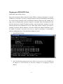
Pinging your DFE-680TX Card
Follow these steps to Ping a device:
Ping is the acronym for Packet Internet Groper (PING), a utility to determine if a specific
IP address is accessible. It works by sending a packet to the specified address and waiting
for a reply. Ping is primarily used to troubleshoot Internet connections. By sending out a
ping, you are verifying that a specific computer is available. Since all computers on the
network must have a unique IP address, getting a reply means that a computer is on the
network and that can communicate. If you cannot ping another computer, then there is
probably a problem with the hardware. Check the cabling and adapter installation. If you
are unable to network, even when you receive a reply to your ping, it is probably a
software configuration issue. Verify that all the settings are correct.
1. Start MS-DOS Prompt.
2. Type in following: ping:xxx.xxx.xx.xx, where xxx.xxx.xx.xx is the IP address to
be pinged (i.e. 192.152.81.85). In this case, computer A is pinging is own IP
address.
37
Specifications
Network Type:
Ethernet 100Base-TX
Ethernet IEEE 802.3u standard for 100Mbps baseband CSMA/CD local area network
Ethernet 10BASE-T
Ethernet IEEE 802.3 standard for 10Mbps baseband CSMA/CD
local area network
Jumperless Hardware
Autonegotiation functionality
Media interface: RJ-45
LAN Chip Set: ADMTEK AN985L
EMI Certifications:
FCC Class B
VCCI Class B
CE Certification
Host interface: CardBus
I/O base address assigned by Plug and Play system
Interrupt Number Assigned by Plug and Play system
Physical Dimensions: 85.6 × 54.0 × 3.0 mm
Environment:
Storage: -20° to 70°C, (-4° to 158° F)
Operating: 0° to 60° C, (32° to 140° F)
Humidity: 10% to 90% non-condensing
Power Consumption: 2.0W
PCB Construction: 2 layers
38
Device Drivers*
• Diagnostic Program
• NetWare Lite
• Personal NetWare
• NetWare DOS ODI
• Windows 95 OSR2
• Windows 98
• Windows 98 SE
• Windows ME
• Windows 2000
• Windows NT 3.51
• Windows NT 4.0
• Packet Driver for NCSA
• Packet Driver for IPX
• Packet Driver for Winsock
• Packet Driver for FTP PC/TCP
*Check http://www.dlink.com for newest
releases of drivers.
D-Link provides free technical support. North American customers can contact D-Link
technical support through our web site, e-mail, or by phone. North American technical
support is available Monday through Friday from 6:00 a.m. to 6:00 p.m. (PST).
Web: http://www.dlink.com/tech/
E-mail: [email protected]
Phone: 949-788-0805 (option #4)
39
FCC Certifications
This equipment has been tested and found to comply with the limits for a Class B digital
device, pursuant to Part 15 of the FCC Rules. These limits are designed to provide
reasonable protection against harmful interference in a residential installation. This
equipment generates, uses and can radiate radio frequency energy and, if not installed and
used in accordance with the instructions, may cause harmful interference to radio
communications. However, there is no guarantee that interference will not occur in a
particular installation. If this equipment does cause harmful interference to radio or
television reception, which can be determined by turning the equipment off and on, the
user is encouraged to try to correct the interference by one or more of the following
measures:
• Reorient or relocate the receiving antenna.
• Increase the separation between the equipment and receiver.
• Connect the equipment into an outlet on a circuit different from that to which the receiver is connected.
• Consult the dealer or an experienced radio/TV technician for help.
Shielded interface cables must be used in order to comply with emission limits.
You are cautioned that changes or modifications not expressly approved by the party
responsible for compliance could void your authority to operate the equipment.
This device complies with Part 15 of the FCC rules. Operation is subject to the following
two conditions: (1) This device may not cause harmful interference, and (2) This device
must accept any interference received, including interference that may cause undesired
operation.
CE Mark Warning
This is a Class B product. In a domestic environment, this product may cause
radio interference, in which case the user may be required to take adequate
measures.
i
VCCI Warning
ii
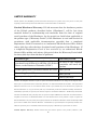
LIMITED WARRANTY
D-Link Systems, Inc.(“D-LINK”) provides this limited warranty for its product only to the person or entity who
originally purchased the product from D-Link or its authorized reseller or distributor.
Limited Hardware Warranty: D-Link warrants that the hardware portion
of the D-Link products described below (“Hardware”) will be free from
material defects in workmanship and materials from the date of original
retail purchase of the Hardware, for the period set forth below applicable to
the product type (“Warranty Period”) if the Hardware is used and serviced in
accordance with applicable documentation; provided that a completed
Registration Card is returned to an Authorized D-Link Service Office within
ninety (90) days after the date of original retail purchase of the Hardware. If
a completed Registration Card is not received by an authorized D-Link
Service Office within such ninety (90) period, then the Warranty Period shall
be ninety (90) days from the date of purchase.
Product Type
Product (excluding power supplies and fans), if
purchased and delivered in the fifty (50) United
States, or the District of Columbia (“USA”)
Warranty Period
Product purchased or delivered outside the USA
One (1) Year
Power Supplies and Fans
One (1) Year
Spare parts and spare kits
Ninety (90) days
As long as the original
purchaser still owns the
product
D-Link’s sole obligation shall be to repair or replace the defective Hardware at no charge to the original owner.
Such repair or replacement will be rendered by D-Link at an Authorized D-Link Service Office. The replacement
Hardware need not be new or of an identical make, model or part; D-Link may in its discretion may replace the
defective Hardware (or any part thereof) with any reconditioned product that D-Link reasonably determines is
substantially equivalent (or supe rior) in all material respects to the defective Hardware. The Warranty Period shall
extend for an additional ninety (90) days after any repaired or replaced Hardware is delivered. If a material defect is
incapable of correction, or if D-Link determines in its sole discretion that it is not practical to repair or replace the
defective Hardware, the price paid by the original purchaser for the defective Hardware will be refunded by D-Link
upon return to D-Link of the defective Hardware. All Hardware (or part thereof) that is replaced by D-Link, or for
which the purchase price is refunded, shall become the property of D-Link upon replacement or refund.
Limited Software Warranty: D-Link warrants that the software portion of the product (“Software”) will
iii
substantially conform to D-Link’s then current functional specifications for the Software, as set forth in the
applicable documentation, from the date of original delivery of the Software for a period of ninety (90) days
(“Warranty Period”), if the Software is properly installed on approved hardware and operated as contemplated in its
documentation. D-Link further warrants that, during the Warranty Period, the magnetic media on which D-Link
delivers the Software will be free of physical defects. D-Link’s sole obligation shall be to replace the non-conforming
Software (or defective media) with software that substantially conforms to D-Link’s functional specifications for the
Software. Except as otherwise agreed by D-Link in writing, the replacement Software is provided only to the
original licensee, and is subject to the terms and conditions of the license granted by D-Link for the Software. The
Warranty Period shall extend for an additional ninety (90) days after any replacement Software is delivered. If a
material non-conformance is incapable of correction, or if D-Link determines in its sole discretion that it is not
practical to replace the non-conforming Software, the price paid by the original licensee for the non-conforming
Software will be refunded by D-Link; provided that the non-conforming Software (and all copies thereof) is first
returned to D-Link. The license granted respecting any Software for which a refund is given automatically
terminates.
What You Must Do For Warranty Service:
Registration Card. The Registration Card provided at the back of this manual must be completed and returned to
an Authorized D-Link Service Office for each D-Link product within ninety (90) days after the product is purchased
and/or licensed. The addresses/telephone/f ax list of the nearest Authorized D-Link Service Office is provided in the
back of this manual. FAILURE TO PROPERLY COMPLETE AND TIMELY RETURN THE REGISTRATION
CARD MAY AFFECT THE WARRANTY FOR THIS PRODUCT.
Submitting A Claim. Any claim under this limite d warranty must be submitted in writing before the end of the
Warranty Period to an Authorized D-Link Service Office. The claim must include a written description of the
Hardware defect or Software nonconformance in sufficient detail to allow D-Link to confirm the same. The original
product owner must obtain a Return Material Authorization (RMA) number from the Authorized D-Link Service
Office and, if requested, provide written proof of purchase of the product (such as a copy of the dated purchase
invoice for the product) before the warranty service is provided. After an RMA number is issued, the defective
product must be packaged securely in the original or other suitable shipping package to ensure that it will not be
damaged in transit, and the RMA number must be prominently marked on the outside of the package. The
packaged product shall be insured and shipped to D-Link, 53 Discovery Drive, Irvine CA 92618, with all shipping
costs prepaid. D-Link may reject or return any product that is not packaged and shipped in strict compliance with
the foregoing requirements, or for which an RMA number is not visible from the outside of the package. The product
owner agrees to pay D-Link’s reasonable handling and return shipping charges for any product that is no t packaged
and shipped in accordance with the foregoing requirements, or that is determined by D-Link not to be defective or
iv
non-conforming.
What Is Not Covered:
This limited warranty provided by D-Link does not cover:
Products that have been subjected to abuse, accident, alteration, modification, tampering, negligence, misuse, faulty
installation, lack of reasonable care, repair or service in any way that is not contemplated in the documentation for
the product, or if the model or serial number has been altered, tampered with, defaced or removed;
Initial installation, installation and removal of the product for repair, and shipping costs;
Operational adjustments covered in the operating manual for the product, and normal maintenance;
Damage that occurs in shipment, due to act of God, failures due to power surge, and cosmetic damage; and
Any hardware, software, firmware or other products or services provided by anyone other than D-Link.
Disclaimer of Other Warranties: EXCEPT FOR THE LIMITED WARRANTY SPECIFIED HEREIN, THE
PRODUCT IS PROVIDED “AS-IS” WITHOUT ANY WARRANTY OF ANY KIND INCLUDING, WITHOUT
LIMITATION, ANY WARRANTY OF MERCHANTABILITY, FITNESS FOR A PARTICULAR PURPOSE AND
NON-INFRINGEMENT.
IF ANY IMPLIED WARRANTY CANNOT BE DISCLAIMED IN ANY TERRITORY
WHERE A PRODUCT IS SOLD, THE DURATION OF SUCH IMPLIED WARRANTY SHALL BE LIMITED TO
NINETY (90) DAYS. EXCEPT AS EXPRESSLY COVERED UNDER THE LIMITED WARRANTY PROVIDED
HEREIN, THE ENTIRE RISK AS TO THE QUALITY, SELECTION AND PERFORMANCE OF THE PRODUCT IS
WITH THE PURCHASER OF THE PRODUCT.
Limitation of Liability: TO THE MAXIMUM EXTENT PERMITTED BY LAW, D-LINK IS NOT LIABLE UNDER
ANY CONTRACT, NEGLIGENCE, STRICT LIABILITY OR OTHER LEGAL OR EQUITABLE THEORY FOR ANY
LOSS OF USE OF THE PRODUCT, INCONVENIENCE OR DAMAGES OF ANY CHARACTER, WHETHER DIRECT,
SPECIAL, INCIDENTAL OR CONSEQUENTIAL (INCLUDING, BUT NOT LIMITED TO, DAMAGES FOR LOSS
OF GOODWILL, WORK STOPPAGE, COMPUTER FAILURE OR MALFUNCTION, LOSS OF INFORMATION OR
DATA CONTAINED IN, STORED ON, OR INTEGRATED WITH ANY PRODUCT RETURNED TO D-LINK FOR
WARRANTY SERVICE) RESULTING FROM THE USE OF THE PRODUCT, RELATING TO WARRANTY
SERVICE, OR ARISING OUT OF ANY BREACH OF THIS LIMITED WARRANTY, EVEN IF D-LINK HAS BEEN
ADVISED OF THE POSSIBILITY OF SUCH DAMAGES. THE SOLE REMEDY FOR A BREACH OF THE
FOREGOING LIMITED WARRANTY IS REPAIR, REPLACEMENT OR REFUND OF THE DEFECTIVE OR NONCONFORMING PRODUCT.
GOVERNING LAW: This Limited Warranty shall be governed by the laws of the state of California.
v
Some states do not allow exclusion or limitation of incidental or consequential damages, or limitations on how long an
implied warranty lasts, so the foregoing limitations and exclusions may not apply. This limited warranty provides
specific legal rights and the product owner may also have other rights which vary from state to state.
vi
Offices
AUSTRALIA D-LINK AUSTRALASIA
Unit 16, 390 Eastern Valley Way, Roseville, NSW 2069, Australia
TEL: 61-2-9417-7100 FAX: 61-2-9417 -1077
TOLL FREE: 1800-177-100 (Australia), 0800-900900 (New Zealand)
URL: www.dlink.com.au E-MAIL: [email protected], [email protected]
CANADA
D-LINK CANADA
2180 Winston Park Drive, Oakville, Ontario L6H 5W1 Canada
TEL: 1-905-829-5033 FAX: 1-905-829-5095 BBS: 1 -965-279-8732 FREE CALL: 1-800-354-6522
URL: www.dlink.ca E-MAIL: [email protected]
CHILE
D-LINK SOUTH AMERICA
Isidora Goyenechea #2934 of.702, Las Condes, Santiago, Chile
TEL:
56-2-232-3185 FAX: 56-2-2320923 URL: www.dlink.cl
CHINA
D-LINK CHINA
2F., Sigma Building, 49 Zhichun Road, Haidian District, 100080 Beijing, China
TEL: 86-10-88097777 FAX: 86-10-88096789
URL: www.dlink.com.cn
DENMARK D-LINK DENMARK
Naverland 2, DK-2600 Glostrup, Copenhagen, Denmark
TEL:45-43-969040 FAX:45-43-424347 URL: www.dlink.dk
E-MAIL: [email protected]
EGYPT
D-LINK MIDDLE EAST
7 Assem Ebn Sabet Street, Heliopolis Cairo, Egypt
TEL: 202-2456176 FAX: 202-2456192 URL: www.dlink-me.com
E-MAIL: [email protected]
FRANCE
D-LINK FRANCE
Le Florilege #2, Allee de la Fresnerie
78330 Fontenay Le Fleury France
TEL: 33-1-30238688 FAX: 33-1-3023-8689 URL: www.dlink-france.fr
E-MAIL: [email protected]
GERMANY
D-LINK Central Europe/D-Link Deutschland GmbH
Schwalbacher Stra_e74
65760 Eschborn, Germany
TEL: 49-6196-77990 FAX: 49-6196-7799300
URL: www.dlink.de BBS: 49-(0)6192-971199 (Analog) 49-(0)6192-971198 (ISDN)
INFO LINE: 00800-7250-0000 (toll free) HELP LINE: 00800-7250-4000 (toll free)
REPAIR LINE: 00800-7250-8000
INDIA
D-LINK INDIA
Plot No.5, Kurla-Bandra Complex Road,
Off Cst Road, Santacruz (E), Bombay - 400 098 India
TEL: 91-22-652-6696 FAX: 91-22-652-8914 URL: www.dlink-india.com
E-MAIL: [email protected]
ITALY
D-LINK MEDITERANEO SRL
Via Nino Bonnet No. 6/b, 20154 Milano, Italy
TEL: 39-02-2900-0676 FAX: 39-02-2900-1723 URL: www.dlink.it
E-MAIL: [email protected]
JAPAN
D-LINK JAPAN
10F, 8-8-15 Nishi-Gotanda, Shinagawa-ku, Tokyo 141 Japan
TEL: 81-3-5434-9678 FAX: 81-3-5434 -9868 URL: www.d-link.co.jp
RUSSIA
D-LINK RUSSIA
Michurinski Prospekt 49, 117607 Moscow, Russia
TEL: 7-095-737-3389, 7-095-737-3492 FAX: 7-095-737-3390
SINGAPORE D-LINK INTERNATIONAL
1 International Business Park, #03-12 The Synergy, Singapore 609917
TEL: 65-774-6233 FAX: 65-774-6322
URL: www.dlink-intl.com E-MAIL: [email protected]
S. AFRICA
D-LINK SOUTH AFRICA
Unit 2, Parkside 86 Oak Avenue
Highveld Technopark Centurion, Gauteng, Republic of South Africa
TEL: 27(0)126652165 FAX: 27(0)126652186
SWEDEN
D-LINK SWEDEN
P.O. Box 15036, S -167 15 Bromma Sweden
TEL: 46-(0)8564-61900 FAX: 46-(0)8564-61901 E-MAIL: [email protected]
URL: www.dlink.se
TAIWAN
D-LINK TAIWAN
2F, No. 119 Pao-Chung Road, Hsin-Tien, Taipei, Taiwan,
TEL: 886-2-2910-2626 FAX: 886-2-2910-1515 URL: www.dlinktw.com.tw
U.K.
D-LINK EUROPE
4th Floor, Merit House, Edgware Road, Colindale, London, NW9 5AB, U.K.
TEL: 44-20-8731-5555 FAX: 44-20-8731-5511
URL: www.dlink.co.uk E-MAIL: [email protected]
U.S.A.
D-LINK U.S.A.
53 Discovery Drive, Irvine, CA 92618 USA
TEL: 1-949-788-0805 FAX: 1-949-753-7033 INFO LINE: 1-800-326-1688
BBS: 1-949-455-1779, 1-949-455-9616
URL: www.dlink.com E-MAIL: [email protected], [email protected]