1
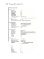
CodeWriter 5106
Technical Reference
PART NO. 108741 Rev. A
AMT Datasouth Corp.
Corporate Headquarters
4765 Calle Quetzal
Camarillo, CA 93012
(805) 388-5799 PH
(805) 484-5282 FX
Charlotte Operation
4216 Stuart Andrew Blvd.
Charlotte, NC 28217
(704) 523-8500 PH
(704) 525 6104 FX
www.amtdatasouth.com
AMT Datasouth International
Unit B, Pinnacle 15
Gowerton Rd, Brackmills
Northampton, NN4 7BW
England
+44 1604 763394 PH
+44 1604 760661 FX
AMT Datasouth CodeWriter 5106 Disclaimer of
Warranties
IMPORTANT!
READ THIS FIRST; IT LIMITS OUR LIABILITY
SOFTWARE
All software is licensed “as is” without warranty of any kind, either expressed or implied,
including but not limited to the implied warranties of merchantability and fitness for a
particular purpose. AMT Datasouth Corp. and it’s authorized sales agent have no
liability, loss, or damage caused, or alleged to have been caused directly or indirectly by
the software system (hardware, software, User’s Guide, User’s Manual, and labels), nor
for indirect, special, or consequential damages. In no event will AMT Datasouth Corp.
be liable to you for any damages, including any lost profits, savings, or other incidental or
consequential damages arising out of the use or inability to use any program produced by
AMT Datasouth Corp. or any authorized dealer advised of the possibility of such
damages occurring. No person has the authority to modify such limitations, unless
obtained in writing and signed by a corporate officer at AMT Datasouth Corp.
Acceptance of software is conditional on the acceptance of this disclaimer. Use of the
hardware/software constitutes acceptance of this disclaimer.
EXTENDED SOFTWARE SUPPORT
AMT Datasouth Corp. provides telephone support and maintenance following delivery
of your software/hardware system. Check with AMT Datasouth Corp. for details and
current pricing on extended maintenance support.
HARDWARE
Hardware provided with your system is warranted to be free from defects in
workmanship and performance by the respective manufacturers. Refer to the AMT
Datasouth Service Policy and Pricing Handbook for warranty information. Call customer
support at (800) 476-2450 for return authorization. CodeWriter is a trademark of AMT
Datasouth Corp. All other brand and product names are trademarks or registered
trademarks of their respective companies.
LABELS, TAGS AND RIBBONS
Only previously authorized label and ribbon material may be used in this printer. Due to
variations in label and ribbon quality, use of unauthorized material may void the
warranty. Check with your AMT Datasouth Dealer for a list of authorized suppliers. In
the event you require a special material for your labels, tags or ribbons you may send
samples to the manufacturer for authorization.
COPYRIGHT NOTICE
This guide is copyrighted. All rights reserved. This guide may not, in whole or part, be
reproduced, translated, stored in a retrieval system or transmitted in any forms or by any
means, electronic, mechanical, photographic, or otherwise, without the prior written
consent of AMT Datasouth Corp.
The following expressions are used to explain keyboard
operations:
•
Depress [SHIFT] means: depress the [SHIFT] key.
•
Depress [1] [4] [1] or [1, 4, 1] means: depress the [1], [4], then the [1] keys.
•
Depress [SHIFT] + [1, 4, 1] or [R + 1, 4, 1] means: while depressing the [SHIFT]
key, depress the [1], [4], then the [1] keys.
The following abbreviations are used throughout this
documentation:
•
mm = millimeter
•
cm = centimeter
•
um = micrometer
•
KB = kilobyte
•
MB = megabyte
•
ns = nanoseconds
•
A = ampere
•
MHz = megahertz
•
mV = millivolt
•
Vac = voltage alternating
current
Vdc = voltage direct current
•
h/s screw = hexagon socket
screw
•
Table of Contents
1.0
1.1
1.2
1.3
2.0
2.1
2.2
2.3
2.4
3.0
4.0
4.1
4.2
4.3
5.0
6.0
6.1
6.2
7.0
8.0
9.0
10.0
11.0
12.0
13.0
GENERAL INFORMATION........................................................................................................................... 1
Features............................................................................................................................................................ 1
5106 Overall Dimensions............................................................................................................................. 2
Ribbon Specifications ................................................................................................................................... 2
INITIAL SETUP................................................................................................................................................. 3
Assembly and Setup Procedure ................................................................................................................... 3
Selection of Media Output Mode................................................................................................................ 3
Parameter Setting Mode................................................................................................................................ 4
Parameter Tree Version 1.90........................................................................................................................ 5
LOADING INK RIBBON AND LABEL ROLL.......................................................................................... 6
ADJUSTMENTS................................................................................................................................................ 8
Thermal Head Replacement ......................................................................................................................... 8
Changing the Direction of the Take-up Roller.......................................................................................... 9
Thermal Head Positioning .......................................................................................................................... 10
MECHANICAL ADJUSTMENTS TO THE THERMAL HEAD.......................................................... 11
RIBBON............................................................................................................................................................. 17
Ribbon Adjustment...................................................................................................................................... 17
Running Condition....................................................................................................................................... 19
SENSORS.......................................................................................................................................................... 21
SENSITIVITY ADJUSTMENT .................................................................................................................... 22
ELECTRICAL CIRCUITRY.......................................................................................................................... 24
EXTERNAL CONNECTOR AND PIN ASSIGNMENTS....................................................................... 25
VOLTAGE CHECK AND ADJUSTMENT............................................................................................... 26
MAIN PCB BOARD........................................................................................................................................ 27
TAKE-UP MOTOR CONNECTORS........................................................................................................... 28
Table of Figures
Figure 1. Overall Dimensions........................................................................................................................................ 2
Figure 2. Ribbon Dimensions........................................................................................................................................ 2
Figure 3: Loading Ribbon and Label Roll................................................................................................................... 6
Figure 4. Thermal Head Replacement.......................................................................................................................... 8
Figure 5. Thermal Head Block..................................................................................................................................... 10
Figure 6. Mechanical Adjustment............................................................................................................................... 11
Figure 7. Hinge of Thermal Head Lever.................................................................................................................... 12
Figure 8. Thermal Head Alignment............................................................................................................................ 13
Figure 9. Thermal Head Positioning........................................................................................................................... 14
Figure 10. Head Positioning......................................................................................................................................... 15
Figure 11. Incline Checking of the Thermal Head................................................................................................... 16
Figure 12. Ribbon Running Condition....................................................................................................................... 18
Figure 13. Wrinkle On Ribbon.................................................................................................................................... 19
Figure 14. Ribbon Application Adjustment.............................................................................................................. 20
Figure 15. Location of Sensors and Switch............................................................................................................... 21
1.0 GENERAL INFORMATION
The 5106 is a general thermal printer which offers universal printing, including various
types of barcodes. High speed and high dot density print is available which allows you to
create any label format desired through computer software generated code.
1.1
Features
•
Both On-line/Off-line operation modes available
•
Thermal direct and thermal transfer printing systems are adopted.
•
Extremely high dot density – 203 dots/inch or 8 dots/mm.
•
High speed printing – 6.00 inches/sec or 150 mm/sec.
•
Most industry standard symbologies supported.
•
Built-in internal and external rewind mechanism.
•
Wide print width – 5.04 inches or 128 mm
1
1.2
5106 Overall Dimensions
•
Length: 17.3 inches/440 millimeters
•
Extended Rewind: (On center from front) 4.2 inches/107 millimeters
•
Height: 12.6 inches/320 millimeters
•
Width: 10.7 inches/273 millimeters
Figure 1. Overall Dimensions
1.3
Ribbon Specifications
•
Length: 984 feet/300 meters
•
Ribbon Leader (Clear): 12 inches/300 millimeters
•
Ribbon Trailer (Mirror coating): 6 inches/150 millimeters
•
Ink Side: Outside
Figure 2. Ribbon Dimensions
2
2.0 INITIAL SETUP
2.1
Assembly and Setup Procedure
The 5106 printer provides various output modes which will correspond to the various
customer requirements. Assemble and setup the printer according to the customer
application.
2.2
Selection of Media Output Mode
Output Mode under printer parameters provides the selection. Refer to the next section
when choosing parameter settings.
Output Mode
Non-spooled
Function
The label is issued with the liner.
(The printer does not rewind the
label and liner). Attaching the
Tear Bar instead of the
Presentation Sensor, the label
and liner can then be torn off
together (manually)
Spooled
Presentation
Optional Cutter
The label is issued with liner, and
the printer rewinds both the
issued label and liner on the
Take-Up Roller (as an external
rewinder).
The labels are issued with liner
and peeled off at the dispenser
and present Label Holder. The
printer rewinds only the liner,
inside the printer.
Remark
Remove label Presentation
Sensor and then attach the
Tear Bar.
Position the Take-Up
Roller on the outside of the
printer (as an external
rewinder).
Set the Take-Up Roller on
the inside of the printer.
Optional cutter mechanism
is required.
The labels are issued with liner
and separated in the specified
timing by the Optional Cutter.
3
2.3
Parameter Setting Mode
To enter the parameter setting mode, perform the following operations. Refer to the
parameter tree, page 8 for 1.90 settings.
•
•
•
Press [ON LINE] to toggle to “Off-line” mode if the printer is On-line.
Press [MODE/MENU] to enter the parameter setting mode.
The following keys are provided for the parameter setting operations.
[MODE/MENU]
§ Enters parameter setting mode.
§ Returns to the branch menu from data setting mode.
§ Returns to “Off-line” mode after selection of the following:
[ENTER]
to save as new defaults
[ENTER]
to exit without saving
[ENTER]
to restore factory default
[ENTER]
to restore previous default
[ / ]
§
Moves among the top of the branch mode when the display shows branch
mode titles listed here.
- Print parameters
- Label parameters
- Time set
§
- I/O configuration
- System parameters
Selects data in each parameter when the display shows the parameter
name.
[é/ê]
§
Moves among the parameters in each branch mode.
[n]
§
Numeric keys have two functions : one numeric in the first input activates
key entry for data change, two or three digit numerics following previous
input is data to be changed.
[ENTER/PRINT]
§
§
§
•
4
Pushed input data into the buffer after this key is depressed to select or
input data. At this moment, this key just lets the printer know which data
is input and the printer does not store new data yet.
Decides on the selection when the display asks next action.
Stores data into the memory when this key is depressed following to data
input.
Date and time should be set ON.
2.4
Parameter Tree Version 1.90
5
3.0 LOADING INK RIBBON AND LABEL ROLL
Note:
Incorrect loading of ink ribbon or label roll may result in wrinkling of ribbon, feeding fault of
labels or printing fault.
Figure 3: Loading Ribbon and Label Roll
1. Open right side cover to access label roll compartment.
2. Push thermal head lever back to release thermal head block.
3. Place in ribbon roll on the ribbon supply shaft and the take-up core to the ribbon
rewind axis. If the core does not fit properly, adjust the slant of the Spring EC as
follows:
•
•
Core too tight - remove, then flatten the spring.
Core too loose – remove, then angle the spring.
4. Peel off the leader tape from the ribbon roll and feed the leader tape under the thermal
head block, then attach the ribbon onto the take-up core. (See Figure 3)
Note:
Make sure to pass the ink ribbon between the ribbon sensor and reflective plate. If you
do not, it may result in a ‘Ribbon Out’ error or a break in the ribbon.
5. Adjust the position of the label roll holder. If a wider label roll is loaded, add one
more holder to the label roll support.
6
6. Place the label roll on the label roll support and push it into the label roll
compartment until the roll touches the frame.
7.
•
If outside winding label roll is used:
Place the roll so that it rotates counterclockwise when pulling the leading edge
of the liner.
•
If inside winding label roll is used:
Place the roll so that it rotates clockwise when pulling the leading edge of liner.
Pull the leading edge of the liner under the white shaft, paper guide and thermal head
block.
8. Set the leading edge of the liner in accordance with Media output mode. For
example: Wind the liner onto the take-up roller as used in the presentation mode.
9. Place (label) roll holder onto label support. Leave a slight gap between media roll
holder and media roll (about 1 mm).
10. Pull the thermal head lever forward to latch the thermal head block. In the “Off-line
mode”, press [FEED] a few times in order to remove wrinkles from the ribbon and
align label leading edge to thermal head by media gap sensor.
Note:
Make sure to latch thermal head block by thermal head lever. If not, it may result in ‘Head not
latched’ error.
If a mechanical adjustment to the thermal head is needed, use the following methods to make
adjustments.
If you are using Fan Fold Labels:
•
Load the labels through either position as indicated in Figure 3.
•
Follow the steps you would normally use to load a label roll (over the roll stock
and into the paper guide).
7
4.0 ADJUSTMENTS
4.1
Thermal Head Replacement
Note:
Make sure to power off the printer prior to the replacement of the thermal head. There is
no need to disassemble the thermal head block or to loosen the four h/s screws when
replacing the thermal head.
1.
Push back the thermal head lever in order to release the thermal head block from
the platen roller.
2.
Loosen (but do not remove) the two hexagon bolts on the thermal head block
until the thermal head can be removed.
3.
Disconnect cable, then pull out the thermal head.
4.
Replace the thermal head and connect the cable to the replacement head.
Figure 4. Thermal Head Replacement
5.
Push both wires and thermal head back to original position on bracket EA.
Bracket EA has two locations on its underside to locate the head position
correctly (see Figure 9, page 17).
6.
While holding thermal head at its original position, tighten two hexagon bolts
temporarily. Then fix thermal head to bracket EA.
Note:
Incorrect position of thermal head on bracket EA will cause the ribbon to wrinkle or
cause uneven contrast when printing on media (labels).
8
7.
Confirm the original position of the thermal head again. Then tighten two
hexagon bolts to fix thermal head to bracket EA.
Note:
Over-tightening hexagon bolt may cause the screw thread to break.
8.
Clean the elements of the thermal head by using a soft cloth with isopropyl
alcohol. Test print a label. If the printing result is uneven or contrast is
unacceptable, check the original fixing position of the thermal head at first and
adjust the thermal head position as necessary.
4.2
Changing the Direction of the Take-up Roller
1.
Power off the printer.
2.
Fully extend the take-up roller.
3.
Remove the take-up roller motor cover.
4.
Switch the locations of the red and white wires on the motor side of the connector.
5.
Reinstall the cover.
9
4.3
Thermal Head Positioning
If you have replaced the thermal head, positioning should be checked. Verify the ribbon
running condition as well.
Note:
Make sure of the following prior to the adjustment:
•
Power off the printer
•
Use full width media (labels) 5.2 in./132 mm) when checking.
•
Rotate the head pressure screw clockwise completely.
Figure 5. Thermal Head Block
10
5.0 MECHANICAL ADJUSTMENTS TO THE THERMAL
HEAD
If you have encountered print quality problems on the left or right side of your labels, the
following adjustments may help.
1.
Have both a phillips and a slotted screwdriver available. The phillips screwdriver
is used for loosening and tightening screws while the slotted screwdriver is used
to adjust the position of moveable parts.
2.
Loosen phillips screw(s) slightly to allow movement which holds the adjustable
part.
3.
Use the slotted screwdriver as a wedge or fulcrum to turn or push lightly on the
part you are attempting to adjust.
4.
Once you have made the adjustment, hold the position of the adjustment while
tightening the phillips screw(s).
Figure 6. Mechanical Adjustment
11
If after the above adjustments have been made, you find yourself continuing to
experience problems, try the following:
1.
Push back the thermal head lever in order to release the thermal head block from
the platen roller.
2.
Loose the two phillips screws which fix Bracket EA, which supports the thermal
head, to Bracket AA.
3.
Set Bracket EA to the front edge of Bracket AA. Tighten the two phillips screws
temporarily. Pull up the thermal head lever.
4.
Check for a .787” distance from the upper surface of the aluminum plate of the
thermal head to the upper surface of Bracket AA at the right side of the thermal
head block. If it is not .787”, continue to the next step. If the distance is .787”,
go to Step 8.
5.
Push down the thermal head lever again. Loosen the left screw as shown in
Figure 7.
Figure 7. Hinge of Thermal Head Lever
6.
Move up the bracket on the thermal head lever hinge to measure .20mm. Tighten
the h/s screw.
7.
Pull up the thermal head lever. Check for a .20mm distance from the upper
surface of the aluminum plate on the thermal head to the upper surface of Bracket
AA. If it measures 20mm, go to the next step.
12
8.
Check to see if the bottom edge of the ribbon applicator aligns to the bottom edge
of the thermal head. (See Figure 8) If not, adjust the alignment following Steps 5
through 7. The right h/s screw is used for adjustments.
Figure 8. Thermal Head Alignment
9.
After adjustments have been made, check to see if the elements of the thermal
head are clean. If they are not, clean them with a soft cloth dampened with
isopropyl alcohol.
10.
Load ribbon and media (labels) into the printer. Power the printer on. Feed the
media (labels) a few times in order to align media (labels) and remove any
wrinkles from the ribbon.
11.
Check to make sure all the parameters are set to the factory defaults. Set the
parameter as indicated below:
•
•
•
•
12.
Print Speed: 85
Print Contrast: Less than 30% as weak as printing result can be readable.
Label Width: 5.03 in./128 mm
Label Length Intervening Label Gap: Varies according to the label stock
being used.
Issue a few labels. Then perform test printing under the following conditions:
•
•
•
Issued under normal conditions = Result 1
Issued while pushing the right hand side of the thermal head block down
slightly with your finger = Result 2
Issued while lifting the right hand side of the thermal head block up
slightly with your finger = Result 3
13
NOTE:
Too much lifting up of the thermal head will result in too light (weak) of a contrast in
printing. Adjusting the head pressure thumb screw will have a direct effect on the
contrast, ribbon feeding, and form feeding.
13.
If the right part of the contrast of Result 3 is better than others, move Bracket EA
to the rear slightly by loosening the one phillips screw. When the right part of the
contrast of Result 2 is better than others, move Bracket EA to the front slightly by
loosening two phillips screws. If the ribbon applicator interferes with the thermal
head, move it forward
Figure 9. Thermal Head Positioning
NOTE:
The thermal head and Bracket EA are fixed so that the parts rotate around the shaft as
indicated in Figure 10. Therefore, when you push the thermal head block down, the
relative position between the heat line of the thermal head and the center of the platen
roller becomes narrower. This is similar to moving the thermal head toward the front.
When lifting the thermal head block up, the relative position between the heat line of the
thermal head and the center of the platen roller becomes wider. This is similar to moving
the thermal head to the rear.
14
Figure 10. Head Positioning
14. Repeat Steps 10 through 13 as required until the right part of the contrast of Result 1
is better than Result 2 or 3.
15. Perform test printing as detailed in Step 12 for the left part contrast. If needed, use a
small slotted screwdriver rod to push down or lift up the left hand side of the thermal
head block to achieve the desired results.
16. When the test printing on both sides is acceptable, you need to check for incline on
the printing result. Fold the media (label) vertically. If the difference of printing
between the right side and the left side of the label is more than .02 in./0.5 mm, you
will need to adjust the position of Bracket EA accordingly. See Figure 11.
15
Figure 11. Incline Checking of the Thermal Head
17.
16
Set all parameters to factory default values. Then perform the test printing again.
The printing result should be excellent.
6.0 RIBBON
When thermal transfer is selected as print media type, the following adjustment should be
made in accordance with ribbon running condition. If you have repositioned the thermal
head, it is highly recommended to adjust the ribbon.
6.1
Ribbon Adjustment
To understand ribbon adjustment better, refer to the following explanation.
Ribbon running condition is directly related to the condition of the following
components:
•
Ribbon supply shaft with friction brake. Ribbon roll is loaded to this shaft.
The friction brake is provided to eliminate looseness from ribbon.
•
Leading shaft to change ribbon running direction.
•
Heat lines of thermal head and platen roller.
•
Bottom front edge of thermal head.
•
Bottom edge and surface of ribbon applicator to change ribbon running
direction.
•
Ribbon take-up shaft. Take-up core is set on this shaft in order to wind
waste ribbon. Take-up motor powers this shaft.
From the above ribbon components, the ribbon on the printer can be divided into three
parts as shown in Figure 12:
•
Part A: The part of the ribbon between ribbon supply shaft and leading
shaft.
•
Part B: The part of the ribbon between leading shaft and the front edge of
ribbon applicator.
•
Part C: The part of the ribbon between the bottom edge of ribbon
applicator and ribbon take-up shaft.
17
Figure 12. Ribbon Running Condition
Wrinkles in the ribbon are caused by uneven tension of the ribbon within Part B.
Possible caused of uneven tension are:
•
The edge of the ribbon applicator does not align properly to the leading shaft. See
thermal head positioning, Step 8.
•
The bottom front edge of the thermal head does not align to the leading shaft.
•
Uneven pressure of the thermal head.
•
Insufficient or overload pressure of the thermal head.
•
Heat shrink of ribbon film.
•
Uneven peeling of the ribbon from media (labels).
In some cases, the ribbon condition within Part A causes problems. Possible causes are:
•
Leading shaft does not align to the ribbon supply shaft.
•
The friction brake is not strong enough to keep the tension on the ribbon in Part
A.
18
Ribbon running condition within Part C does not normally cause problems. However,
ribbon running condition within Part C can help find the solution. Examining the ribbon
running condition at the bottom edge of the ribbon applicator can indicate adjustments
that may need to be performed.
6.2
Running Condition
Make sure of the following prior to the adjustment:
•
Use full width media (5.2 in./132 mm) when checking.
•
Rotate the head pressure screw clockwise completely.
•
Set up the printer with factory default parameters.
1.
Select the print data which exhibits even horizontal contrast. Feed a few blank
labels, then issue about ten media (labels) for inspection of running conditions.
2.
Check the ribbon for wrinkles. If wrinkles are present, stop the media (labels) by
[PAUSE]. See Figure 13 as an example of wrinkles produced on the bottom right
side of the ribbon.
Figure 13. Wrinkle On Ribbon
19
3. Slightly loosen the right hex head screw which fixes the ribbon applicator to the front
side. Then fix the applicator again. This gives the right side of the ribbon more
tension by changing position of the ribbon applicator.
Figure 14. Ribbon Application Adjustment
4. Feed some media (labels) until the wrinkles on the ribbon are removed. Then issue
ten (10) media samples (labels) for inspection. If the wrinkles are produced again,
repeat the above procedure.
20
7.0 SENSORS
There are four sensors and a switch that detect media (labels), ribbon and thermal head
position.
Figure 15. Location of Sensors and Switch
Sensor Type and Functions:
NOTE:
1.
The Media Gap Sensor works with the Black Line Sensor, so both sensors must be positioned in
line. The Black Line Sensor consists of both direct reflective sensor unit for black line sensing
and photo emitter for the Media Gap Sensor.
2.
The Ribbon Sensor works with the reflection plate so that both the surface of the Ribbon Sensor
and the reflection plate have to be parallel to each other.
NAME
TYPE
FUNCTION
Media Gap (Label Gap)
Photo receiver and photo emitter.
To detect gap of media.
Black Line
Direct reflective.
To detect black line on “butt-cut” media
Ribbon
Indirect reflective with reflective plate.
Presentation
Direct reflective.
Head-Up
Touch sensitive micro switch.
To detect the end of the ribbon.
To detect the condition of issued label in
Presentation Mode (peeled off or remaining)
To detect the setting condition of the thermal
head.
21
8.0 SENSITIVITY ADJUSTMENT
NOTE:
Make sure of the following conditions prior to the adjustment:
•
Use full width media (5.2 in./132 mm) when checking.
•
Rotate the head pressure screw clockwise fully.
•
Both Media Gap and Black Line Sensors locate have to be set in line. If not, it
can result in media slippage or incorrect printing problems.
Use “Diagnostics” function in System Parameters to check and adjust sensitivity
of sensors.
When using “Black Line sensing function”, the sensitivity adjustment must be
performed after the following wire modification:
•
Switch Pin 4 (green) with Pin 10 (blue) on CNW4802 connector which is
plugged on CN-8 on the Main Board (TPB-2170).
NOTE: When the customer wishes to use continuous forms or no gap labels with the Black Line sensing
function, make sure to switch Pin 4 (green) with Pin 10 (blue) of connector CNW4802 which is plugged on
CN-8 on the Main Control Board (TPB-2170).
The sensitivity of the Ribbon Sensor depends on the color of the ribbon.
Therefore, a readjustment of the sensitivity should be performed whenever the
ribbon color changes.
22
NAME
ADJUSTMENT PROCEDURE (Message on Display)
Media Gap (Label Gap)
By volume B in media compartment.
Sensitivity range (1st).
With Gap, 70% or more.
With media (label), 35% or less
Black Line
SEE ABOVE NOTE BEFORE MAKING ADJUSTMENT
By volume B in the media compartment.
Sensitivity range (2nd )
When black paper or color except black, 70% or more
When black line, 35% or less
Ribbon
By VR1 on TPB-2170
Sensitivity range (Rib)
With no ribbon, 70% or more
With ribbon, 25% or less
Presentation (Strip)
By VR2 on TPB-2170.
Sensitivity range (Pre)
When media (label), 75% or more
When no media (label), 25% or less
Head-Up
No volume for sensitivity adjustment.
23
9.0 ELECTRICAL CIRCUITRY
24
10.0 EXTERNAL CONNECTOR AND PIN ASSIGNMENTS
Pin Assignments of RS232 Interface :
Pin No.
Signal
Pin No.
Signal
1
N/C
6
DSR
2
RXD
7
RTS
3
TXD
8
N/C
4
DTR
9
N/C
5
GND
Pin Assignments of Centronics Parallel Interface:
Pin No.
Signal
Pin No.
Signal
Pin No.
Signal
1
STROBE
6
DATA 5
11
BUSY
2
DATA 1
7
DATA 6
12
PE
3
DATA 2
8
DATA 7
13
SEL
4
DATA 3
9
DATA 8
14-17
N/C
5
DATA 4
10
AKNLG
18-30
GND
25
11.0 VOLTAGE CHECK AND ADJUSTMENT
Check Terminal
Switch Setting and
Typ. Voltage
Usage and Adjusted By
V1
W
H:20.0 +/- 0.5
L: 18.0 +/- 0.5
For Take-Up Motor
By VR1 on Motor Control
Board (TPB-2177)
V2
R
H: 20.0 +/- 0.5
L: 17.6 +/- 0.5
For Ribbon Motor
By VR2 on Motor Control
Board (TPB-2177)
NOTES:
W switch for Take-Up Motor has to be set to ‘H’ side whenever Presentation Mode is
selected. In other modes, W switch should be set to ‘L’ side.
R switch for Ribbon Motor is set to ‘L’ as usual.
26
12.0 MAIN PCB BOARD
Check
Terminal
Typ.
Voltage
Usage and
Adjusted By
Vcc
+ 5.0
For logic circuit
No adjustment volume
V-
- 12.0
For RS-232 interface
No adjustment volume
V+
+ 12.5
For RS-232 interface
No adjustment volume
VTH
+ 24.0
VSP
+ 36.0
For Thermal Head, DC motor and ribbon
solenoid
RV1 on switching power supply unit
(PTR637-30)
For Stepping Motor
RV1 on switching power supply unit
(PTR637-30)
NOTE:
Check the voltage of VSP and VT H before you adjust the voltages by RV1. RV1 adjusts
both voltages simultaneously.
27
13.0 TAKE-UP MOTOR CONNECTORS
Connector
Motor Side
28
Result
Main Board
White
Red
Blue
Red
White
Red
Red
Red
Clockwide
Counter Clockwide