1
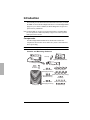
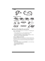
DriveRight OBDII Installation Guide
FCC Part 15 Class B Registration Warning
This equipment has been tested and found to comply with the limits for a Class B digital device, pursuant to Part 15 of the
FCC Rules. These limits are designed to provide reasonable protection against harmful interference in a residential installation. This equipment generates, uses, and can radiate radio frequency energy and, if not installed and used in accordance with the instructions, may cause harmful interference to radio communications.
However, there is no guarantee that interference will not occur in a particular installation. If this equipment does cause
harmful interference to radio or television reception, which can be determined by turning the equipment on and off, the
user is encouraged to try to correct the interference by one or more of the following measures:
•
Reorient or relocate the receiving antenna.
•
Increase the separation between the equipment and receiver.
•
Connect the equipment into an outlet on a circuit different from that to which the receiver is connected.
•
Consult the dealer or an experienced radio/TV technician for help.
Changes or modification not expressly approved in writing by Davis Instruments may void the warranty and void the
user's authority to operate this equipment.
© Davis Instruments Corp. 2007. All rights reserved.
DriveRight OBDII Installation Guide
Rev. D (February 15, 2007)
Product # 8126OBD
Document Part Number: 07395.198
This product complies with the essential protection requirements of the EC
EMC Directive 89/336/EC.
EMC Directive 95/54/EC (Emark)
Tested to comply
with FCC standards
FOR HOME OR OFFICE USE
DriveRight is a registered trademark of Davis Instruments Corp., Hayward, CA.
Velcro is a trademark of Velcro Industries, Manchester, NH.
Information in this document subject to change without notice.
Introduction
This manual provides instructions and information necessary to install
the OBD version of the DriveRight 600E device. The DriveRight OBD
plugs into your vehicle’s OBDII (On-Board Diagnostics II) port for a
quick and easy installation.
Note: DriveRight OBD only functions in vehicles equipped with a compatible OBDII
port. See “Appendix 1: OBDII Compatibility” on page 10 for a list of supported
OBDII protocols and vehicles.
Components
Your DriveRight OBD installation kit should come with all the
components shown below. Please make sure you have all listed items
before proceeding.
Note: Hardware includes spare pieces not required for all installation.
Console and Mounting Hardware
Visor Clip
Right Angle Adapter Bracket
DriveRight Display
Battery
(CR123
3V Lithium)
Mounting Bracket
#6 x 1/2" Pan Head
Self-Tapping Screws (3)
Velcro® Tape (4 pair)
Double-Sided Foam Tape (4 strips)
6-32 x 1/2" Flat Head
Machine Screws (3)
#6 x 1/2" Flat Head
Self-Tapping Screws (3)
Tie Wraps (12)
6-32 Nuts (3)
#6 Split Lock Washers (6)
#6 Flat Washers (6)
1
Cables
OBD Cable
DriveRight
Adapter Cable
Wiring Components
Red +12V Wire
with Fuseholder (22 AWG)
Blue Wire (2) with Fuseholder (22 AWG)
Black Ground Wire
(22AWG)
Spade Terminal Sets:
#8-10 Studs
(3.5 - 5 mm)
1/4" Studs
(6 mm)
Fuses (4)
(3AG 1-1/4 x 1/4",
.25A, Slo-Blo)
Insulated Male Disconnects
(18-22AWG)
T-Tap Disconnects:
In-Line Splice (3)
Butt Splices (5)
(26-22AWG or 24-20AWG)
Blue
(14-16AWG)
Red (3)
(18-22AWG)
Additional DriveRight Documentation
Refer to the following documents for information on configuring and
using your DriveRight:
• The DriveRight 600E User’s Guide included with your unit.
• The Online Help System in the DriveRight software.
• The DriveRight FMS User’s Manual located in an Adobe Acrobat
PDF file in your DriveRight program directory.
Tools and Materials Needed
DriveRight installation may require some or all of the following tools
and materials. Please review the installation instructions and make sure
you have all necessary items before proceeding with the installation.
All Installations
• Electric Drill with 7/64'' (2.5 mm) Drill Bit - Used to drill the tap
holes for #6 self-tapping screws.
• Medium Phillips Screwdriver
• Pliers
2
Installations using Adapter Cable Digital Inputs
If you are using the adapter cable digital inputs in your installation, the
following additional tools and other items may also be required:
• Crimping Tool
• Multimeter
• Fuse Tap - Required to obtain +12 V from the fuse panel.
Planning the Installation
Installation of theDriveRight OBD is simple. Unless you are using the
two digital inputs on the adapter cable, you only need to plug the OBD
cable into your vehicle’s OBDII port and then install the DriveRight
console.
The digital inputs on the DriveRight 600E adapter cable may be used to
monitor any 12 VDC electrical device or accessory in the vehicle, but
they are typically used for monitoring accessories like the brake lights,
headlights, or seat belts.
To install DriveRight OBD:
1. Plug the OBD cable into your vehicle’s OBDII port.
2. Connect the digital inputs (if used).
3. Install the DriveRight console in the vehicle.
4. Test the DriveRight installation.
3
Wiring Diagram
The diagram below is an example of DriveRight OBD wiring.
DriveRight Device
Adapter Cable
(DriveRight 600 or 600E)
Butt
Splices
Green (4)
Blue Wires
with
In-Line
Fuses
Digital
Inputs
1
Yellow
2
Ground
Black
Red
Spade
Terminal
OBD Cable
Connect
to
OBDII
Port
Red Wire with
Fuseholder
In-Line Unswitched
Splice
+12V
Red
Procedure 1: Connect OBD Cable to OBDII Port.
1. Locate the OBDII port in the vehicle.
The OBDII port will be located within 3 feet of the steering wheel,
usually within the general area indicated by the dotted line in the
illustration below. The port should be easily accessible by a person
sitting in the driver’s seat without the use of tools.
OBDII Port
4
Look in the follow areas if you have trouble finding the OBDII port:
• Under the dash
• In front of the passenger seat
• Behind the ash tray
• Behind a small access panel in the dash
• In or around the center console
2. Plug the OBD cable into the port.
Indicator Light
OBDII Port
OBD Cable
Note: The indicator light blinks three times when first plugged in, then blinks twice per
second until the connector establishes communications with the OBDII computer.
When communication has been established, the indicator blinks once then
remains off.
Note: The ignition must be ON to establish communication.
Note: When the vehicle is driven, the indicator blinks once for each speed reading.
Procedure 2: Connect the Digital Inputs (if used)
Two digital inputs located on the adapter cable are available to monitor
the on/off state of lights, including brake lights, or of other 12 VDC
electrical accessories. An example of a digital input configuration may
be Digital Input 1 connected to the brake lights while Digital Input 2
connected to the headlights. In the DriveRight Fleet Management Software (FMS), Digital Input 1 is recorded in the GPS table and in the
accident logs. Digital Input 2 is only recorded in the GPS table.
• You can record the digital input status during a trip by enabling GPS
in DriveRight FMS, even if you aren’t using the optional module.
• The adapter cable is required for DriveRight 600E even if you do not
use the digital inputs.
Note: Connecting the digital inputs can be hazardous to both the installer and your
vehicle’s electrical system if not done by an experienced installer. This manual
assumes you are aware of the inherent dangers of working in and around a vehicle and have a working understanding of electricity.
5
1. If you are installing a DriveRight 600E OBD but not using the digital
inputs, go to Step 10 of this procedure.
2. Butt splice the red fuse holder to the red wire from the adapter cable.
3. Tap the red fuse holder to an unswitched +12 V source using the inline splice provided with your DriveRight or using a fuse tap connector (not included) appropriate for your vehicle.
In-Line Splice
Unswitched
+12V
from Vehicle
Trim off flush
stripped wire
Red +12V Wire with Fuseholder
You can obtain +12V from several places. Usually, you can easily
obtain +12V from the fuse box using a fuse tap connector (not supplied) or using the supplied in-line splice connectors to tap into a
known circuit that does not involve safety related equipment such as
headlights, tail lights, air bag, etc. Possible candidate wires include
those from the cigarette lighter, dome light, glove compartment
light, clock, tail gate light, or other convenience functions.
If you are getting +12V from your fuse box, use a fuse tap connector
appropriate for your vehicle.
4. Butt splice the black ground wire from the adapter cable to black
ground wire included with your DriveRight.
5. Crimp a spade
terminal,
included with the
Vehicle
unit, to the other Ground
end of the black
Crimp Tool,
22-18 AWG Position
Spade
wire. Refer to the
(red dot)
Terminal
illustration.
6. Connect the
Black Ground Wire
3/16 - 1/4"
spade terminal to
(22 AWG)
(5 - 6 mm)
a vehicle chassis
ground.
Note: Use a multimeter to test the vehicle chassis ground before connecting to the
ground wire.
6
7. Use the in-line butt splices to connect the blue wires with fuses to the
Green (Digital Input 1) and Yellow (Digital Input 2) wires from the
adapter cable.
8. Connect Digital Input 1 to the desired circuit.
9. Connect Digital Input 2 to the desired circuit.
10.Connect the digital input cable to the OBD cable.
It is easiest to make the connection by first holding the OBD cable
connector by the housing. Then hold the adapter connector on the
cable itself next to the sliding connector housing and push the two
connectors together. The two cables will lock together when properly connected.
Note: To disconnect the cables, hold the both cables by the housing and pull apart. The
sliding housing on the adapter cable connector will release the lock and allow the
cables to be separated.
To Connect Cables,
Hold as Shown Here
OBD Cable
Sliding
Connector
Housing
Adapter Cable
Procedure 3: Install the DriveRight Console
1. The DriveRight console can be mounted in a number of places,
including the top of the dash, on the face of the dash, or on a sun
visor. Some of the different mounting choices are illustrated below
and on the following page:
Face of Dashboard Mounting Options
OR
Mounting
Bracket
Double-Sided
Foam Tape
Mounting
Bracket
Flat Head Self-Tapping Screw (2x)
7
Top of Dashboard Mounting Using Brackets or Velcro™
Pan Head Self-Tapping Screw
Split-Lock Washer
Flat Washer
Hex Nut
Split-Lock Washer
Flat Washer
Right Angle
Adapter Bracket
Loops
Hooks
Mounting Bracket
Flat Head Machine Screw
Bracket Mounting
Sun Visor Mounting
Visor Clip
OR
3 Bumps
(to hold clip)
2. Insert the battery into the DriveRight console.
8
Velcro Mounting
3. Connect the DriveRight console cable to the adapter cable.
Sliding Connector
Housing
OBD or Adapter Cable
Console Cable
Hold cables as shown to connect. The connector housing on the console
cable slides back when you make the connection, allowing the cables to lock together.
Note: To disconnect the cables, hold the both cables by the connector housing and pull
apart. The sliding housing on the console cable connector will release the lock
and allow the cables to be separated.
Once plugged in, the console should “wake-up” into the Current
Readings screen. If the display remains blank, make sure the battery
is properly installed in the unit. If it is, try pressing MODE. If the
screen remains blank after pressing MODE, press both MODE and
PLUS simultaneously. If it remains blank after that, check the
OBDII port connection.
Procedure 4: Test the Installation
1. Take a test drive and verify that the console displays vehicle speed.
2. If the speed shown in the DriveRight console appears to be off,
check the console’s calibration. You can calibrate DriveRight in the
vehicle using the instructions in your DriveRight User’s Guide, but
you will have much better accuracy with the DriveRight OBD if you
calibrate it in the DriveRight software using the following settings:
• PPM (pulses per mile) = 75,000
• PPR (pulses per reading) = calculated by software
• Calibration Number = calculated by software
Note: If you are using DriveRight FMS 3.1 or later, just select the “OBD” installation
method in the Device Settings dialog box when you configure the DriveRight
console.
9
Appendix 1: OBDII Compatibility
Use this list to verify the compatibility of your vehicle’s OBDII port
with DriveRight OBD.
Supported OBDII Protocols
•
•
•
•
•
J1850-41.6 (PWM)
J1850-10.4 (VPW)
ISO9141
KWP2000 (ISO 14230)
CAN (Controller Area Network - ISO11898)
Supported US Vehicles
• Most domestic and import vehicles, 1996 or later
Supported Vehicles Outside of the US
• In Europe, some 1996 and later vehicles and most 2000 and later
vehicles compliant with the supported protocols listed above
• Outside of the US and Europe, most 1996 and later vehicles compliant with supported OBDII protocols
10
Technical Support
If you are experiencing problems with your DriveRight, first check the
cable connections and verify the calibration settings. If you are unable
to solve the problem, please call Davis Technical Support. We’ll be
glad to help. Most questions can be answered on the phone. You can
also email us for support, or visit our website. Sorry, we are unable to
accept collect calls.
Note: Please do not return items for repair without prior authorization.
(510) 732-7814 – Monday through Friday, 7:00 a.m. to 5:30 p.m.
Pacific Time.
(510) 670-0589 – Fax to Technical Support.
[email protected] – E-mail to Technical Support.
[email protected] – E-mail to Davis Instruments.
www.davisnet.com – Product documentation is available on the DriveRight Support section of our website. Watch for FAQs and other
updates.
11
Installation Notes:
12
Installation Notes:
13
Installation Notes:
14