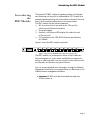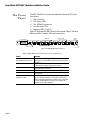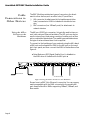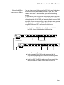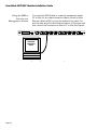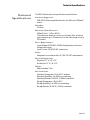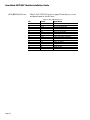
1
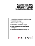
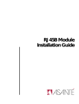
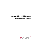
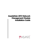
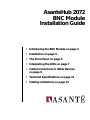
AsantéHub 2072
BNC Module
Installation Guide
• Introducing the BNC Module on page 3
• Installation on page 4
• The Front Panel on page 6
• Interpreting the LEDs on page 7
• Cable Connections to Other Devices
on page 8
• Technical Specifications on page 11
• Cabling Limitations on page 13
AsantéHub 2072 BNC Module Installation Guide
Technical Support
Asanté Technologies is committed to providing you with reliable
products and excellent technical support. Please contact us with
any questions, concerns, or suggestions.You can reach us by
phone, letter, or electronic mail, from 6:00 AM to 5:00 PM, PST at:
Technical Support
Asanté Technologies, Inc.
821 Fox Lane
San Jose, CA 95131
(800) 622-7464
AppleLink address: ASANTE.TECH
Internet address: [email protected]
Please have the model number and PROM revision level prior to
contacting technical support.
Tell Us What You Think
There’s always room for improvement and Asanté Technologies is
always interested in your comments and suggestions about our
product documentation. If you take the time to make suggestions,
we will take the time to read and consider them for new documentation releases.
Do us a favor and read through this Installation Guide and think
about these questions:
1
2
What do you like best about this Guide?
3
What is the most needed improvement you would make to
this Guide?
What do you think is the least valuable or weakest part of
this Guide?
Think about your answers and then give us a ring.
You can fax your comments and suggestions to:
Asanté Technologies
Attn: Technical Publications
(408) 432-1117
or E-mail them through Internet to:
[email protected]
Page 2
Introducing the BNC Module
Introducing
the
BNC Module
The Asanté 2072 BNC multiport repeater module is a single-slot
card that plugs into any slot in the AsantéHub 2072 chassis. As a
separate repeater/retiming unit, this module continues to function
even if other modules malfunctions in the same chassis.
The BNC module has the following features:
❏
AUI connector, which can serve as the 13th port for
uplinking to an Ethernet backbone
❏
Hot swap capable
❏
Partition, Link/Receive LEDs display link status for each
of the ten ports
❏
Full compliance with IEEE 802.3 Ethernet specifications
for 10Base2
Figure 1 shows the BNC module, single-slot.
UPLINK 0
AUI
PARTITION
AH2072H10-BNC
PARTITION
PARTITION
PARTITION
PARTITION
PARTITION
PARTITION
PARTITION
PARTITION
PARTITION
SEG1
1
2
3
4
5
6
7
8
9
10
SEG 0
LINK/RECEIVE
LINK/RECEIVE
LINK/RECEIVE
LINK/RECEIVE
LINK/RECEIVE
LINK/RECEIVE
LINK/RECEIVE
LINK/RECEIVE
LINK/RECEIVE
LINK/RECEIVE
Figure 1 The Asanté BNC Module (Ten-Port, Single-slot)
The BNC module can be assigned to either of the chassis’ two
Ethernet segments or it can remain isolated from a segment for
testing or balancing traffic.You can connect to other devices, such
as computers and printers, using thin Ethernet.
You can access individual port information through the Network
Management Module by running AsantéView’s In-Band and or Outof-Band network management software.
❖ Important: All
BNC ports are terminated internally by a
50 ohm resistor. ❖
Page 3
AsantéHub 2072 BNC Module Installation Guide
Installation
Grounding
Requirements
Checking Package
Contents
Required Tool
Page 4
The BNC module installation consists of a few basic steps:
❏
Grounding yourself
❏
Checking the package contents
❏
Installing the module and checking the LEDs
❏
Connecting the module to other devices
Before unpacking or handling the module, you must attach the
grounding strap provided to your wrist and then touch the rack
mount or a piece of metal to discharge static electricity from your
body or clothes.The chassis should already be grounded.
The BNC Module package includes:
❏
BNC Module in anti-static packaging
❏
This installation guide
❏
Warranty card
❏
Grounding strap
While you can hand-tighten the screws to fasten the module to the
chassis, it is recommended that you use #1 slot screwdriver.
Installation
Installing the
BNC Module
This installation assumes that you have already installed the 2072
chassis.
To install the 2072 BNC Module, do the following steps:
Make sure the Asanté 2072 Hub’s power is turned on. Having the power already turned on allows the LEDs on the
module to light when installed.
1
2
Observing the anti-static procedures, remove the module
from its anti-static packing.
❖ Note: Handle the module only by its edges. Do not touch
chips or connectors.❖
❖ Warning: Do not force the module into a slot. Forcing
the module into a slot can damage the backplane.❖
3
Align the module to the inside edges of the card guides to
any available slot in the chassis. Gently slide the module in
until you can begin tightening the screws. See Figure 2.
1
UPLINK 0
AUI
UPLINK 0
AUI
1
UPLINK 0
AUI
PARTITION
AH2072H10-BNC
AH2072H12-RJ45
2
PARTITION
3
4
5
6
7
8
PARTITION
1
1
9
2
PARTITION
2
10
11
3
PARTITION
4
3
5
4
PARTITION
6
7
5
8
6
PARTITION
PARTITION
9
10
7
LINK/RECEIVE
LINK/RECEIVE
LINK/RECEIVE
LINK/RECEIVE
LINK/RECEIVE
LINK/RECEIVE
PARTITION
3
4
5
6
7
8
11
2
3
4
5
6
7
8
9
10
11
12
12
SEG 0
10BASET PORTS
1
UPLINK 0
AUI
3
4
5
6
7
8
2
3
4
5
6
7
8
9
10
11
12
SEG1
9
10
11
12
SEG 0
LINK/RECEIVE
AH2072H12-RJ45
10BASET PORTS
UTILIZATION %
1
SNMP PORT
3
5
RS-232
UTILIZATION %
10 20 30 50 65+
1
3
5
10 20 30 50 65+
AMS LINK
OUT OF
BAND
UP = THROUGH
DOWN = END
PARTITION
SEGMENT O
LINK/RECEIVE
MSG
AH2072NMM
LC = Late Collision
MC = Misaligned CRC
RF = Runts/Fragments
SM = Short Event/Missing SFD
LC MC RF SM
10
LINK/RECEIVE
SEG 0
SEG1
10
PARTITION
2
SEG1
SEG1
LINK/RECEIVE
10BASET PORTS
9
LINK/RECEIVE
1
PARTITION
12
9
LINK/RECEIVE
PARTITION
2
AH2072H12-RJ45
RESET
11
8
SEG 0
LINK/RECEIVE
1
CPU
PARTITION
12
LINK/RECEIVE
1
3
SEGMENT CONTROL
PRESS BOTH BUTTONS TO PROGRAM
SEG1
SEGMENT 1
5 10+
COLLISION %
LC MC RF SM
1
3
5 10+
COLLISION %
SETUP
UP = AMS PORT
DOWN = SETUP
SELECT
SLOT
CHANGE
SEGMENT
SEG 0
Figure 2 Installing the BNC Module
4
Whether you use your screwdriver or hand-tighten the
module to the chassis, make sure you fasten both screws in
unison and apply the same amount of torque so that the
module attaches evenly to the chassis.
5
Make sure that one of the green segment LEDs lights.This
indicates that the module has been properly connected to
the backplane and is attached to one of the two segments.
(As a default, Segment 1 LED will light.)
Page 5
AsantéHub 2072 BNC Module Installation Guide
The Front
Panel
The BNC Module front panel provides the following LEDs and
connectors:
❏
AUI connector
❏
AUI Uplink LEDs
❏
Ten 10Base2 connectors
❏
Link/Receive LEDs
❏
Segment LEDs (1 and 2)
Figure 3 illustrates the BNC Module front panel;Table 1 lists and
defines the BNC module LEDs and connectors.
BNC Port
AUI Connector
UPLINK 0
AUI
PARTITION
AUI Uplink
LED
PARTITION
PARTITION
PARTITION
PARTITION
PARTITION
PARTITION
PARTITION
2
3
4
5
6
7
8
9
LINK/RECEIVE
LINK/RECEIVE
LINK/RECEIVE
LINK/RECEIVE
LINK/RECEIVE
LINK/RECEIVE
LINK/RECEIVE
LINK/RECEIVE
Link/Receive LED
Table 1 BNC Module Front Panel Controls and Indictors
Name
Function
AUI Connector
Serves as the uplinking port to a network backbone.
Recessed mini MAU slot
Functions as a compartment for housing the recessed
mini MAU.
Ten ports; each can be connected to a network device or
to other hubs for daisy chaining via a MAU.
If active MAU is attached, this LED remains lit, indicating that the link is enabled.
Ten LEDs indicating partitioning ports on the module.
Ten LEDs indicating link connection and traffic passing
over the port.
Remains lit to display which backplane a segment
(Seg1 or Seg2) the module is currently connected to.
AUI Uplink LED
Partition LEDs
Link/Receive LEDs
Segment 1 LED
Segment 2 LED
Neither segment LEDs light if module is not connected
to any of the backplanes, however, the module still
functions as an active repeater.
Page 6
10
SEG 0
Figure 3 BNC Module Front Panel
BNC Connectors
PARTITION
SEG1
1
LINK/RECEIVE
AH2072H10-BNC
PARTITION
SEG1
LED
Partition LED
LINK/RECEIVE
SEG2
LED
Interpreting the LEDs
Interpreting
the LEDs
The LEDs give information about the status of a particular unit or
function. Each 2072 BNC Module has a set of 10 link/partition
LEDs which display port status.
In addition, there are two LEDs which represent AUI Port Link and
Partition status, and two LEDs used to indicate on which Ethernet
segment the repeater card is configured.
LEDs can be categorized into the following four groups:
❏
AUI port partition, link/receive
❏
Port-by-port partition
❏
Port-by-port link/receive
❏
Segment configuration
Table 2 lists and defines the module LEDs.
Table 2 LEDs and Their Meanings
LED
Color/State
Meaning
AUI Uplink
PARTITION LED
Amber, Blinking
Indicates hub has autopartitioned the uplink; possibility of
high collision rate.
Amber, On
Off
Operator has manually partitioned the uplink or a trap has
been sent.
Uplink not partitioned.
Green, On
Green, Blinking
Link or link integrity is disabled.
Traffic over the uplink.
Amber, Off
Indicates normal port operation.
On, Steady
Blinking
Indicates that the slot has been manually partitioned by an
administrator or by a trap.
Indicates autopartitioning.
Green, On
Link is present.
Blinking
Off
Traffic is passing over this port.
Link is not present.
SEG1 and SEG2
Green, On
Indicates on which segment Ethernet is configured.
2 LEDs
Gray, Off
Indicates board is not seated properly or both LEDs could be
intentionally set off by operator. Note that even though a
backplane connection may not exist, the repeater still functions as a full repeater.
AUI Uplink
LINK LED
PARTITION
10 LEDs
LINK/RECEIVE
10 LEDs
Page 7
AsantéHub 2072 BNC Module Installation Guide
Cable
Connections to
Other Devices
The BNC Module provides two types of connectors for attachment to other devices, such as other hubs, PCs, and Macs:
❏
AUI connector for attachment to the backbone and other
hubs (recessed mini- MAU included with double-slot version
❏
BNC connectors (ten 10Base2 ports) for attachment to
network devices
Using the AUI to
Connect to the
Backbone
The AUI port (DB15 pin connector) is typically used to interconnect hubs using an Ethernet backbone.The AUI port can also be
used to interconnect hubs using a variety of media, such as fiber
optics, unshielded twisted-pair.The media type used determines
the type of external transceiver that is required.
To connect to the backbone of your network using the AUI, attach
a MAU such as the Asanté Mini MAU to the AUI port on the module’s front panel, and then connect the MAU to the backbone. See
Figure 4.
❖
Note: Make sure SQE (Signal Quality Error) is disabled on
the MAU when it is attached to the AUI port.❖
UPLINK 0
AUI
PARTITION
LINK
2
PARTITION
3
PARTITION
4
PARTITION
5
PARTITION
6
PARTITION
7
PARTITION
8
PARTITION
9
PARTITION
10
SEG 0
LINK/RECEIVE
AH2072H10-BNC
PARTITION
SEG1
1
LINK/RECEIVE
LINK/RECEIVE
LINK/RECEIVE
LINK/RECEIVE
LINK/RECEIVE
LINK/RECEIVE
LINK/RECEIVE
LINK/RECEIVE
LINK/RECEIVE
SQE
ON
OFF
BNC Backbone
To network devices
Figure 4 Using the AUI to Connect to the Backbone
Shown here is a BNC (thin Ethernet) connection.You can use any
media compatible with the MAU connected to the module AUI
port. Asanté offers Mini MAUs supporting 10BaseT, 10Base2, and
fiber media.
Page 8
Cable Connections to Other Devices
Using the AUI to
Interconnect Hubs
You can interconnect hubs using the AUI Uplink port located on
the module’s front panel. Asanté provides an RJ45, BNC, and
10BaseF Mini MAU to accommodate your backbone cabling
scheme.
To interconnect hubs using the AUI Uplink port, attach a MAU to
the AUI port on the module’s front panel of the first hub. Attach a
cable appropriate for the MAU you are using. Attach another MAU
to the AUI port on the second hub. Figure 5 shows a BNC module
in the first hub connected to a BNC module in the second hub
using BNC MAUs and BNC cabling as the backbone.
❖
Note: Make sure SQE (Signal Quality Error) is disabled on
the MAU when it is attached to the AUI port.❖
Hub 1
PARTITION
PARTITION
PARTITION
PARTITION
PARTITION
PARTITION
PARTITION
PARTITION
PARTITION
UPLINK 0
AUI
SEG1
1
2
3
4
5
6
7
8
9
10
SEG 0
LINK/RECEIVE
AH2072H10-BNC
LINK
PARTITION
LINK/RECEIVE
LINK/RECEIVE
LINK/RECEIVE
LINK/RECEIVE
LINK/RECEIVE
LINK/RECEIVE
LINK/RECEIVE
LINK/RECEIVE
LINK/RECEIVE
SQE
ON
OFF
To network devices
Thin Ethernet cable
Hub 2
PARTITION
PARTITION
PARTITION
PARTITION
PARTITION
PARTITION
PARTITION
PARTITION
PARTITION
UPLINK 0
AUI
SEG1
1
2
3
4
5
6
7
8
9
10
SEG 0
LINK/RECEIVE
AH2072H10-BNC
LINK
PARTITION
LINK/RECEIVE
LINK/RECEIVE
LINK/RECEIVE
LINK/RECEIVE
LINK/RECEIVE
LINK/RECEIVE
LINK/RECEIVE
LINK/RECEIVE
LINK/RECEIVE
SQE
ON
OFF
To network devices
Figure 5 Using the AUI to Interconnect Hubs
❖
Note: Use Asanté Mini MAUs that are appropriate for
your backbone cabling type when interconnecting hubs
on the same backbone.
❖ Note:The BNC Mini MAU can be manually terminated by
setting the switch located on the side of the MAU.❖
Page 9
AsantéHub 2072 BNC Module Installation Guide
Using the BNC to
Connect to a
Management Station
To connect the BNC Module to a network management station
(PC or Mac) for an in-band connection, attach one end of a thin
Ethernet cable to a BNC port on the module’s front panel. Connect the other end of the thin Ethernet cable to a T-connector, and
then connect the T-connector to either a PC or Mac. See Figure 6.
UPLINK 0
AUI
PARTITION
2
PARTITION
3
PARTITION
4
PARTITION
5
PARTITION
6
PARTITION
7
PARTITION
8
PARTITION
9
PARTITION
10
SEG 0
LINK/RECEIVE
AH2072H10-BNC
PARTITION
SEG1
1
LINK/RECEIVE
LINK/RECEIVE
LINK/RECEIVE
LINK/RECEIVE
LINK/RECEIVE
LINK/RECEIVE
LINK/RECEIVE
LINK/RECEIVE
LINK/RECEIVE
AsantéView
Management
Station
Figure 6 Using the BNC to Connect to a Management Station (PC or Mac)
Page 10
Technical Specifications
Technical
Specifications
The BNC Module technical specifications are as follows:
Standards Supported:
IEEE 802.3 Ethernet specifications for thin Ethernet (10Base2)
media.
Data Rate:
10 Mbps
Maximum Cable Distances:
10Base2 (thin) -- 185m (605 ft.)
This maximum distance is on a per port basis. Each of the ten
ports supports up to 29 devices on a total cable length of up to
185 meters.
Power Requirements:
Input Voltage: 90-230 VAC, 50-60Hz Single phase; continuous
voltage input range
Input Current: 3A @ 100 VAC (maximum)
Safety:
Designed in accordance with UL,CSA,TUV/IEC requirements.
Physical Dimensions:
Single-slot: 17” x 0.9” x 12”
Double-slot: 17” x 1.8” x 12”
Weight:
Approximately 2 lbs.
Environmental:
Operating Temperature: 0° to 40° C ambient
Operating Humidity: 5 to 85% noncondensing
Operating Altitude: 10,000 ft. (3,048m) maximum
Storage Temperature: -30° to 80° C
Storage Humidity: 5 to 90% noncondensing
Storage Altitude: 25,000 ft. (7,620m) maximum
Page 11
AsantéHub 2072 BNC Module Installation Guide
AUI (DB-15) Pinouts
Table 3,“AUI (DB-15) Pinouts,” on page 12 lists the pin, circuit,
and signal name for the AUI pins.
Table 3 AUI (DB-15) Pinouts
Page 12
Pin
Circuit
Signal Name
03
10
11
05
12
04
07
15
08
02
09
01
06
13
14
Shell
DO+
DODO S
DI+
DIDI S
CO+
COCO S
CI+
CICI S
VC
VP
VS
PG
Data Out positive
Data Out negative
Data Out circuit Shield
Data In circuit positive
Data In circuit negative
Data In circuit Shield
Control Out positive (optional)
Control Out negative (optional)
Control Out Shield (optional)
Control In positive
Control In negative
Control In Shield
Voltage Common
Voltage Plus
Voltage Shield
Protective Ground
Cabling Limitations
Cabling
Limitations
Table 5 lists the IEEE standards used to determine how networks
should be configured when using coaxial cable connections.
Table 4 IEEE 802.3 Ethernet Standards
Data rate
Cable length per
trunk segment
Nodes per trunk
segment
Min. distance
between nodes
Max. number of
trunk segments
Max. network trunk
length
Cable type
Transceiver type
Connector
10Base5
Ethernet
(Thick)
10 Mbits
500m
10Base2 Thin
Coax (Standard)
10 Mbits
185m
10Base2 Thin 10BaseT
Coax
(Extended)
10 Mbits
10 Mbits
300m
100m
100
30
100
1
2.5m
.5m
.5m
n/a
5
2500m
3 (+ 2 repeater 3 (no
n/a
only)
repeater only)
925m
900m
n/a
dbl. shield.4”
coax
external with
drop cable
clamp-on
sgl. shield.2”
coax
recessed or
external
BNC
sgl. shield.2”
coax
recessed or
external
BNC
solid conductor
n/a
RJ-45
❖Note: Extended
Length networks cannot contain any
repeater-only segments.❖
Page 13
AsantéHub 2072 BNC Module Installation Guide
Manual P/N 06-00086-00
Revision B
Page 14