1
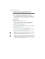
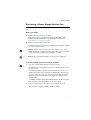
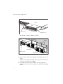
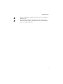
Removable Power Supply and Fan
Installation Guide
AT-PWR01
AT-PWR02
AT-PWR05
AT-FAN01
AT-FAN03
Removable Power Supply and Fan
Installation Guide
AT-PWR01
AT-PWR02
AT-PWR05
AT-FAN01
AT-FAN03
Download the complete document set from
www.alliedtelesis.com/support/software
Removable Power Supply and Fan
Removable Power Supply and Fan Installation Guide
Document Number C613-04057-00 REV P
© 2008 Allied Telesis, Inc. All rights reserved. No part of this publication may be
reproduced without prior written permission from Allied Telesis, Inc.
Allied Telesis, Inc. reserves the right to change specifications and other
information in this document without prior written notice. The information
provided herein is subject to change without notice. In no event shall Allied
Telesis, Inc. be liable for any incidental, special, indirect, or consequential
damages whatsoever, including but not limited to lost profits, arising out of or
related to this manual or the information contained herein, even if Allied Telesis,
Inc. has been advised of, known, or should have known, the possibility of such
damages.
Allied Telesis, AlliedWare, AlliedWare Plus, and SwitchBlade are trademarks or
registered trademarks in the United States and elsewhere of Allied Telesis, Inc.
Adobe, Acrobat, and Reader are either registered trademarks or trademarks of
Adobe Systems Incorporated in the United States and/or other countries.
Microsoft and Visio are either registered trademarks or trademarks of Microsoft
Corporation in the United States and/or other countries. Additional brands,
names and products mentioned herein may be trademarks of their respective
companies.
2
Installation Guide
Contents
About this Guide .............................................................................................................. 4
Compatible Switches ....................................................................................................... 4
Package Contents ............................................................................................................. 5
Installing a Power Supply Unit or Fan .......................................................................... 6
Connecting an AC power supply .................................................................................. 9
Connecting a PWR01 DC power supply .................................................................. 13
Connecting a PWR05 DC power supply .................................................................. 16
Checking LEDs ................................................................................................................ 18
Removing a Power Supply Unit or Fan ...................................................................... 21
Troubleshooting .............................................................................................................. 24
Obtaining Documentation and Resources ............................................................... 25
Standards .......................................................................................................................... 27
EC Declaration of Conformity .................................................................................... 28
3
Removable Power Supply and Fan
About this Guide
This Installation Guide describes how to install the following PSUs and fans:
■
AT-PWR01 PSU, either AC or DC power supply unit
■
AT-PWR02 PSU, AC only
■
AT-PWR05 PSU, either AC or DC power supply unit
■
AT-FAN01, fan-only module
■
AT-FAN03, chassis fan module
Compatible Switches
The following table shows which models of PSUs and fans are appropriate for
individual switches.
Switch
PWR01
PWR02
PWR05
AT-8948
9
9
x900-48FE
9
9
9
x900-48FS
FAN01
9
AT-9924T
9
9
AT-9924SP
9
9
AT-9924Ts
9
9
x900-24XT
9
9
x900-24XT-N
9
9
x900-24XS
9
9
SwitchBlade® x908
FAN03
9
9
You can download complete documentation for these switches from
www.alliedtelesis.com/support/software. For more information about the
documentation and other resources, see “Obtaining Documentation and
Resources” on page 25.
4
Installation Guide
Package Contents
Depending on the model, switches are shipped with a single supply unit (PSU),
either AC or DC. Some models also have fan-only modules (FOM), chassis fan
modules, or blanking plates.
■
The AT-8948, AT-9924Ts, x900-24XT, x900-24XT-N, and x900-24XS
switches have a PSU and a FOM installed.
■
The x900-48FE, x900-48FS, AT-9924T, and AT-9924SP switches have a PSU
and a blanking plate installed.
■
The SwitchBlade® x908 is shipped with dual chassis fan modules and
blanking plates, but no PSUs.
The following items are included with each factory-installed PSU. Contact your
authorised Allied Telesis distributor or reseller if any are damaged or missing.
■
one AC power cord (AC models)
■
one power cord retaining clip (AC models)
■
one warranty card
The following items are included with PSUs when purchased separately:
■
one AC power cord (AC models)
■
one power cord retaining clip (PWR01 and PWR02 AC models only)
■
one clip-on ferrite core (PWR05 only)
■
this Installation Guide
■
one warranty card
The following items are included with fans when purchased separately:
■
this Installation Guide
■
one warranty card
5
Removable Power Supply and Fan
Installing a Power Supply Unit or Fan
Use these instructions to install PSUs, chassis fan modules and FOMs.
■
Do not combine PWR01 and PWR02 PSUs in the same switch.
■
For the SwithBlade x908 or the x900-24XT and x900-24XS running
AlliedWare Plus Operating System you may combine AC and DC PSUs in
the same switch. Do not combine AC and DC PSUs in the same switch for
any other models.
Before you begin
■
Read the safety information for the switch.
Safety information is in the x900 Series Switch and SwitchBlade® x908
Installation and Safety Guide. You can download this document from
www.alliedtelesis.com/support/software.
■
Gather necessary tools and equipment.
You will need an appropriate flat-bladed or Phillips (#1) screwdriver to tighten
or loosen the captive screws.
■
Verify the package contents if you have not already done so.
See “Package Contents” on page 5. Contact your authorised Allied Telesis
distributor or reseller if items are damaged or missing.
■
Remove the unit from its packing material in an anti-static environment.
Caution Follow correct anti-static procedures. Failure to do so could
damage the PSU, fan, or switch. If you are unsure about correct procedures,
contact your authorised Allied Telesis distributor or reseller.
Caution When adding or replacing power supplies, keep your hands and
fingers out of the power supply bays. After installing a PWR05 power supply,
use a screwdriver to tighten the captive screw such that a screwdriver will be
required to remove the PSU at a later date.
6
Installation Guide
Installing a PWR01, PWR02, or FAN01
1.
If there is a PSU, fan or blanking plate in the bay you wish to install the unit,
first remove the old unit, following the steps described in section
“Removing a Power Supply Unit or Fan” on page 21.
2.
Insert the new PSU or fan unit, and carefully slide it into the bay.
Insert it slowly, being sure to keep it straight. Firmly press the unit until the
faceplate engages, or nearly engages, the chassis. Forcing a misaligned unit
into the bay is likely to damage both the unit and chassis.
Note that when you have only one PSU installed in the AT-9924T and
AT-9924SP switches, it must be installed in bay 2 to optimise cooling.
3.
Secure the unit in the switch by tightening the captive screws on the
faceplate.
Switch
PSU
Captive screw
Captive screw
7
Removable Power Supply and Fan
Installing a PWR05 or FAN03
1.
If there is a PSU, fan or blanking plate in the bay you wish to install the unit,
first remove the old unit, following the steps described in section
“Removing a Power Supply Unit or Fan” on page 21.
PSU bays
PSU
Service
access
panels
Chassis fan
Captive screw
Captive screw
2.
Insert the new PSU or chassis fan module, and carefully slide it into the bay.
If you are installing a PSU, unlock the latch on the PSU first by loosening the
captive screw.
Insert the PSU or fan module slowly, being sure to keep it straight. Firmly
press the unit until the faceplate engages, or nearly engages, the chassis.
Forcing a misaligned unit into the bay may damage both the unit and chassis.
3.
8
Secure the unit in the switch by tightening the captive screw(s) on the
faceplate. On the PWR05, use a screwdriver to tighten the captive screw
such that a screwdriver will be required to remove the PSU at a later date.
Installation Guide
Connecting an AC power supply
Follow these instructions to connect an AT-PWR01, AT-PWR02, or AT-PWR05
AC PSU to an AC power supply:
Warning The AT-PWR01 AC PSU has a fuse rating of 250V, 5A for FH101 and
FH102.
Warning The AT-PWR01 AC PSU has double pole/neutral fusing. Electric
shock is possible since there are dual primary fuses, one on the phase circuit and
one on the neutral circuit. If the neutral opens, the phase may still be live.
Warning When x900-24 units are connected with VCS stacking cables (XEMSTK-CBL) ensure that all the PSUs are appropriately grounded. This is to avoid
large circulating ground currents that could damage the stacking cables. To
achieve this ensure that:
■
■
AT-PWR01 AC is grounded by the 3-pin AC power connector
All grounding points are at the same ground level. That is, all power
connectors share a common power distribution unit.
Warning For x900-24 models, when using an AT-PWR01 AC power supply and
an AT-PWR01 DC power supply in the same switch, then the ground-terminal of
the DC power connector must be connected to the same ground as the AC
ground pin of the AC power connector.
If this is not possible, then you must ground the AT-PWR01 AC only, and leave
the AT-PWR01 DC power connector ungrounded. In this case, as a safety
precaution, ensure that the rack is also grounded.
Warning For SwitchBlade x908 models, when using an AT-PWR05 AC power
supply and an AT-PWR05 DC power supply in the same switch, then the groundterminal of the DC power connector must be connected to the same ground as
the AC ground pin of the AC power connector.
If this is not possible, then you must ground the AT-PWR05 AC only, and leave
the AT-PWR05 DC power connector ungrounded. In this case, as a safety
precaution, ensure that the rack is also grounded.
Warning For SwitchBlade x908 AC models, the grounding stud on the rear of
the device is provided for situations where an additional ground is required. The
device must be powered from a grounded 3 wire AC source via the AC power
cable and connector.
9
Removable Power Supply and Fan
Warning When SBx908 devices are connected with VCS stacking cables (either
HS-STK-CBL or XEM-STK-CBL), each individual stack member chassis must be
additionally grounded by using the rear grounding-terminal on each device. In
order to avoid large circulating ground currents, the wires of each grounding
cable must be 18AWG or thicker.
10
Installation Guide
Connecting a PWR01 or PWR02
1.
Plug the supplied AC power cord into the power inlet on the PSU and
attach the retaining clip.
2.
Connect the power cord to the main power source.
3.
The PSU LED on the front panel of the switch lights green. If the LED does
not light, refer to the Hardware Reference for troubleshooting information.
Connecting a PWR05 (AC version only)
The DC earthing connection is not necessary for the SwitchBlade x908 when
using AC PSUs because the chassis is grounded through the power cords.
1.
Form a loop in the supplied AC power cord at the PSU end and clip the
ferrite core over the looped cord, as shown in the following illustration.
This keeps the ferrite core in its correct position, close to the PSU.
Ferrite core
Looped power cord
11
Removable Power Supply and Fan
2.
Plug the AC power cord into the power inlet on the PSU.
3.
Connect the power cord to the main power source.
4.
Check that the Run/Standby switch is set to the Run position (1). Both the
AC and DC LEDs should be lit.
CAPTIVE
SCREW
RUN/STANDBY
SWITCH
AC
IN
LED
DC
OUT FAULT
LED
LED
Note that when the Run/Standby switch is set to the Standby position (O),
the AC LED lights and the fan spins, but the DC LED does not light and the
PSU does not deliver power to the device.
5.
12
The PSU LED on the front panel of the switch lights green. If the LED does
not light green, check the Run/Standby switch. See the Hardware Reference
for more troubleshooting information.
Installation Guide
Connecting a PWR01 DC power supply
Follow these instructions to connect an AT-PWR01 DC PSU to a DC power
supply. Only trained and qualified personnel should connect a DC power supply.
You need an appropriate DC power source, DC supply cable, ring connectors, a
crimp tool and an appropriate screwdriver to tighten the terminal screws.
For centralised DC power connection, the switch should be installed in
restricted access areas only (such as dedicated equipment rooms or
equipment closets) in accordance with Articles 110-16, 110-17, and 110-18 of
the National Electrical Code, ANSI/NFPA 70.
Power supply specifications:
■
40 to 60V, 48V nominal
■
supports either positive grounded or negative grounded operation
■
a 15Amp certified/listed circuit breaker is required for circuit protection
Supply cable specifications:
■
three-core cable is required
■
minimum core size: 3.3mm2 (12 AWG) high strand count copper wire
■
minimum cable rating: 600V, 90 degrees C
Warning Disconnect the power supply cable before starting this procedure.
1.
Remove the transparent protective terminal cover.
2.
Strip the supply cable wires to expose 7.5mm (0.31 in.) of bare conductor.
Terminate the wire with a nylon insulated solderless ring tongue terminal,
JST FN5.5-5 or equivalent, using a crimp tool.
3.
Connect the ground wire to the ground terminal. Use the diagram on the
rear panel of the switch to identify terminals. Tighten the terminal to
between 2.4 and 4.0 Nm (21.3 and 35.4 lbf in).
Warning In order to avoid damaging the PSU, make sure that the PSU
terminals are wired to the correct polarity.
Warning When x900-24 units are connected with VCS stacking cables
(XEM-STK-CBL) ensure that all the PSUs are appropriately grounded. This
is to avoid large circulating ground currents that could damage the stacking
cables. To achieve this ensure that:
13
Removable Power Supply and Fan
•
AT-PWR01 DC is grounded at the GND terminal. In order to avoid
large circulating ground currents, the wires of each grounding cable
must be 18AWG or thicker.
•
All grounding points are at the same ground level. That is, all power
connectors share a common power distribution unit.
Warning When mounting one or two AT-PWR01 DC PSUs to a grounded
rack, ensure that the ground level of the rack and the DC power connector
are the same.
Warning For x900-24 models, when using an AT-PWR01 AC power supply
and an AT-PWR01 DC power supply in the same switch, then the groundterminal of the DC power connector must be connected to the same
ground as the AC ground pin of the AC power connector.
If this is not possible, then you must ground the AT-PWR01 AC only, and
leave the AT-PWR01 DC power connector ungrounded. In this case, as a
safety precaution, ensure that the rack is also grounded.
Warning When SBx908 devices are connected with VCS stacking cables
(either HS-STK-CBL or XEM-STK-CBL), each individual stack member
chassis must be additionally grounded by using the rear grounding-terminal
on each device. In order to avoid large circulating ground currents, the wires
of each grounding cable must be 18AWG or thicker.
4.
Connect the positive feed to the + (positive) terminal and the negative feed
to the - (negative) terminal. Tighten the terminals to between 2.4 and
4.0Nm (21.3 and 35.4 lbf in).
Note that the DC return input terminal must be connected as an Isolated
DC return (DC-I).
5.
Ensure that there are no exposed cable strands.
6.
Replace the cover. You must replace the transparent plastic terminal cover
before continuing.
7.
Secure the supply cable to the rack framework or a similar object to ensure
that connections are isolated from any force applied to the cable.
8.
Ensure that the circuit breaker for the supply circuit and the Run/Standby
switch on the PSU are off. Press and release the Run/Standby switch so that
it is not pushed in (which is the Off position).
9.
Connect the supply cable wires to the circuit breaker.
10. Turn on the PSU by pushing in the Run/Standby switch.
14
Installation Guide
11. Confirm that the switch is receiving power.
Check that at least one of the PSU LEDs on the front panel of the switch is
lit green. If no LEDs light, refer to the Hardware Reference for
troubleshooting information.
15
Removable Power Supply and Fan
Connecting a PWR05 DC power supply
Follow these instructions to connect an AT-PWR05 DC PSU to a DC power
supply. Only trained and qualified personnel should connect a DC power supply.
For centralised DC power connection, the switch should be installed in
restricted access areas only (such as dedicated equipment rooms or
equipment closets) in accordance with Articles 110-16, 110-17, and 110-18 of
the National Electrical Code, ANSI/NFPA 70.
Warning When mounting one or two AT-PWR05 DC PSUs to a grounded rack,
ensure that the ground level of the rack and the DC power connector are the
same .
Warning For SwitchBlade x908 models, when using an AT-PWR05 AC power
supply and an AT-PWR05 DC power supply in the same switch, then the groundterminal of the DC power connector must be connected to the same ground as
the AC ground pin of the AC power connector.
If this is not possible, then you must ground the AT-PWR05 AC only, and leave
the AT-PWR05 DC power connector ungrounded. In this case, as a safety
precaution, ensure that the rack is also grounded.
Power supply specifications:
■
40 to 60V DC, 48V nominal
■
supports either positive grounded or negative grounded operation
■
a 30Amp certified/listed circuit breaker is required for circuit protection
Warning Always use the cable supplied.
16
Installation Guide
RUN/STANDBY
SWITCH
CAPTIVE
SCREW
DC
IN
LED
DC
OUT FAULT
LED
LED
1.
Ensure that the circuit breaker for the supply circuit and the Run/Standby
switch on the PSU are off (slide to position O).
2.
Plug the DC power cord into the power inlet on the PSU.
3.
Connect the supply cable wires to the circuit breaker and switch the circuit
breaker ON.
4.
Turn on the PSU by sliding in the Run/Standby switch to position 1.
5.
Confirm that the switch is receiving power.
Check that the PSU LED on the front panel of the switch corresponding to
the the PSU bay lights green. If the LED does not light green, check the
Run/Standby switch. See the Hardware Reference for more
troubleshooting information.
17
Removable Power Supply and Fan
Checking LEDs
LEDs on PSUs, fans, and the front panels of switches indicate the operational
status of the devices. After you have installed a PSU or fan and have powered on
the switch, check the LEDs to verify operation by using the following tables.
PWR01 The following table describes LEDs on the PWR01 and PWR02 power supply
PWR02 units.
LED
State
Description
FAULT
Red
The temperature on the PSU has exceeded the limit of
75º C (167º F), or the fan failed.
PWR
GOOD
Green
A PSU is installed in the switch and is delivering power.
PWR05 The following is a diagram of the LEDs in the PWR05 power supply units:
IN OUT FAULT
LED LED LED
POWER
CONNECTOR
18
Installation Guide
PWR05 The following table describes LEDs on the PWR05 AC power supply unit.
AC
LED
~
IN
OUT
FAULT
State
Description
Green
AC input voltage is within 90-264VAC, 47-63Hz.
Off
AC input voltage is outside the acceptable range.
Green
AC output voltage is within 12V +/- 10%.
Off
AC output voltage is outside the acceptable range.
Red
A fault has occurred. There is either a fan failure, or the
temperature has exceeded its limit of 70ºC (158ºF).
Off
No fault conditions detected.
PWR05 The following table describes LEDs on the PWR05 DC power supply unit.
DC
LED
IN
OUT
FAULT
State
Description
Green
DC input voltage is within -40 VDC to -60VDC.
Off
DC input voltage is outside the acceptable range.
Green
DC output voltage is within 12V +/- 10%.
Off
DC output voltage is outside the acceptable range.
Red
A fault has occurred. There is either a fan failure, or the
temperature has exceeded its limit of 70ºC (158ºF).
Off
No fault conditions detected.
FAN01 The following table describes LEDs on the FAN01 fan-only module.
LED
State
Description
FAULT
Red
The fan has failed.
FAN03 The following table describes LEDs on the FAN03 chassis fan module.
LED
State
Description
FAN
STATUS
Red
The fan has failed.
19
Removable Power Supply and Fan
Switch The following table describes how LEDs on the switch report operations and
faults with installed PSUs and FOMs.
LED
State
Description
PSU 1
and
PSU 2
Green
The PSU is installed and supplying power to the switch.
The voltage output is within specification.
Red
One of the following:
Off
20
•
The PSU is installed in the switch, and a fan has
failed or the PSU has exceeded its recommended
temperature threshold of 70ºC (158º F).
•
A FOM is installed in the switch and a fan has failed.
Note that the x900-12XT/S and SwitchBlade x908
switches do not support FOMs.
•
The bay is empty. Applies to AT-8948, AT-9924Ts,
x900-24XT, x900-24XT-N, and x900-24XS
switches which require a FOM when only one PSU
is installed.
•
Dual PSUs are installed, but the PSU is not
receiving power.
One of the following:
•
A FOM is installed and operating at an acceptable
speed. Applies to AT-9924T, x900-48FE, and
x900-48FS.
•
On SwitchBlade x908 switches there is no power
supply in this bay.
Installation Guide
Removing a Power Supply Unit or Fan
Follow these instructions to remove a PSU, chassis fan module, FOM or blanking
plate.
Before you begin
■
Read the safety information for the switch.
Safety information is in the x900 Series Switch and SwitchBlade® x908
Installation and Safety Guide. You can download this document from
www.alliedtelesis.com/support/software.
■
Gather necessary tools and equipment.
You will need an appropriate flat-bladed or Phillips (#1) screwdriver to tighten
or loosen the captive screws.
Caution Follow correct anti-static procedures. Failure to do so could
damage the PSU, fan, or switch. If you are unsure about correct procedures,
contact your authorised Allied Telesis distributor or reseller.
Caution Keep your hands and fingers out of the power supply bays.
To remove a PSU, chassis fan module or FOM
1.
If you are removing a PSU, disconnect the power supply.
For AC PSUs, turn off the main power source to the PSU and disconnect
the power cord.
For PWR01 DC PSUs, push and release the Run/Standby switch to the
Standby (off) position using a small pin. The Run/Standby switch is in the
Run (on) position when it is depressed, and in the Standby (off) position
when it is not depressed. Disconnect the supply cable wires from the
circuit breaker.
For PWR05 DC PSUs, slide the Run/Standby switch to the O (off) position.
Disconnect the power supply cable from the power supply.
2.
Using a screwdriver, loosen the captive screws until fully loosened.
The following is a diagram of PWR01, PWR02 or FAN01
21
Removable Power Supply and Fan
Switch
PSU
Captive screw
Captive screw
The following is a diagram of PWR05 and FAN03
PSU bays
PSU
Service
access
panels
Chassis fan
Captive screw
Captive screw
3.
Remove the PSU, chassis fan module, FOM or the blanking plate from the
switch.
Slide the unit out slowly and carefully. Support the unit from underneath as
you remove it, to prevent it from falling.
4.
22
For all units, with the exception of FAN03, cover empty bays with a
blanking plate, to prevent dust and debris from overheating or damaging the
switch.
Installation Guide
Avoid the spinning blades on FAN03. Contact may cause personal injury or
damage the unit.
Do not operate the switch for extended periods without functioning
chassis fan modules. Doing so will cause the switch to overheat and shut
down, and may damage the switch.
23
Removable Power Supply and Fan
Troubleshooting
If the PSU does not function as expected:
■
Check that all cable connections are correct and secure.
■
On the PWR01 DC model, check that the Run/Standby switch has been
pressed and is in the On position.
■
On the PWR05, check that the Run/Standby switch has been set to Run
(position 1).
■
Check that the PSU is receiving the correct AC voltage (AC models).
■
Check that the PSU is receiving the correct DC voltage (DC models).
■
If LEDs indicate a PSU fault, replace the PSU or have your authorised Allied
Telesis distributor or reseller service it.
Troubleshooting information is also in the x900 Series Switch and
SwitchBlade® x908 Hardware Reference. You can download this document from
www.alliedtelesis.com/support/software.
24
Installation Guide
Obtaining Documentation and Resources
The complete document set for x900 Series switches and SwitchBlade x908
includes:
■
this Installation Guide
■
the x900 Series Switch and SwitchBlade® x908 Installation and Safety Guide,
which describes how to install the switch and includes important safety and
statutory information
■
the x900 Series Switch and SwitchBlade® x908 Hardware Reference, which
contains detailed information on x900 Series and SwitchBlade x908 switches
and their hardware features
■
the x900 Series Switch and SwitchBlade® x908 Expansion Module Installation
Guide, which describes how to install expansion modules in x900 Series and
SwitchBlade x908 switches
■
the AT-9900s Series Switch Expansion Module Installation Guide, which
describes how to install expansion modules in AT-9900s Series switches
■
the x900 Series Switch AlliedWare® Operating System Software Reference, which
contains detailed information on configuring switches running the
AlliedWare operating system
■
the AlliedWare Plus™ Operating System Software Reference, which contains
detailed information on configuring switches running the AlliedWare Plus
operating system
You can download these documents and updates from
www.alliedtelesis.com/support/software.
You need Adobe® Acrobat® Reader® software to view, search, or print these
documents. You can download it from www.adobe.com.
Other resources
How-To Notes describe a range of standard Allied Telesis solutions, and include
technical tips and guides to configuring specific hardware and software features.
You can download the latest How-To Notes from
www.alliedtelesis.com/resources/literature/howto.aspx.
MIBs supported by Allied Telesis products can be downloaded from
www.alliedtelesis.com/support/software.
Microsoft® Visio® stencils for Allied Telesis products can be downloaded from
www.alliedtelesis.com/resources/images/visio.aspx.
25
Removable Power Supply and Fan
AT-TFTP Server for Windows is a TFTP (Trivial File Transfer Protocol) server for
transferring software versions, configuration scripts and other files between a
PC and the switch. You download AT-TFTP Server from
www.alliedtelesis.com/support/software.
CD-ROM
Some products also ship with a CD-ROM containing documentation and
resources.
Contacting us
With locations covering all of the established markets in North America, Latin
America, Europe, Asia, and the Pacific, Allied Telesis provides localized sales and
technical support worldwide. To find the representative nearest you, visit us on
the Web at www.alliedtelesis.com.
26
Installation Guide
Standards
Where applicable, the products in this document meet the following standards:
Category
Approval Agency and Requirement
Safety
UL60950-1
CAN/CSA-C22.2 No. 60950-1-03
EN60950-1
AS/NZS 60950.1
EN 60825-1
EN 60825-2
21 CFR 1040
Electromagnetic
FCC CFR47 Part 15 Class A
EN55022 Class A
VCCI Class A
AS/NZS CISPR22 Class A
CNS 13438 Class A
EN61000-3-2/3
EN55024
ETSI 300 386
Immunity
EN55024
ETSI
ETSI 300 019
ETSI 300 132
WEEE
Meets requirements of Directive 2002/96/EC of the European Parliament
and of the council of 27 January 2003
RoHS
Meets requirement of Directive 2002/95/EC of the European Parliament
and of the council of 27 January 2003
U.S. Federal Communications Commission
RADIATED ENERGY
Note: This equipment has been tested and found to comply with the limits for a Class A digital device
pursuant to Part 15 of the FCC Rules. These limits are designed to provide reasonable protection
against harmful interference when the equipment is operated in a commercial environment. This
equipment generates, uses, and can radiate radio frequency energy and, if not installed and used in
accordance with this instruction manual, may cause harmful interference to radio communications.
Operation of this equipment in a residential area is likely to cause harmful interference in which case
the user will be required to correct the interference at his own expense.
Note: Modifications or changes not expressly approved by the manufacturer or the FCC can void
your right to operate this equipment.
Canadian Department of Communications
This Class A digital apparatus meets all requirements of the Canadian Interference-Causing
Equipment Regulations.
Cet appareil numérique de la classe A respecte toutes les exigences du Règlement sur le matériel
brouilleur du Canada.
27
Removable Power Supply and Fan
EC Declaration of Conformity
We:
ALLIED TELESIS LABS LIMITED
27 NAZARETH AVENUE
CHRISTCHURCH 8024
NEW ZEALAND
Declare under our sole legal responsibility that these products:
AT-PWR01, AT-PWR01-80, AT-PWR02, and AT-PWR05
Power Supply Units
Are in conformity with the essential requirements of directives:
■
2006/95/EC Low Voltage Directive
■
2004/108/EC Electromagnetic Compatibility (EMC) Directive
with reference to the following harmonised standards:
28
■
EN55022: 1998 including A1:2000 and A2:2003
Information Technology Equipment-Radio disturbance
■
EN55024: 1998 including A1:2001 and A2:2003
Information Technology Equipment—Immunity characteristics—Limits and
methods of measurement
■
EN60950-1: 2001 including A11:2004
Information Technology Equipment including electrical business
equipment—General Requirements
■
EN61000-3-2: 2000 including A2:2005
Electromagnetic compatibility (EMC)—part 3-2: Limits for harmonic current
emissions (equipment input current up to and including 16A per phase)
■
EN61000-3-3: 1995 including A1:2001 and A2:2005
Electromagnetic compatibility (EMC)—part 3-3: Limitation of voltage
fluctuations and flicker in low-voltage supply systems for equipment with
rated current up to 16A
Name: Dougal Oliver
On behalf of the Manufacturer
Position:
Manager Engineering Programme
Signature:
Date of issue: 15 December 2008
Place of issue: 27 Nazareth Ave