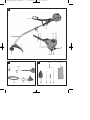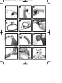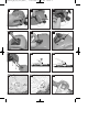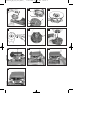
1
Anleitung_BG_PT_3041_SPK1:_ 17.06.2008 11:01 Uhr Bedienungsanleitung Benzin-Motortrimmer Operating Instructions Petrol Power Trimmer Mode dʼemploi de la Débroussailleuse à moteur à essence Istruzioni per lʼuso Tosaerba a filo con motore a benzina Használati utasítás Benzín-motortrimmer Seite 1 � Art.-Nr.: 34.018.10 I.-Nr.: 01018 BG-PT 3041 Anleitung_BG_PT_3041_SPK1:_ 17.06.2008 11:01 Uhr Seite 2 Vor Inbetriebnahme Bedienungsanleitung und Sicherheitshinweise lesen und beachten Read and follow the operating instructions and safety information before using for the first time. Avant la mise en service, lisez le mode dʼemploi et les consignes de sécurité et respectez-les. Prima della messa in esercizio leggete e osservate le istruzioni per lʼuso e le avvertenze di sicurezza. Üzembehelyezés előtt elolvasni és figyelembe venni a használati utasítást és a biztonsági utasításokat. 2 Anleitung_BG_PT_3041_SPK1:_ 17.06.2008 11:01 Uhr Seite 3 A 17 5 18 9 12 7 15 4 6 3 1 8 13 11 2 16 14 B C 10 22 19 1 4 18 17 5 3 23 21 20 20 3 Anleitung_BG_PT_3041_SPK1:_ D1 17.06.2008 11:01 Uhr Seite 4 D2 D3 5 3 6 1 4 E1 1 2 3 1 F1 G A 4 2 E2 E3 F2 F3 H I Anleitung_BG_PT_3041_SPK1:_ 17.06.2008 11:02 Uhr Seite 5 J1 J2 J3 K1 K2 K3 L M1 M2 M4 N1 1 2 M3 5 Anleitung_BG_PT_3041_SPK1:_ N2 17.06.2008 11:02 Uhr Seite 6 N3 N4 B C E E D N6 N5 N7 F O1 O2 1 2 O4 5 6 F 3 O3 4 Anleitung_BG_PT_3041_SPK1:_ 17.06.2008 11:02 Uhr Seite 16 GB Table of contents 1. 2. 3. 4. 5. 6. 7. 8. 9. 16 Safety Regulations Layout and items supplied Intended use Technical data Before starting the equipment Operation Cleaning, maintenance, storage, transport and ordering of spare parts Disposal and recycling Troubleshooting Anleitung_BG_PT_3041_SPK1:_ 17.06.2008 11:02 Uhr Seite 17 GB Important! When using the equipment, a few safety precautions must be observed to avoid injuries and damage. Please read the complete operating instructions and safety regulations with due care. Keep this manual in a safe place, so that the information is available at all times. If you give the equipment to any other person, hand over these operating instructions and safety regulations as well. We cannot accept any liability for damage or accidents which arise due to a failure to follow these instructions and the safety instructions. 18. 19. 20. 21. 22. 23. 1. Safety regulations Important. Due to the high risk of bodily injury to the user, the petrol power scythe must not be used to carry out the following work: to clean (suck up) dirt and debris off walkways, or to chop up tree or hedge clippings. Moreover, the petrol power scythe may not be used to level out high areas such as molehills. For safety reasons, the petrol power scythe may not be used as a drive unit for other work tools or toolkits of any kind. The corresponding safety information can be found in the enclosed booklet. CAUTION! Read all safety regulations and instructions. Any errors made in following the safety regulations and instructions may result in an electric shock, fire and/or serious injury. Keep all safety regulations and instructions in a safe place for future use. Safety devices When working with the equipment, the appropriate plastic guard hood for cutting blade mode or cutting line mode must be fitted to prevent objects being thrown out by the equipment. The integrated blade in the cutting line guard hood automatically cuts the line to the optimum length. 2. Machine description and items supplied (Fig. A – C) 1. 2. 3. 4. 5. 6. 7. 8. 9. 10. 11. 12. 13. 14. 15. 16. 17. Cutting head Cutting line Guard hood Long handle with drive shaft Additional handle Engine switch “ON/OFF” Throttle lever “release” Throttle lever Throttle lever “lock” Choke lever Starter cable Spark plug boot Air filter housing cover Petrol tank Housing for engine cooler and starter Fuel pump “primer” Carrying strap Connecting piece for long handle Combined oil/petrol cylinder Spark plug wrench Allen key Open-ended spanner size 8/10 2-stroke oil 3. Proper use The machine is designed for cutting lawns and grassed areas. The machine is to be used only for its prescribed purpose. Any other use is deemed to be a case of misuse. The user / operator and not the manufacturer will be liable for any damage or injuries of any kind caused as a result of this. Please note that our equipment has not been designed for use in commercial, trade or industrial applications. Our warranty will be voided if the machine is used in commercial, trade or industrial businesses or for equivalent purposes. 4. Technical data Engine type 2-stroke engine, air-cooled, chrome cylinder Engine power (max.) Displacement Idle speed of engine 0.8 kW/1.1 hp 30,3 cc 2800 +/- 200 rpm Max. engine speed 7,400 rpm Max. twin line speed 7,400 rpm Ignition Drive Weight (with empty tank) Long handle length Cutting circle diameter of line Cutting line length Electronic Centrifugal clutch 5.6 kg 150 cm Ø 41 cm 8.0 m 17 Anleitung_BG_PT_3041_SPK1:_ 17.06.2008 11:02 Uhr Seite 18 GB Cutting line diameter: 2.0 mm Tank capacity Spark plug 0.8 l Champion RCJ6Y Check that all moving parts move smoothly before you start using the machine. Check that all screws are securely fastened and also check all the safety devices. Vibration ahv Idling speed (max.) 5.8 m/s2 Idling speed (max.) 7.9 m/s 2 LpA sound pressure level 100 dB (A) LWA sound power level 108 dB (A) Sound and vibration were measured in accordance with DIN EN 11806. 5. Before starting the machine 5.1 Montage Assembling the long handle (Fig. D1 – D3) Slacken the star grip screw (Fig. D1/Item 1) on the connecting piece on the upper long handle (Fig. D1/Item 3). Then press the lever catch (Fig. D1/Item 2) and carefully slide the lower long handle (Fig. D1/Item 4) into the connecting piece on the upper long handle. When doing so, take care to ensure that the drive shafts on the insides of the long handles slide into each other (turn the spool head gently, if required) and that the front lug on the lever catch (Fig. D2/Item 6) locks into the corresponding hole in the lower long handle (Fig. D2/Item 5). Then retighten the star grip screw (Fig. D1/Item 1) (Fig. D3). To dismantle, proceed in reverse order. Fitting the additional handle (Fig. E1 – E3) Slacken the wing nut on the fastening screw on the handle (Fig. E1/Item 1). Remove the wing nut, washer (Fig. E1/Item 2) and fastening screw (Fig. E1/Item 3) from the handle and insert them in the long handle (Fig. E2). Then screw the handle to the long handle (Fig. E3). Fitting the guard hood (Fig. F1 – F3) Slacken the fastening screw on the guard hood (Fig. F1/Item 1) with the help of the Allen key provided and then remove (Fig. F1). Then attach the guard hood to the lower long handle (Fig. F2). Screw the guard hood tightly in position with the fastening screw (Fig. F3). Fitting the carrying strap (Fig. G) The carrying strap is intended to help you work safely and ergonomically with the power trimmer. Hook the carrying strap into the fastening eyelet (Fig. G/ Item A). 18 5.2 Setting the cutting height Slip the shoulder strap (Fig. A/17) over the left shoulder. Set the length of the shoulder strap in such a way that the cutting head runs parallel to the ground. In order to establish the optimum length of the shoulder strap, you should then make a few swinging movements without starting the engine (Fig. I). Please note: Always use the shoulder strap when using the appliance. Attach the strap as soon as you have started the engine and the engine is running in idle mode. Switch off the engine before you take off the shoulder strap. Check the machine for the following each time before use: That there are no leaks in the fuel system That the cutting unit and all safety devices are in perfect condition That all screws are securely fastened 5.2 Fuel and oil Recommended fuels Use only a mixture of normal unleaded petrol and special 2-stroke engine oil. Mix the fuel mixture as indicated on the fuel mixing table. Please note: Do not use a fuel mixture which has been kept for longer than 90 days. Please note: Do not use 2-stroke oil with a recommended mixing ration of 100:1. If inadequate lubrication causes engine damage, the manufacturer’s engine warranty will be voided. Please note: Only use containers designed and approved for the purpose to transport and store fuel. Pour the correct quantities of petrol and 2-stroke oil into the mixing bottle (see scale printed on the bottle). Then shake the bottle well. 5.3 Fuel mixture table Mixing procedure: 40 parts petrol to 1 part oil Petrol 2-stroke oil 1 liters 25 ml 2 liters 125 ml Anleitung_BG_PT_3041_SPK1:_ 17.06.2008 11:02 Uhr Seite 19 GB 6. Operation Please note that the statutory regulations governing noise abatement may differ from town to town. Important. A blade (Fig. L/ Item 1) on the underside of the guard hood automatically cuts the cutting line to the optimum length. This is covered by a guard. Remove the guard before you start working (Fig. L/ Item 2) and replace it when you have finished working. 6.1 Starting the engine when cold Fill the tank with the required amount of oil/petrol mix. See “Fuel and oil”. 1. Set the machine down on a hard, level surface. 2. Set the choke lever (Fig. A/Item 10) to “ ”. 3. Press the fuel pump (primer) (Fig. H) 10 times. 4. Switch the ON/OFF switch (Fig. A/Item 6) to “I”. 5. Secure the throttle lever. To do so, actuate the throttle lock (Fig. A/Item 7) and then actuate the throttle lever (Fig. A/Item 8) while pressing the locking button (Fig. A/Item 9) at the same time to secure the throttle lever. 6. Hold the machine firmly and pull out the starter cable (Fig. A/Item 11) until you feel it start to resist. Then tug sharply on the starter cable 4 times. The machine should start. Please note: Never allow the starter cable to snap back. This may damage the machine. 7. Once the engine has started, move the choke lever immediately to “ ” and allow the machine to warm up for approx. 10 seconds. Please note: Since the throttle lever is secured, the cutting tool starts to operate when the engine is started.Then release the throttle lever by simply actuating it (the engine then returns to running in idle mode). 8. If the engine does not start up, repeat steps 6-7 above. Please note: If the engine does not start up even after several attempts, read the section “Engine Troubleshooting”. Please note: Always pull the starter cable out in a straight line. If it is pulled out at an angle, then friction will occur on the eyelet. As a result of this friction, the cable will become frayed and will wear away faster. Always hold the starter handle when the cable retracts. Never allow the cable to snap back when it has been pulled out. This may also cause damage to the cable or the starter. 6.2 Starting the engine when warm (if the machine has not been switched off for more than 15 – 20 minutes) 1. Set the machine down on a hard, level surface. 2. Switch the ON/OFF switch to “I”. 3. Secure the throttle lever (in the same way as described in “Starting the engine when cold”). 4. Hold the machine firmly and pull out the starter cable until you feel it start to resist. Then tug sharply on the starter cable. The machine should start after 1-2 tugs. If the machine does not start after 6 pulls, repeat steps 1 – 7 of the procedure for starting the engine from cold. 6.3 Switching off the engine Emergency Stop procedure: If it becomes necessary to stop the machine immediately, set the ON/OFF switch to “Stop” or “0” Normal procedure: Let go of the throttle lever and wait until the engine has changed to idling speed. Then set the ON/OFF switch to “Stop” or “0”. 6.4 Practical tips Practice all operating techniques with the engine switched off before you start to use the machine. EXTENDING THE CUTTING LINE WARNING: Do not use any kind of metal wire or metal wire encased in plastic in the cutting head. This may cause serious injuries to the user. To extend the cutting line run the motor at full speed and tap (“BUMP”) the cutting head on the ground. This will automatically extend the line. The blade on the safety shield will cut the line to the appropriate length (Fig. M1). Caution: Remove all grass and weed remains at regular intervals to prevent the shaft tube overheating. Grass and weed remains become trapped under the safety shield (Fig. M2) and they prevent the shaft tube receiving adequate ventilation. Remove the remains carefully using a screwdriver or the like. DIFFERENT CUTTING METHODS If the machine is correctly assembled with the safety hood and cutting head it will cut weeds and long grass in places with difficult access, for example along fences, walls and foundations and also around trees. It can also be used for mowing work to remove vegetation to allow the better preparation of a garden or to clear a certain area down to the soil. 19 Anleitung_BG_PT_3041_SPK1:_ 17.06.2008 11:02 Uhr Seite 20 GB PLEASE NOTE: Even if it is used carefully, cutting around foundations, stone or concrete walls, etc. will result in the line suffering more than normal wear. TRIMMING / MOWING Swing the trimmer from side to side in a scything motion. Always keep the cutting head parallel to the ground. Check the site and decide what cutting height you require. Guide and hold the cutting head at the required height to ensure that you cut evenly (Fig. M3). LOWER TRIMMING Hold the trimmer right in front of you at a slight angle so that the underside of the cutter head is above the ground and the line strikes the correct target. Always cut away from yourself. Never draw the trimmer towards yourself. CUTTING ALONG FENCES / FOUNDATIONS When cutting approach wire mesh fences, lath fences, natural stone walls and foundations slowly so that you can cut close to them without striking the obstacle with the line. If, for example, the line strikes stones, stone walls or foundations, it will wear or fray. If the line strikes wire fencing it will break. TRIMMING AROUND TREES When trimming around tree trunks, approach slowly so that the line does not strike the bark. Walk around the tree, cutting from left to right. Approach grass or weeds with the tip of the line and tilt the cutting head forwards slightly. WARNING: Take extreme care during mowing work. When doing such work keep a distance of 30 meters between yourself and other people or animals. MOWING For mowing you want to cut all the vegetation down to the ground. To do this, set the cutting head at an angle of 30° to the right. Place the handle in the required position. Remember the increased risk of injury to the user, watchers and animals and the danger of damaging other items due to objects (for example stones) being thrown out (Fig. M4). WARNING: Do not remove any objects from footpaths, etc. using the trimmer. The trimmer is a powerful tool and can throw small stones and other objects a distance of 15 meters or more, causing injuries and damage to cars, houses and windows. 20 7. Cleaning, maintenance, storage, transport and ordering of spare parts 7.1 Cleaning Keep all safety devices, air vents and the motor housing free of dirt and dust as far as possible. Wipe the equipment with a clean cloth or blow it with compressed air at low pressure. We recommend that you clean the device immediately each time you have finished using it. Clean the equipment regularly with a moist cloth and some soft soap. Do not use cleaning agents or solvents; these could attack the plastic parts of the equipment. Ensure that no water can seep into the device. 7.2. Maintenance Always switch off the machine and pull out the spark boot plug before carrying out any maintenance work. 7.2.1 Replacing the line spool / cutting line 1. Unscrew the retainer screw (Fig. N1/Item A) in a counter-clockwise direction and remove (Fig. N1/N2). 2. Remove the spool (Fig. N3/Item B) and the spring (Fig. N3/Item C) from the spindle (Fig. N3/Item D). The following steps only have to be carried out if only the line and not the entire spindle requires replacing: Remove the remaining cutting line from the spool. Hold the two halves of a new cutting line together in the middle and place the loop in one of the slots on the spool divider (Fig. N4). Wind the line with tension in a counter-clockwise direction as shown in the illustration (Fig. N5), with the two halves being separated by the spool divider. Wind up all of the line down to the last 15cm of each end. 3. Fasten each of the ends of the line in a slot (Fig. N6/Item F) on the opposite side of the spool. 4. Fit the springs on the inside of the spool and thread each of the ends of the line through one of the eyelets in the spool holder (Fig. N3/Item E). 5. Insert the spool in the spool holder. Make sure that the spring slides over the spindle and does not get stuck. 6. Press the spool into the spool holder with your hand and use your other hand to fasten the retainer screw tightly (Fig. N7). 7. Give each end of the line a strong tug to pull the line out of the slots. 8. Cut off all excess line to reduce it to approx. 13 cm. This will reduce the load on the engine when starting up and warming up. Anleitung_BG_PT_3041_SPK1:_ 17.06.2008 11:02 Uhr Seite 21 GB 7.2.2 Maintenance of the air filter (Fig. J1-J3) Soiled air filters reduce the engine output by supply too little air to the carburetor. Regular checks are therefore essential. The air filter should be checked after every 25 hours of use and cleaned if necessary. If the air contains a lot of dust, the air filter should be checked more frequently. 1. Remove the air filter cover (Fig.J1-J2) 2. Remove the filter element (Fig. J3) 3. Clean the filter element by tapping it or blowing it. 4. Assemble in reverse order. Please note: Never clean the air filter with petrol or inflammable solvents. Clean the air filter with compressed air or by tapping it. 7.2.3 Maintenance of the spark plug (Fig. K1-K3) Spark plug gap = 0,6 mm. Tighten the spark plug with a torque of 12-15 Nm. Check the spark plug for dirt and grime after 10 hours of operation and if necessary clean it with a copper wire brush. Thereafter service the spark plug after every 50 hours of operation. 1. Remove the spark plug cover 2. Pull off the spark plug boot (Fig. K2) by twisting. 3. Remove the spark plug (Fig. K3) with the supplied spark plug wrench. 4. Assemble in reverse order. 7.2.4 Grinding the safety hood blade The safety hood blade (Fig. L/Item 1) can become blunt over time. When you notice this, undo the two screws holding the safety hood blade to the safety hood. Clamp the blade in a vise. Sharpen the blade with a flat file and make sure that the angle of the cutting edge is not altered in the process. File in one direction only. 7.2.5 Carburetor settings Important. Settings on the carburetor may only be made by authorized customer service personnel. The air filter cover must be removed before any work on the carburetor, as shown in Figures J-J2. Setting the throttle cable: If the maximum speed of the machine falls over time and you have ruled our all the other causes listed in section 9 Troubleshooting, it may be necessary to adjust the throttle cable. First of all check whether the carburetor opens fully when the throttle handle is pressed fully. This is the case if the carburetor slide (Fig. 01/Item 1) rests against the stop (Fig. 01/Item 2) when the throttle is fully open. Figure 16 shows the correct setting. If the carburetor slide does not touch the stop, it must be adjusted. The following work is required to adjust the throttle cable: Undo the lock nut (Fig. O2/Item 3) a few turns. Undo the adjusting screw (Fig. O3/Item 4) until the carburetor slide rests against the stop when the throttle is fully open, as shown in Figure O1. Retighten the lock nut. Setting the idling speed: Important. Set the idling speed when the machine is warm. If the engine stalls when the throttle is not pressed and you have ruled out all the other causes listed in section 9 Troubleshooting, the idling speed must be adjusted. To do this turn the idling speed screw (Fig. O4/Item 5) clockwise until the machine runs smoothly at idling speed. If the idling speed is so fast that the cutting tool turns as well, it has to be reduced by turning the idling speed screw counter-clockwise (Fig. O4/ Item 5) for as long as is required for the cutting tool to stop turning as well. 7.3 Storage Please note: If you fail to follow these instructions correctly, deposits may form on the interior of the carburetor which may result in the engine being more difficult to start or the machine suffering permanent damage. 1. Carry out all the maintenance work. 2. Drain the fuel out of the tank (use a conventional plastic petrol pump from a DIY store for this purpose). 3. When the fuel has been drained, start the engine. 4. Allow the engine to run at idling speed until it stops. This will clean the remainder of the fuel out of the carburetor. 5. Leave the machine to cool (approx. 5 minutes). 6. Remove the spark plug (see point 7.2.3). 7. Place a teaspoon full of 2-stroke engine oil into the combustion chamber. Pull the starter cable several times carefully to wet the internal components with the oil. Fit the spark plug again. 8. Clean the exterior housing of the machine. 9. Store the machine in a cold, dry place where it is out of the reach of ignition sources and inflammable substances. Fertilizers and other chemical garden products often contain substances that accelerate the rate of corrosion of metals. Do not store the machine on or 21 Anleitung_BG_PT_3041_SPK1:_ 17.06.2008 11:02 Uhr GB near fertilizers or other chemicals. Restarting 1. Remove the spark plug. 2. Pull the starter cable several times to clean the oil residue out of the combustion chamber. 3. Clean the spark plug contacts or fit a new spark plug. 4. Fill the tank. See the section entitled Fuel and oil. 5. Complete steps 1-7 described under the point entitled “Starting the engine from cold”. 7.4 Transport To transport the machine, first empty the petrol tank as described in section 2 in the section entitled “Storage”. Clean coarse dirt off the machine with a brush or hand brush. Dismantle the long handle as described 5.1. 7.5 Ordering replacement parts Please quote the following data when ordering replacement parts: 앬 Type of machine 앬 Article number of the machine 앬 Identification number of the machine 앬 Replacement part number of the part required For our latest prices and information please go to www.isc-gmbh.info 8. Disposal and recycling The unit is supplied in packaging to prevent its being damaged in transit. This packaging is raw material and can therefore be reused or can be returned to the raw material system. The unit and its accessories are made of various types of material, such as metal and plastic. Defective components must be disposed of as special waste. Ask your dealer or your local council. 22 Seite 22 Anleitung_BG_PT_3041_SPK1:_ 17.06.2008 11:02 Uhr Seite 23 GB 9. Troubleshooting Fault The machine does not start. The machine starts but does not develop its full output. The engine does not run smoothly Engine smokes excessively Possible cause Troubleshooting Correct starting procedure not followed. Follow the instructions for starting. Sooted or damp spark plug. Clean the spark plug or replace it with a new one. Incorrect carburetor setting. Contact an authorized customer service outlet or send the machine to ISC-GmbH. Incorrect choke lever setting. Set choke lever to Soiled air filter. Clean the air filter. Incorrect carburetor setting. Contact an authorized customer service outlet or send the machine to ISC-GmbH. Incorrect electrode gap on the spark plug. Clean the spark plug and adjust the electrode gap or fit a new spark plug. Incorrect carburetor setting. Contact an authorized customer service outlet or send the machine to ISC-GmbH. Incorrect fuel mix. Use the correct fuel mix (see fuel mixing table). Incorrect carburetor setting. Contact an authorized customer service outlet or send the machine to ISC-GmbH. 23 Anleitung_BG_PT_3041_SPK1:_ 17.06.2008 11:02 Uhr Konformitätserklärung k t p m O U q T B Q Z z ISC-GmbH · Eschenstraße 6 · D-94405 Landau/Isar C erklärt folgende Konformität gemäß EU-Richtlinie und Normen für Artikel declares conformity with the EU Directive and standards marked below for the article déclare la conformité suivante selon la directive CE et les normes concernant lʼarticle verklaart de volgende conformiteit in overeenstemming met de EU-richtlijn en normen voor het artikel declara la siguiente conformidad a tenor de la directiva y normas de la UE para el artículo declara a seguinte conformidade de acordo com a directiva CE e normas para o artigo förklarar följande överensstämmelse enl. EUdirektiv och standarder för artikeln ilmoittaa seuraavaa Euroopan unionin direktiivien ja normien mukaista yhdenmukaisuutta tuotteelle erklærer herved følgende samsvar med EUdirektiv og standarder for artikkel заявляет о соответствии товара следующим директивам и нормам EC izjavljuje sljedeću uskladjenost s odredbama i normama EU za artikl. declarå urmåtoarea conformitate cu linia directoare CE μi normele valabile pentru articolul. ürün ile ilgili olarak AB Yönetmelikleri ve Normlar∂ gere©ince aμa©∂daki uygunluk aç∂kla mas∂n∂ sunar. ‰ËÏÒÓÂÈ ÙËÓ ·ÎfiÏÔ˘ıË Û˘Ìʈӛ· Û‡Ìʈӷ Ì ÙËÓ √‰ËÁ›· ∂∂ Î·È Ù· ÚfiÙ˘Ô ÁÈ· ÙÔ ÚÔ˚fiÓ Seite 49 l j A X W e 1 . G 4 H E dichiara la seguente conformità secondo la direttiva UE e le norme per lʼarticolo attesterer følgende overensstemmelse i henhold til EU-direktiv og standarder for produkt prohlašuje následující shodu podle směrnice EU a norem pro výrobek. a következő konformitást jelenti ki a termékekre vonatkozó EU-irányvonalak és normák szerint pojasnjuje sledečo skladnost po smernici EU in normah za artikel. deklaruje zgodność wymienionego poniżej artykułu z następującymi normami na podstawie dyrektywy WE. vydáva nasledujúce prehlásenie o zhode podľa smernice EÚ a noriem pre výrobok. деклаpиpа следното съответствие съгласно диpективите и ноpмите на ЕС за пpодукта. заявляє про відповідність згідно з Директивою ЄС та стандартами, чинними для даного товару deklareerib vastavuse järgnevatele EL direktiivi dele ja normidele deklaruoja atitikti pagal ES direktyvas ir normas straipsniui izjavljuje sledeçi konformitet u skladu s odred bom EZ i normama za artikl Atbilstības sertifikāts apliecina zemāk minēto preču atbilstību ES direktīvām un standartiem Samræmisyfirl‡sing sta›festir eftirfarandi samræmi samkvæmt reglum Evfrópubandalagsins og stö›lum fyrir vörur Benzinmotor-Trimmer BG-PT 3041 X 98/37/EC 87/404/EEC 2006/95/EC R&TTED 1999/5/EC 97/23/EC X X 2000/14/EC_2005/88/EC: LWM = 105 dB; LWA = 108 dB P = 0,8 kW; Ø = 41 cm 95/54/EC: 2004/108/EC 90/396/EEC X 2004/26/EC: e11*97/68SA*2004/26*0824*00 89/686/EEC EN ISO 11806; EN ISO 14982; KBV V Landau/Isar, den 13.05.2008 Weichselgartner General-Manager Art.-Nr.: 34.018.10 I.-Nr.: 01018 Subject to change without notice Frank Product-Management Archivierung: 3401811-34-4155050-07 49 Anleitung_BG_PT_3041_SPK1:_ 17.06.2008 11:02 Uhr Seite 50 Der Nachdruck oder sonstige Vervielfältigung von Dokumentation und Begleitpapieren der Produkte, auch auszugsweise ist nur mit ausdrücklicher Zustimmung der ISC GmbH zulässig. The reprinting or reproduction by any other means, in whole or in part, of documentation and papers accompanying products is permitted only with the express consent of ISC GmbH. La réimpression ou une autre reproduction de la documentation et des documents dʼaccompagnement des produits, même incomplète, nʼest autorisée quʼavec lʼagrément exprès de lʼentreprise ISC GmbH. La ristampa o lʼulteriore riproduzione, anche parziale, della documentazione o dei documenti dʼaccompagnamento dei prodotti è consentita solo con lʼesplicita autorizzazione da parte della ISC GmbH. Az termékek dokumentációjának és kisérô okmányainak az utánnyomása és sokszorosítása, kivonatosan is csak az ISC GmbH kifejezett beleegyezésével engedélyezett. 50 Technische Änderungen vorbehalten Technical changes subject to change Sous réserve de modifications Con riserva di apportare modifiche tecniche Technikai változások jogát fenntartva Anleitung_BG_PT_3041_SPK1:_ 17.06.2008 11:02 Uhr Seite 51 t GUARANTEE CERTIFICATE Dear Customer, All of our products undergo strict quality checks to ensure that they reach you in perfect condition. In the unlikely event that your device develops a fault, please contact our service department at the address shown on this guarantee card. Of course, if you would prefer to call us then we are also happy to offer our assistance under the service number printed below. Please note the following terms under which guarantee claims can be made: 1. These guarantee terms cover additional guarantee rights and do not affect your statutory warranty rights. We do not charge you for this guarantee. 2. Our guarantee only covers problems caused by material or manufacturing defects, and it is restricted to the rectification of these defects or replacement of the device. Please note that our devices have not been designed for use in commercial, trade or industrial applications. Consequently, the guarantee is invalidated if the equipment is used in commercial, trade or industrial applications or for other equivalent activities. The following are also excluded from our guarantee: compensation for transport damage, damage caused by failure to comply with the installation/assembly instructions or damage caused by unprofessional installation, failure to comply with the operating instructions (e.g. connection to the wrong mains voltage or current type), misuse or inappropriate use (such as overloading of the device or use of non-approved tools or accessories), failure to comply with the maintenance and safety regulations, ingress of foreign bodies into the device (e.g. sand, stones or dust), effects of force or external influences (e.g. damage caused by the device being dropped) and normal wear resulting from proper operation of the device. The guarantee is rendered null and void if any attempt is made to tamper with the device. 3. The guarantee is valid for a period of 2 years starting from the purchase date of the device. Guarantee claims should be submitted before the end of the guarantee period within two weeks of the defect being noticed. No guarantee claims will be accepted after the end of the guarantee period. The original guarantee period remains applicable to the device even if repairs are carried out or parts are replaced. In such cases, the work performed or parts fitted will not result in an extension of the guarantee period, and no new guarantee will become active for the work performed or parts fitted. This also applies when an on-site service is used. 4. In order to assert your guarantee claim, please send your defective device postage-free to the address shown below. Please enclose either the original or a copy of your sales receipt or another dated proof of purchase. Please keep your sales receipt in a safe place, as it is your proof of purchase. It would help us if you could describe the nature of the problem in as much detail as possible. If the defect is covered by our guarantee then your device will either be repaired immediately and returned to you, or we will send you a new device. Of course, we are also happy offer a chargeable repair service for any defects which are not covered by the scope of this guarantee or for units which are no longer covered. To take advantage of this service, please send the device to our service address. 51