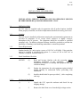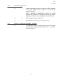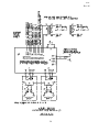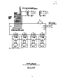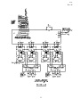
1
Cooper Industries
Crouse-Hinds Division
Crouse-Hinds Airport Lighting Products
1200 Kennedy Road
Windsor, CT 06095
860 683-4300
Fax 860 683-4354
Title:
DOCUMENT 9131
December 5, 2006
Revision M
INSTRUCTION MANUAL
L-847 RUNWAY CIRCUIT SELECTOR SWITCH
Series –84700
COPYRIGHT © 2006 Cooper Technologies Company
FOR PARTS AND SERVICE, CALL 860-683-4300
9131
Rev. M
REV.
DESCRIPTION
LTR.
CHK.
APV
A
Added Figure 6-3, -4, -11 (Pg. 39); Pg. 37 deleted S2 switch; Pg.
24 & 25, 6.3, 6.4 & 6.11, added figure for remote connections &
deleted info that was present for remote connections; Pg. 25, 6.9,
added info on removing tagged wire
A92037
PG
3/6/92
JAS
3/6/92
B
Added ‘Figures & Tables’ to table of contents; corrected para
3.1.1 page 6; added to para 3.1.4 page 8; added Figure 3C
A92069
C
Revised Table of Contents, Figures & Table Page numbers on vi
and vii to agree after inclusion of Figure 3C per Rev. B
A94215
D
Pages 16, 17, 28, 29, 30, 31, 34, 37 and 39, moved K1
connection from J1-2 to J1-3.
Revised origin & destination in para. 3.1.3.2.3, deleted note
referencing connection as option same para., added page 7A
A94431
A96465
E
F
G
H
J
K
L
M
1) On fig.’s 5-1 & 6-9A, label were 1.25A, Fig. 5-2 label was
2.50A, Fig.’s 6-7F,6-5B, 6-2B & 4-1B, F1 was 2.50A, Fig.’s 41A, 6-2A, 6-5A, 6-9B & 6-7C, F1 was 1.25A.
1) Pg’s 9, 10, 21, 22, 32, 35 & 38, revised Cooper logo; 2) Pg.
38, revised S-1 label to current label; 3) Pg. 39, revised labeling
of TB1 label to accurately represent option -9 function; 4) Pg.
40, added 3rd. view of remote control connections for option -9
1) On page 21, 22 & 38 changed picture of K2 relay to latest
design; 2) On page 23 & 24, item 9 P/N was 30845; 3) On page
23, item 12 P/N was 46-192-5X/D-5 and on page 24 item 12 P/N
was 46-192-5X/D-3; 4) On page 39, added #12 terminal note
In Para. 3.1.3.2.4 & .5, #12AWG was #8AWG
Revised Parts Lists Item 9 was 32407, Relay Assy and added
Items 19 & 20. Updated Figures 5-1, 5-2 and 6-9A to show new
32797 K2 Relay Assy and added Figure 5-1A.
Added Options 14 & 15 to Table 1-1, Figures 5-1, 5-2, 6-2A, and
6-2B, and Section 6
Title pg, revised copyright; Table of Contents, deleted Fig 6-7A
through F; Table 1-1, 150/5345-5B was -5A & option -7 was
Digital Ammeter for Each Circuit (Indoor Use Only); revised Fig
5-1, 5-1A & 5-2 to show latest K2 configuration & mtg plate;
Table 5-1 & 5-2, item 8 C-H P/N was 30846, item 9 C-H P/N
was 32797 & item 19 C-H P/N was 32847; 6.7, discontinued this
option; deleted Fig 6-7A through 6-7F; Fig 6-9A, revised K2
config & mtg plate
ii
A97423
JAS
4/15/92
7/1/94
PG
DG
11/29/94
JAS
9/18/96
7/24/97
JAS
A97516
11/3/97
JAS
A200221
8/7/00
JAS
A202043
A203063
2/25/02
GFR
3/04/04
GFR
3/9/05
GFR
12/5/06
PG
A204292
A206442
9131
Rev. M
LIMITED PRODUCT WARRANTY
THE FOLLOWING WARRANTY IS EXCLUSIVE AND IN LIEU OF ALL OTHER
WARRANTIES, WHETHER EXPRESS, IMPLIED OR STATUTORY, INCLUDING, BUT
NOT BY WAY OF LIMITATION, ANY WARRANTY OF MERCHANTABILITY OR
FITNESS FOR ANY PARTICULAR PURPOSE.
Crouse-Hinds Airport Lighting Products (the “Company”) warrants to each original Buyer of
Products manufactured by the Company that such Products are, at the time of delivery to the Buyer,
free of material and workmanship defects, provided that no warranty is made with respect to:
(a)
any Product which has been repaired or altered in such a way, in Company's
judgment, as to affect the Product adversely;
(b)
any Product which has, in Company's judgment, been subject to negligence,
accident or improper storage;
(c)
any Product which has not been operated and maintained in accordance with
normal practice and in conformity with recommendations and published
specification of Company; and,
(d)
any Products, component parts or accessories manufactured by others but
supplied by Company (any claims should be submitted directly to the
manufacturer thereof).
Crouse-Hinds Airport Lighting Products’ obligation under this warranty is limited to use reasonable
efforts to repair or, at its option, replace, during normal business hours at any authorized service
facility of Company, any Products which in its judgment proved not to be as warranted within the
applicable warranty period. All costs of transportation of Products claimed not to be as warranted
and of repaired or replacement Products to or from such service facility shall be borne by Purchaser.
Company may require the return of any Product claimed not to be as warranted to one of its
facilities as designed by Company, transportation prepaid by Purchaser, to establish a claim under
this warranty. The cost of labor for installing a repaired or replacement product shall be borne by
Purchaser. Replacement parts provided warranty period of the Products upon which they are
installed to the same extent as if such parts were original components thereof. Warranty services
provided under the Agreement do not assure uninterrupted operations of Products; Company does
not assume any liability for damages caused by any delays involving warranty service. The warranty
period for the Products is 24 months from date of shipment or 12 months from date of first use
whichever occurs first.
iii
9131
Rev. M
SAFETY NOTICES
This equipment is normally used or connected to circuits that may employ voltages, which are
dangerous and may be fatal if accidentally contacted by operating or maintenance personnel.
Extreme caution should be exercised when working with this equipment. While practical safety
precautions have been incorporated in this equipment, the following rules must be strictly observed:
KEEP AWAY FROM LIVE CIRCUITS
Operating and maintenance personnel must at all times observe all safety regulations. DO NOT
PERFORM MAINTENANCE ON INTERNAL COMPONENTS OR RE-LAMP WITH
POWER ON.
RESUSCITATION
Maintenance personnel should familiarize themselves with the technique for resuscitation found in
widely published manuals of first aid instructions.
iv
9131
Rev. M
TABLE OF CONTENTS
PAGE
Title Page...............................................................................................................................................i
Revisions..............................................................................................................................................ii
Limited Product Warranty..................................................................................................................iii
Safety Notices......................................................................................................................................iv
Table of Contents................................................................................................................................v
Figures & Tables................................................................................................................................vi
SECTION 1: GENERAL INFORMATION
1.1
1.2
1.3
Introduction..............................................................................................................................1
Equipment Description.............................................................................................................1
Installation Requirements.........................................................................................................2
SECTION 2: TECHNICAL DESCRIPTION
2.1
Theory of Operation.................................................................................................................4
SECTION 3: INSTALLATION AND OPERATION
3.1
3.2
Installation................................................................................................................................6
Operation................................................................................................................................12
SECTION 4: MAINTENANCE
4.1
4.2
4.3
Periodic Maintenance.............................................................................................................14
Corrective Maintenance..........................................................................................................14
Troubleshooting Chart............................................................................................................15
SECTION 5: PARTS LIST
5.1
5.2
5.3
Scope......................................................................................................................................20
Arrangement................. .........................................................................................................20
Reference Designation............................................................................................................20
SECTION 6: OPTIONS
6.1
6.2
6.3
6.4
6.5
6.6
6.7
6.8
6.9
6.10
6.11
6.12
6.13
6.14
6.15
Scope.......................................................................................................................................25
Option -2.................................................................................................................................25
Option -3.................................................................................................................................25
Option -4.................................................................................................................................25
Option -5.................................................................................................................................25
Option -6.................................................................................................................................25
Option -7.................................................................................................................................25
Option -8.................................................................................................................................25
Option -9.................................................................................................................................26
Option -10...............................................................................................................................26
Option -11...............................................................................................................................26
Option -12...............................................................................................................................26
Option -13...............................................................................................................................26
Option -14...............................................................................................................................26
Option -15...............................................................................................................................26
v
9131
Rev. M
FIGURES
PAGE
Figure 2-1
Typical CSC Timing Diagram....................................................................................5
Figure 3A
84700-1 or -2 Suggested Conduit Entrances..............................................................9
Figure 3B
84700-3 or -4 Suggested Conduit Entrances............................................................10
Figure 3C
Printed Circuit Board 31955.....................................................................................11
Figure 4-1A Wiring Diagram 84700-2..........................................................................................16
Figure 4-1B Wiring Diagram 84700-4..........................................................................................17
Figure 5-1
84700-1 or -2 Components.......................................................................................21
Figure 5-1A View B....................................................................................…………………….21a
Figure 5-2
84700-3 or -4 Components.......................................................................................22
Figure 6-2A Wiring Diagram 84700-2-2.......................................................................................28
Figure 6-2B Wiring Diagram 84700-4-2.......................................................................................29
Figure 6-5A Wiring Diagram 84700-5 or -6..................................................................................30
Figure 6-5B Wiring Diagram 84700-4-5 or -6...............................................................................31
Figure 6-9A 84700-2-9...................................................................................................................32
Figure 6-9B Wiring Diagram 84700-2-9........................................................................................33
Figure 6-3,-4,-11
Internal & Remote Control Connections........................................................34
TABLES
PAGE
Table 1-1
Table 4-2
Table 5-1
Table 5-2
Table 6-1
84700 Part Numbers....................................................................................................3
Troubleshooting Procedure........................................................................................18
Parts List, 84700-1 or -2............................................................................................23
Parts List, 84700-3 or -4............................................................................................24
Circuit Card Part Number Variations...................................................................... ..27
vi
9131
Rev. M
SECTION 1
GENERAL INFORMATION
1.1
INTRODUCTION
1.1.1
Purpose
This instruction book provides field support data and information for the FAA Type
L-847 Runway Circuit Selector Switches manufactured by Crouse-Hinds Airport
Lighting Products, Windsor, CT 06095. The equipment is herein after referred to as
a CSC.
1.1.2
Applicability
This instruction book applies only to that hardware bearing the part number series
84700. Instructions for standard options are provided in Section 6 of this document.
Refer to Table 1-1 for complete part number information.
1.2
EQUIPMENT DESCRIPTION
1.2.1
Function
The FAA Type L-847 CSC is a power switching cabinet specifically designed for
connection to the output of an FAA Type L-828 Airport Lighting Constant Current
Regulator (CCR). It is capable of switching one or more series lighting circuits
either locally or from a remote location, without affecting CCR operation.
1.2.2
Features
The CSC is designed to accommodate lighting loads of up to 70KW at 20 amps and
30KW at 6.6 amps. Standard models are equipped with from one to four circuit
capability in one NEMA 1 enclosure. Any combination of load circuits may be
energized simultaneously. Modular construction has been utilized to provide ease of
maintenance. A clear dead front cover allows safe inspection of high voltage
components without the need to de-energize the lighting system.
1.2.3
Options
A number of factory installed options are available. These options, listed in Table 11, enable the customer to configure the CSC for a variety of specific applications. It
is recommended that the customer contact Crouse-Hinds to verify the specific
options required for an application prior to order submittal. Option -1 is installed on
all units. See Section 3.1.4.
1.2.4
Specifications
The following specification data applies to a standard model 84700 series CSC
without options.
1
9131
Rev. M
1.2.4.1
FAA Classification
Type:
Class:
Rating:
1.2.4.2
1.2.4.3
L-847-1, -2, -3, -4
A (for Class B, order Option -10 or -13)
1 and 2 (Dual Rating)
Electrical Characteristics
Primary Power:
L-847-1, -2: 120 VAC, 1.2A, 50/60Hz
L-847-3, -4: 120 VAC, 2.4A, 50/60Hz
Regulator Rating:
All Models: Up to 20 amps at up to 5000 volts, continuous.
Relay contacts rated for 5000 operations.
Physical Characteristics
Dimensional:
L-847-1, -2: 24" H x 21" W x 9" D, 67 lbs.
L-847-3, -4: 24" H x 30" W x 9" D, 103 lbs.
Mechanical:
All models supplied in a NEMA 1 enclosure painted blue. All
high voltage components protected by a clear dead front cover.
Environmental:
Temperature: -55° to +55°C
(-67° to +131°F)
Altitude:
0 to 10,000 ft.
Humidity:
1.3
Up to 100 percent
INSTALLATION REQUIREMENTS
The CSC is shipped from the factory complete and ready for installation. The agency
responsible for installation must supply all necessary connectors, wire and conduit.
Markings are provided on the enclosure at recommended conduit entry points. The
enclosure may be surface mounted on a wall or conduit mounted on a suitable
concrete base.
2
9131
Rev. M
TABLE 1-1
84700 PART NUMBERS
UP TO THREE OPTIONS
BASIC NO.....-.....NUMBER OF CIRCUITS.....-.....OPT A.....-.....OPT B.....-.....OPT B
84700
(1 through 4)
(Three Options from the selection chart)
•
The standard equipment includes the following:
•
NEMA 1 Cabinet
•
120 VAC, 50/60 Hz primary power to be supplied by customer
•
Internal 120 VAC remote control power
•
Handles both 6.6 or 20 amp circuits with any standard regulator
•
Meets FAA 150/5345-5B requirements
•
Unit provides simultaneous switching (i.e., A or B, or A + B)
OPTION SELECTION CHART
OPTION NO.
DESCRIPTION
-1
De-Energized Switching. Included in all units
-2
Primary Power 220 to 240 VAC, 50/60Hz
-3
Remote Control 48 VDC (External 48 VDC)
-4
Remote Control 120 VAC, 50/60Hz (External)
-5
Remote Back Indication, 6.6 Amp Circuits (ON-OFF)
-6
Remote Back Indication, 20 Amp Circuits (ON-OFF)
-7
Discontinued
-8
Exclusive Circuit Selection (A or B) Only
-9
Back-Up Regulator Switching (available on L-847-2 only)
-10
NEMA 4 Cabinet
-11
Remote Control 24 VDC (External 24 VDC)
-12
Cabinet Door Interlock Switch
-13
NEMA 4X Cabinet
-14
Without Cabinet
-15
Primary Power 480 VAC, 50/60Hz
3
9131
Rev. M
SECTION 2
TECHNICAL DESCRIPTION
2.1
THEORY OF OPERATION
The operational discussion presented herein pertains to standard model CSC units.
Equipment supplied with options may deviate somewhat from the exact operational
description presented, but the basic operating principles are identical for all
equipment configurations.
2.1.1
Local Control
The CSC control circuits operate from the 120 VAC primary power source and
energize the relay coils in the high voltage circuit to supply power to the lighting
circuit selected. When switch, remote-off-local, is selected to LOCAL, switches S1
and S2 (S1 through S4) are active. When any of these switches is set to ON, a signal
is applied to the timing circuits located on the circuit card assembly. The timing
circuit, in turn, supplies power immediately to the coil of the respective double pole
relay in the high voltage section. After a brief delay, less than one second, the timing
circuit supplies power to the coil of the associated single pole shorting relay in the
high voltage section, thus energizing the lighting circuit. (Note: Due to the
characteristics of Type L-828 Regulators, the other lighting loads may dim
momentarily. This is normal.) To de-energize a lighting circuit, the respective
control switch is selected to OFF. This action immediately de-energizes the single
pole shorting relay, which places a short across the lighting circuit. After a brief
delay, the timing circuit removes power from the coil of the double-pole isolating
relay, which opens to isolate the lighting circuit from the regulator. The timing
diagram in Figure 2-1 may be helpful in understanding the switching sequence.
De-energized switching (Option -1) is installed on all units. This turns the regulator
off prior to switching the circuits and turns the regulator back on after the circuits
have been switched. See Sections 3.1.3.2 and 3.1.4 for more detail.
2.1.2
Remote Operation
The CSC, when operated remotely, functions exactly the same as when under local
control, except that switches S1 and S2 (S1 through S4) are not active. Remote
control power is normally derived internal to the CSC. However, external power
sources may be used if the proper option is specified.
2.1.3
CCR Interlock
An interlock switch is provided for the high voltage section of the CSC. This switch
should be connected in series with the control circuit of the CCR to provide for
immediate shutdown of the CCR in the event that the dead front cover of the CSC is
removed. Normally, however, the CCR or CCRs should be de-energized prior to
removal of the dead front cover
4
9131
Rev. M
5
9131
Rev. M
SECTION 3
INSTALLATION AND OPERATION
WARNING
INSTALLATION, SERVICE, MAINTENANCE OR OPERATION SHOULD
BE PERFORMED BY QUALIFIED PERSONNEL ONLY.
3.1
INSTALLATION
All CSC units are supplied ready for operation with all ordered options installed.
When properly connected, no electrical adjustments should be necessary prior to use.
3.1.1
Location
The CSC may be installed in all locations meeting the environmental requirements as
specified in paragraph 1.2.4.3 except where explosive or highly corrosive
atmospheres may be present. The equipment should be accessible to qualified
personnel only. In addition, adequate drainage should be provided to preclude the
possibility of standing water hindering maintenance or normal operations.
3.1.2
Power Requirements
Standard model CSC units require a source of 120 VAC at 50/60Hz. If the particular
unit to be installed is equipped with option -2, a source of 220 to 240 VAC at
50/60Hz is required. Refer to Table 1-1.
3.1.3
Detail Installation Checklist
NOTICE:
3.1.3.1
(1)
Read and become familiar with this procedure before
attempting installation of this equipment.
Improper
installation procedures can damage this equipment and may
void the warranty!
(2)
Further, the instructions for each equipment option included
should similarly be understood before proceeding with
installation.
(3)
Installer should initial in space provided ( ) after completing
each step.
Mechanical Installation
( )
1.
Unpack the CSC, open the enclosure and check for any
shipping damage.
( )
2.
Remove the dead front cover from the high voltage section.
6
9131
Rev. M
3.1.3.1
3.1.3.2
Mechanical Installation Cont'd
( )
3.
Remove the electrical assembly from the enclosure by
loosening and removing the mounting hardware from the
four corners of the base plate panel.
( )
4.
The electrical assembly can now be placed in the shipping
carton for protection.
( )
5.
Proceed to mount the empty enclosure in the desired fashion.
Recommended conduit hole locations are shown on Figure 3.
( )
6.
Remove all dirt and foreign material from the enclosure, then
re-install the electrical assembly in the enclosure after
completing the mounting and conduit connector installation.
Electrical Wiring
( )
1.
Connect the ground conductor to the ground lug located in
the lower left hand corner of the base plate.
( )
2.
Connect the remote control leads to 31955 TB1 terminals as
indicated.
L - 120 VAC hot lead (Input for Option -2 is
LN - 120 VAC Neutral to "H" terminals on Stepdown Transformer)
CR - Remote Control Common
C1 - Remote Control Circuit 1
C2 - Remote Control Circuit 2
C3 - Remote Control Circuit 3 for 84700-3 & -4
C4 - Remote Control Circuit 4 for 84700-4
Note: 31955 TB1 is removable for ease of installation.
( )
3.
Connect the CCR control power to 31955 TB1 terminals as
indicated:
CC1 - Control Power Feed from Regulator
CC2 - Control Load to Tower
See page 7A.
( )
4.
Connect the output of the CCR to terminals R1 and R2, in
the high voltage section, using the #12 AWG ring terminals
provided.
7
9131
Rev. M
3.1.3.2
Electrical Wiring Cont'd
( )
5.
Connect each lighting load to the respective LOOP terminals
in the high voltage section, using the #12 AWG ring
terminals provided.
NOTE:
BEFORE CONNECTING LOAD TO LOOP
TERMINALS, REMOVE JUMPER FROM ONLY THOSE
TERMINALS THAT LOAD IS BEING CONNECTED TO.
3.1.4
( )
6.
Make any option related connections.
( )
7.
Re-install the dead front cover and fasten securely.
Option -1, De-Energized Switching, Disabling
( )
1.
To disable de-energized switching feature, move E2 spring
shunt on 31955 circuit assembly from E2-2/E2-3 to E2-1/E22, refer to Figure 3C.
8
9131
Rev. M
9
9131
Rev. M
10
9131
Rev. M
11
9131
Rev. M
3.2
OPERATION
3.2.1
Initial Checkout
This checkout is divided into two sections. In the first section, all control functions
are checked. In the second, the high voltage functions are checked. If the CSC fails
to perform properly at any step of this procedure, consult the troubleshooting guide
in Section 4.
3.2.1.1
3.2.1.2
Control Functions
( )
1.
Set all CSC switches to the OFF position.
( )
2.
Apply Primary Power to the CSC.
( )
3.
Set switch to the local operation position and verify visually
that none of the high voltage relays pull-in.
( )
4.
Set switch S1 to ON and verify visually that the LOOP 1
high voltage relays energize. (Refer to Section 2.1.1 for
operational details).
( )
5.
Set switch S1 to OFF and verify visually that the LOOP 1
high voltage relays de-energize.
( )
6.
Repeat steps 4 and 5 for the remaining switches and LOOPs.
( )
7.
Verify proper remote control operation by setting to the
remote position and exercising the remote control circuit.
High Voltage Functions
( )
1.
Turn on the CCR to the lowest intensity step. Verify it does
not trip-out on open circuit.
( )
2.
Set each switch on the CSC to the ON position and verify
that the associated lighting circuit is energized. Some
contact arcing is normal during switching.
( )
3.
Checkout of the dead front interlock should be accomplished
as follows:
A.
Turn off, lock and tag the CCR.
B.
Remove primary power from the CSC.
C.
Remote the dead front cover and close the CSC
cabinet door.
12
9131
Rev. M
3.2.1.2
3.2.2
High Voltage Functions Cont'd
D.
Attempt to turn on the CCR. Verify it does not turn
on.
E.
After repeating Step A above, re-install the dead front
cover on the CSC.
F.
Restore power to all circuits.
Normal Operation
In most cases, the CSC will be operated from a remote location. To affect this mode,
set to remote and close the cabinet door. No other adjustments are necessary. To
operate the CSC locally, set for local operation and select the desired lighting circuit
by setting the associated local switch to ON. It is strongly recommended that the
CSC cabinet door be closed securely when the equipment is unattended to preclude
unauthorized operation.
13
9131
Rev. M
SECTION 4
MAINTENANCE
WARNING
INSTALLATION, SERVICE, MAINTENANCE OR OPERATION SHOULD
BE PERFORMED BY QUALIFIED PERSONNEL ONLY.
4.1
PERIODIC MAINTENANCE
The CSC should be inspected periodically as shown below:
4.2
INTERVAL
ACTION
1 month
(A)
Visually inspect high voltage relays through clear
dead front cover.
3 months
(A)
Perform Control Functions checkout per Section
3.2.1.1 to verify proper operation.
6 months
(A)
Isolate the CSC and CCR from all sources of
electrical power.
(B)
Check all wiring connections for loose or missing
screws. Check terminal blocks and component
connections.
(C)
Check for broken or damaged wires and components.
(D)
Remove dust build up.
(E)
Inspect housing for rust or chipped paint. Clean and
touch up with paint as required.
(F)
Re-install all covers and restore primary power to the
CSC and CCR.
CORRECTIVE MAINTENANCE
In general, corrective maintenance is performed by the replacement of parts rather
than repair when they cease to function properly. The use of easily removable subassemblies facilitates repair. The removal and replacement procedure should be
obvious to qualified maintenance personnel.
14
9131
Rev. M
4.2
CORRECTIVE MAINTENANCE CONT'D
WARNING
VOLTAGES IN EXCESS OF 1000 VOLTS ARE PRESENT WHEN THE
REGULATOR IS OPERATING.
DO NOT ATTEMPT REPAIR OR
SERVICING WITHOUT FIRST REMOVING POWER FROM THE
REGULATOR. THE USE OF LOCK-OUT DEVICES IS RECOMMENDED
FOR INSTALLATIONS WHERE THE POWER DISTRIBUTION PANEL IS
NOT READILY VISIBLE FROM THE REGULATOR OR CSC LOCATION.
Caution should be exercised if removal of Circuit Card Assembly becomes necessary
as the board is easily damaged by improper removal and handling, either of which
would void the warranty. Particular areas of concern are:
4.3
(A)
Power must be removed from the CSC before attempting to
disconnect or re-connect the connector plugs from the board.
(B)
The circuit card is held in place by five screws and by washer and nuts
on switch actuators. All screws, nuts and washers must be replaced
after the circuit card has been re-installed and before plugs are reconnected to the board. Failure to do so will probably result in
permanent or intermittent circuit board damage.
TROUBLESHOOTING CHART
The following Troubleshooting Procedure, Table 4-2, is provided as a guideline to
assist qualified airport maintenance personnel in locating and correcting any
malfunctions when they occur. See Figure 4-1, CSC Schematic, for reference during
troubleshooting.
15
9131
Rev. M
16
9131
Rev. M
17
9131
Rev. M
TABLE 4-2
TROUBLESHOOTING PROCEDURE
PROBLEM
CSC does not
operate in remote
(all circuits)
One or two circuits
of CSC do not
operate in local or
remote
Regulator trips off
when one or more
circuits are
activated
POSSIBLE CAUSE
Power source not
energized
TEST
Verify voltage is
present at TB1-L, LN
CORRECTIVE ACTION
Restore power
Blown fuse
Check F1
Replace fuse
Broken wire
Check wiring harness
Repair or replace harness
assy
Broken wire
Check wiring harness
Repair or replace harness
assy
Loose or defective
H.V. relay module
Check connector
Re-seat connector on
Timing Circuit Card
Check relay control
harness
Repair or replace relay
harness
Miswired lighting
-----
Check all wiring
Defective relay or
open lighting circuit
Disconnect wires to
R1 & R2 using an
ohmmeter, determine
fault location
Repair lighting circuit or
replace relay module or
faulty relay
Regulator current
falls when light
circuit is activated
regulator capacity is
insufficient
Calculate total load
requirements
Use a larger regulator
CSC does not
operate in remote
Remote control wires
connected incorrectly
or broken
Check remote
connections
Repair remote control
equipment
Defective timing
circuit
------
18
If remote control signals are
correct, the problem is
probably due to a defective
timing circuit card.
Observe all precautions of
para. 4.2 when replacing
the timing circuit card
9131
Rev. M
PROBLEM
No distinct delay
between high voltage
relay actions
High voltage
POSSIBLE
CAUSE
Defective timing
circuit card
TEST
CORRECTIVE ACTION
------
Replace the timing circuit
card. Observe all precautions
of para. 4.2 when replacing
the timing card
Relay module at
end of rated life
------
Replace the high voltage
relay module or relay
19
9131
Rev. M
SECTION 5
PARTS LIST
5.1
SCOPE
The following Parts List provides ordering data for all repairable or replaceable
components and assemblies.
5.1.1
List of Figures
Figure 5-1
Component Identification, 84700-1 or -2
Figure 5-2 Component Identification, 84700-3 or -4
5.1.2
5.2
List of Tables
Table 5-1
Circuit Selector Parts List, 84700-1 or -2
Table 5-2
Circuit Selector Parts List, 84700-3 or -4
ARRANGEMENT
The Figures and Tables in this section are arranged to show each replaceable part or
assembly. The parts are identified in each Figure by Index Number. The Index
Number also appears in the corresponding Parts List, which also provides the part
number and description.
5.3
REFERENCE DESIGNATION
A reference designation number is assigned to each electrical part contained in the
circuit selector. These reference designations are shown on the wiring diagrams,
Figure 4-1 and in the Circuit Selector Parts List, Table 5-1 and 5-2.
20
9131
Rev. M
21
9131
Rev. M
21a
9131
Rev. M
22
9131
Rev. M
TABLE 5-1
PARTS LIST, 84700-1 OR -2
ITEM
NO
REFERENCE
DESIGNATION
QUANTITY DESCRIPTION
-1
-2
CROUSE
HINDS PART
NUMBER
31525
1
1
1
Cabinet
2
1
1
Base Plate
30858
3
1
1
Low Voltage Panel
31973
4
1
1
Circuit Card assembly
31955-1
5
1
2
Relay Module Assembly
30848-1
6
1
1
Dead Front Plate
30832
7
1
1
Dead Front Bracket
30828
*8
K1
1
2
Relay, High Voltage, SPNC
34197
*9
K2
1
2
Assembly, Vacuum Relay,
L-847
34196
10
1
1
Switch Label
31981
11
1
1
Interlock Switch
12
-
1
Jumper Wire
46-245-5X/D-5
13
1
1
Ground Stud
10053-184
14
10047-1616
Not Used
**15
1
1
Fuse, 2.0A
16
1
1
Interlock Harness
31985
*17
1
2
Relay Harness
30853
*19
1
2
Assembly,L-847 Relay Interface
34195
*20
1
2
Harness, L-847 Relay Interface
32849
18
10047-1590
NOT USED
* = Part of Item 5 Assembly
** = Part of Item 4
23
9131
Rev. M
TABLE 5-2
PARTS LIST, 84700-3 OR -4
ITEM
NO
REFERENCE
DESIGNATION
QUANTITY DESCRIPTION
-3
-4
CROUSE
HINDS PART
NUMBER
31530
1
1
1
Cabinet
2
1
1
Base Plate
30859
3
1
1
Low Voltage Panel
31974
4
1
1
Circuit Card assembly
31955-2
5
2
2
Relay Module Assembly
30848-1
6
1
1
Dead Front Plate
30833
7
1
1
Dead Front Bracket
30829
*8
K1
3
4
Relay, High Voltage, SPNC
34197
*9
K2
3
4
Assembly, Vacuum Relay,
L-847
34196
10
1
1
Switch Label
31975
11
1
1
Interlock Switch
12
2
3
Jumper Wire
46-245-5X/D-4
13
1
1
Ground Stud
10053-184
14
1
2
Relay Module Assembly
**15
1
1
Fuse, 3.0A
16
1
1
Interlock Harness
31985
*17
2
2
Relay Harness (Item 5 only)
30853
*18
1
2
Relay Harness (Item 14 only)
30853-1
*19
3
4
Assembly,L-847 Relay Interface
34195
*20
3
4
Harness, L-847 Relay Interface
32849
* = Part of Item 5 or 14 Assembly
** = Part of Item 4
24
10047-1616
30848-4
10047-1591
9131
Rev. M
SECTION 6
OPTIONS
6.1
SCOPE
The following listing provides parts ordering data and customer installation data.
6.2
OPTION -2
The part number for the 220VAC transformer is 10047-1444. Customer primary
input connections are at points H1 and H4 on the transformer; see Figures 6-2A and
6-2B. See Figure 5-1 or 5-2 for transformer location.
6.3
Option -3
Item 4 circuit card, see Figure 5-1 or 5-2 for location, changes with Option -3. See
Table 6-1 for circuit card part number variations. See Figure 6-3,-4,-11 for external
remote control connections.
6.4
Option -4
Item 4 circuit card, see Figure 5-1 or 5-2 for location, changes with Option -4. See
Table 6-1 for circuit card part number variations. See Figure 6-3,-4,-11 for external
remote control connections.
6.5
Option -5
The part number for the current sensing circuit card is 31978-1 for 1 loop sensing
(84700-1 or -3, 1 required) and 31978-2 for 2 loop sensing (84700-2 or -4; -4
requires 2 cards). Item 5 relay module P/N is 30848-3. Item 14 relay module P/N is
30848-6. See Figure 5-1 or 5-2 for parts locations. See Figure 6-5A or 6-5-B for
wiring diagram.
6.6
Option -6
Same as Option -5, except Item 5 P/N is 30848-2 and Item 14 P/N is 30848-5.
6.7
Option -7
Discontinued.
6.8
Option -8
Item 4 circuit card, see Figure 5-1 or 5-2 for location, changes with option -8. See
Table 6-1 for circuit card part number variations.
25
9131
Rev. M
6.9
Option -9
Item 11 P/N is 10047-1878. Item 12 P/N is 46-192-5X/D-8. The part number for the
interlock switch harness is 31985-1. Item 5 P/N is the same as for standard 84700-2
module, except option -9 labeling required and, if present, remove lead with tag
"THIS JUMPER TO BE REMOVED ONLY WHEN CONNECTING LOAD TO
THESE TERMINALS". See Figure 6-9A for parts location. See Figure 6-9B for
wiring diagram.
6.10
Option -10
Cabinet P/N is 30834 for 84700-1 or -2 and 30835 for 84700-3 or -4.
6.11
Option -11
Item 4 circuit card, see Figure 5-1 or 5-2 for location, changes with Option -11. See
Table 6-1 for circuit card part number variations. See Figure 6-3,-4,-11 for external
remote control connections.
6.12
Option -12
Item 14 P/N is 10047-2276 (except when used with Option -9; use Option -9 Item
14). The actuator extender P/N is 10037-573. Item 10 P/N for 84700-1 or -2 is
31986 and 31987 for 84700-3 or -4. See Figure 5-1 or 5-2 for parts location.
6.13
Option -13
Cabinet P/N is 30834-1 for 84700-1 or -2 and 30835-1 for 84700-3 or -4.
6.14
OPTION -14
Circuit Selector Switch without the Cabinet.
6.15
OPTION -15
The part number for the 480VAC transformer is 10047-1444. Customer primary
input connections are at points H1 and H4 on the transformer; see Figures 6-2A and
6-2B. See Figure 5-1 or 5-2 for transformer location.
26
9131
Rev. M
TABLE 6-1
PART NUMBER
USED ON
31955-1
84700-1 or -2
31955-2
84700-3 or -4
31955-3
84700-2-9
31955-4
84700-1 or -2 w/Opt. -8
31955-5
84700-3 or -4 w/Opt. -8
31955-6
84700-1 or -2 w/Opt. -3
31955-7
84700-3 or -4 w/Opt. -3
31955-8
84700-2-3, -9
31955-9
84700-1 or -2 w/Opts. -3 & -8
31955-10
84700-3 or -3 w/Opts. -3 & -8
31955-11
84700-1 or -2 w/Opt. -11
31955-12
84700-3 or -4 w/Opt. -11
31955-13
84700-2-9, -11
31955-14
84700-1 or -2 w/Opts. -8 & -11
31955-15
84700-3 or -4 w/Opts. -8 & -11
31955-1-4
84700-1 or -2 w/Opt. -4
31955-2-4
84700-3 or -4 w/Opt. -4
31955-3-4
84700-2 w/Opts. -4 & -9
31955-4-4
84700-1 or -2 w/Opts. -4 & -8
31955-5-4
84700-3 or -4 w/Opts. -4 & -8
27
9131
Rev. M
28
9131
Rev. M
29
9131
Rev. M
30
9131
Rev. M
31
9131
Rev. M
32
9131
Rev. M
33
9131
Rev. M
34