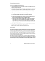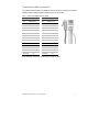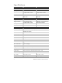
1
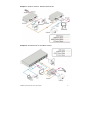
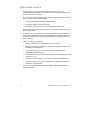
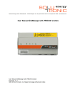
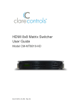
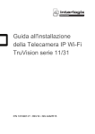
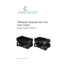
HDBaseT Extender Set 70m
User Guide
Model CM-BT10-TXRX70
Doc ID 2015-04-350 • Rev 04
Copyright
© 24APR15 Clare Controls, Inc. All rights reserved.
This document may not be copied in whole or in part or otherwise
reproduced without prior written consent from Clare Controls, Inc.,
except where specifically permitted under US and international
copyright law.
Trademarks and
patents
HDBaseT Extender Set 70m, Model CM-BT10-TXRX70 name is a
trademark of Clare Controls, Inc.
Other trade names used in this document may be trademarks or
registered trademarks of the manufacturers or vendors of the
respective products.
Manufacturer
Version
Contact information
Clare Controls, Inc.
7519 Pennsylvania Ave., Suite 104, Sarasota, FL 34243, USA
This document applies to HDBaseT Extender Set 70m User Guide,
Model CM-BT10-TXRX70.
For contact information, see www.clarecontrols.com.
Doc ID 2015-04-350 • Rev 04
Content
Limitation of liability...ii Introduction...1 Features...1 Package contents...1 Product appearance...2 System connection...4 Usage precautions...4 Application examples...4 Connection procedure...6 Application...6 Twisted pair cable connection...7 Specifications...8 Panel drawings...9 Troubleshooting and maintenance...10 Safety operation...11 After-sales service...12 HDBaseT Extender Set 70m User Guide
i
Limitation of liability
To the maximum extent permitted by applicable law, in no event will Clare
Controls, Inc. be liable for any lost profits or business opportunities, loss of use,
business interruption, loss of data, or any other indirect, special, incidental, or
consequential damages under any theory of liability, whether based in contract,
tort, negligence, product liability, or otherwise. Because some jurisdictions do not
allow the exclusion or limitation of liability for consequential or incidental damages
the preceding limitation may not apply to you. In any event the total liability of
Clare Controls, Inc. shall not exceed the purchase price of the product. The
foregoing limitation will apply to the maximum extent permitted by applicable law,
regardless of whether Clare Controls, Inc. has been advised of the possibility of
such damages and regardless of whether any remedy fails of its essential
purpose.
Installation in accordance with this manual, applicable codes, and the instructions
of the authority having jurisdiction is mandatory.
While every precaution has been taken during the preparation of this manual to
ensure the accuracy of its contents, Clare Controls, Inc. assumes no responsibility
for errors or omissions.
ii
HDBaseT Extender Set 70m User Guide
Introduction
The extender set consists of a transmitter and receiver pair. HDMI signals are input into
the transmitter and HDBaseT technology is used to transmit the signals to the receiver
up to 230 ft. (70 m) via a Cat5e/Cat6 cable. The receiver then outputs the HDMI signal.
Bi-directional IR and RS232 are also transmitted across the Cat5e/Cat6 cable. The
extender set supports CEC, bi-directional RS232 and IR control, and PoC, which can
be used to power the receiver via the Cat5e/Cat6 cable. This eliminates the need for
power at the receiver end.
Features
•
Supports full HD: Delivers high-resolution image (1080p at 60 Hz, 3D,
4K × 2K at 30 Hz)
•
Maximum transmission distance is 230 ft. (70 m) over single a CAT5e/CAT6 cable,
or 40 meters for 4Kx2K at 30 Hz
•
High bandwidth: 10.2 Gbps
•
HDTV compatible: Uses HDMI 1.4 and is HDCP-2.2 compliant
•
Support PoC (Power Over Cable) and CEC
•
Connects with a displayer to transmit EDID and Hot Plug Detect (HPD) signals
constantly via the CAT5e/Cat6 cable
•
Uses HDBaseT technology for extended capability and reliability
•
Bi-directional RS232/IR control
•
LED indicators show working status to aid in troubleshooting
•
Wall or table mount aluminum enclosure
•
External power supply (100~240 VAC, 50/60 Hz)
Package contents
•
1 x CM-BT10-TX70 HDBaseT transmitter
•
1 x CM-BT10-RX70 HDBaseT receiver
•
1 x 3.5 mm male mono to 3.5 mm male stereo IR adapter cable
•
4 x detachable mounting ears
•
2 x RS232 cables (DB9 to 3-pin connector)
•
8 x screws
•
1 x power adapter (24 VDC)
•
1 x user manual
•
1 x IR emitter
Notes: Ensure all the accessories are included. If not, contact your dealer.
HDBaseT Extender Set 70m User Guide
1
Product appearance
Figure 1: The CM-BT10-TX70 transmitter
(1) IR
IR receiver.
(2) ON
Working status indicator of this device. When the CM-BT10-TX70 is on
and working properly, the green LED blinks.
(3) LINK
HDBaseT link status indicator, green LED. It remains illuminated when
the device has a connection.
(4) IN
The LED remains on when connected with devices that support HDCP
and are working normally. If the devices do not support HDCP, this
green LED blinks.
(5) POWER LED
The red LED illuminates and stays on when power is connected.
(6) HDBT OUT
Connects via a single Cat5e/Cat6 cable to the HDBaseT port on the
CM-BT10-RX70 receiver.
(7) HDMI IN:
Connect to the HDMI source device.
(8) IR IN:
Connects to an IR receiver. The IR signal received from this port will be
transmitted via HDBaseT to the transmitter unit for use at the source
location.
Notes
When using a control system such as Clare Controls, Crestron, or URC,
the 3.5 mm male mono to 3.5 mm male stereo adapter cable (included)
must be used. The male mono end connects to the control system; the
male stereo end connects to the CM-BT10-TX70.
When an IR receiver connects to this port, the front IR port (1) is
unavailable.
(9) IR OUT:
IR signals received by the CM-BT10-RX70 and sent via HDBaseT to the
CM-BT10-TX70 are available for emitter use from this port.
(10) RS232:
RS232 connector. Supports bi-directional RS232 communication.
(11) 24V DC:
Connects to the power supply.
2
HDBaseT Extender Set 70m User Guide
Figure 2: The HDBaseT Extender Set receiver
(1) IR
IR receiver.
(2) ON
Working status indicator of this device. When the CM-BT10-RX70 is on
and working properly, the green LED blinks.
(3) LINK
HDBaseT link status indicator, green LED. Remains illuminated when
there is a connection.
(4) OUT
The LED remains illuminated when connected with devices that support
HDCP, and the HDCP handshake is working normally. If the devices do
not support HDCP, this green LED blinks.
(5) POWER LED
The red LED illuminates and stays illuminated when power is connected.
(6)HDBT IN
Connects via single Cat5e/Cat6 cable to the HDBaseT port in the
CM-BT10-TX70 transmitter or the CM-MT4410-BT-70 matrix switch.
(7) HDMI OUT:
Connect to the HDMI display device.
(8) IR IN:
Connects to an IR receiver. The IR signal received from this port is
transmitted via HDBaseT to the transmitter unit for use at the source
location.
Note: When an IR receiver connects to this port, the front IR port (1) is
unavailable.
(9) IR OUT:
IR signals received by the CM-BT10-TX70 or CM-MT4410-BT-70 and
sent via HDBaseT to the CM-BT10-RX70 are available for emitter use
from this port.
(10) RS232:
RS232 connector. Supports bi-directional RS232 communication.
(11) 24V DC:
Connects to the power supply. Not required when using PoC supplied by
the CM-BT10-TX70 or CM-MT4410-BT-70.
HDBaseT Extender Set 70m User Guide
3
System connection
Usage precautions
•
System should be installed in a clean environment and have proper temperature
and humidity controls.
•
All of the power switches, plugs, sockets, and power cords should be insulated for
safety.
•
All devices should be connected before powering on.
•
The Cat5e/Cat6 terminations for HDBaseT devices should be a straight-thru
TIA/EIA T568B standard.
Application examples
The CM-BT10-RX70 HDBaseT receiver works in conjunction with the CM-BT10-TX70
HDBaseT transmitter or an HDBaseT matrix switch, such as the CM-MT4410-BT-70.
By transmitting signals across reliable Cat5e/Cat6 cables, the video signal can be used
at far greater distances from the source device than would be capable with traditional
HDMI cables. Additionally, control signals can be sent bi-directionally across the same
Cat5e/Cat6 cable. The following figures show you some application examples for the
CM-BT10-TXRX70 extender set and/or the CM-BT10-RX70 receiver.
Note: When using a control system, such as Clare Controls, Crestron, or URC, the
3.5 mm male mono to 3.5 mm male stereo adapter cable (included) must be used. The
male mono end connects to the control system; the male stereo end connects to
CM-BT10-TX70.
4
HDBaseT Extender Set 70m User Guide
Example 1: CM-BT10-TXRX70 - HDBaseT Extender Set
Example 2: CM-MT4410-BT-70 with CM-BT10-RX70
HDBaseT Extender Set 70m User Guide
5
Connection procedure
To connect the HDBaseT Extender Set 70m
1.
Connect HDMI from the source (such as Blu-ray DVD) to the HDMI IN port of the
transmitter using an HDMI cable.
2.
Connect the HDBT OUT port of the transmitter to the HDBT IN port of the receiver
with a single CAT5e/CAT6 cable using TIA/EIA T568B terminations at each end.
3.
Connect the HDMI OUT port of the receiver to an HDMI in port on the display
using an HDMI cable.
4.
When using the bi-directional IR control, do the following.
a. Connect the IR emitter at either end to the IR TX port on either the
CM-BT10-TX70 or the CM-BT10-RX70.
b. When using a powered IR receiver, connect via a 3.5 mm stereo plug to the
IR RX on either the CM-BT10-TX70 or the CM-BT10-RX70.
c. When using a control system to send IR signals, you must use the included
3.5 mm male mono to 3.5 mm male stereo cable adapter. Use a standard
3.5 mm male mono connector from the control system to the male side of the
adapter cable. Plug the 3.5mm male stereo side of the adapter into the IR RX
port on the CM-BT10-TX70.
5.
When using the bi-directional RS232 control, two adapter cables are included for
conversion from the 3-pin connector to DB9 connectors.
Note: Only pins 2,3 & 5 are used on the DB9 (Rx, TX, Gnd).
Application
The CM-BT10-TXRX70 extender pair is useful in any scenario when an HDMI signal
(along with control signals) must be transmitted reliably across greater distances than
is practical using traditional HDMI cables. They may be used in both residential and
commercial applications when centrally locating the source equipment and displaying
HD video in remote locations. The CM-BT10-RX70 can also be used in conjunction
with an HDBaseT matrix switch (such as the CM-MT4410-BT-70) to allow the sharing
of source content across multiple displays.
Note: When connecting your extender set to a TV cable box that transmits HDMI 1.2,
you must use an HDMI 1x2 Splitter (model CM-SP1210-HD) between the TV cable box
and the extender set receiver (model CM-BT10-TX70) The HDMI 1x2 Splitter converts
the HDMI 1.2 signal coming from the cable box to a compliant signal (HDMI 1.3, 1.4).
6
HDBaseT Extender Set 70m User Guide
Twisted pair cable connection
The Cat5e/Cat6 terminations for HDBaseT devices should be a straight thru TIA/EIA
T568B standard. TIA/EIA T568A standard is NOT recommended.
Table 1: T568A and T568B cable standards
TIA/EIA T568A
TIA/EIA T568B
Pin
Cable color
Pin
Cable color
1
green white
1
orange white
2
green
2
orange
3
orange white
3
green white
4
blue
4
blue
5
blue white
5
blue white
6
orange
6
green
7
brown white
7
brown white
8
brown
8
brown
1st Ground
4-5
1st Ground
4-5
2nd Ground
3-6
2nd Ground
1-2
3rd Group
1-2
3rd Group
3-6
4th Group
7-8
4th Group
7-8
Note: RJ45 EZ connectors should not be used at any time.
HDBaseT Extender Set 70m User Guide
7
Specifications
Transmitter (CM-BT10-TX70)
Receiver (CM-BT10-RX70)
Input signal
1 HDMI,1 IR & 1 RS232
1 IR, 1 RJ-45 and 1 RS232
Input connector
HDMI male, 3.5 mm mini jack,
3p captive screw connector
3.5 mm mini jack, RJ-45,
3p captive screw connector
Video signal
HDMI1.4
HDMI1.4
Audio
Digital audio, transmit through
HDMI audio
Digital audio, transmit through
HDMI audio
Output
1 IR, 1 RJ45, and 1 RS232
1 HDMI, 1 IR, 1 RS232
Output connector
3.5 mm mini jack, RJ45,
3p captive screw connector
HDMI male, 3.5 mm mini jack, 3p
captive screw connector
Video signal
HDMI 1.4
HDMI 1.4
Transmission mode
HDBaseT
HDBaseT
Input
Output
General
Resolution range
800 x 600 to 1920 x 1200, 1080p, 3D, 4Kx2K at 30 Hz
Transmission distance
Maximum distance 230 ft. (70 m), 1080p 60 Hz,
4Kx2K at 30 Hz (40 m)
Gain
0 dB to 10 dB at 100 MHz
Differential phase error
±10° at 135 MHz at 100 m
SNR
>70 dB at 100 MHz at 100 m
Bandwidth
10.2 Gbps
Return lost
<-30 dB at 5 KHz
THD
<0.005% at 1 KHz
HDMI standard
Support HDMI 1.4 and HDCP
Min. to max. level
<0.3 to 1.45 Vp-p
Impedance
75Ω
Temperature
-4 to +158ºF (-20 to +70ºC)
Humidity
10% to 90%
Power supply
Input: 100~240 VAC, 50/60 Hz, Output: 24 VDC, 1.25A
Power consumption
9.6 W
Case dimension
(W × H × D)
4.3 × 1.1 × 3.0 in.
(11.0 × 2.8 × 7.7 cm)
4.5 × 1.1 × 3.0 in.
(11.3 × 2.8 × 7.7 cm)
Net weight
1.1 lb. (0.5 Kg)
1.1 lb. (0.5 Kg)
Note: All nominal levels are at ±10%.
8
HDBaseT Extender Set 70m User Guide
Panel drawings
HDBaseT Extender Set 70m User Guide
9
Troubleshooting and maintenance
•
No image on display:
•
Ensure that the display device has been set to the correct input.
•
Ensure that the HDMI cables used for both the source/transmitter and the
receiver/display are properly connected and are working. Test the HDMI
cables directly from a source to display and ensure their operation.
•
Ensure that the Cat5e/Cat6 cable has not been damaged and that it has been
terminated correctly with T568B on both ends. A temporary length of
Cat5e/Cat6 can be used for testing to ensure that the devices are all
compatible and working properly.
•
Ensure proper grounding of the power supply.
•
Known issues with HDMI 1.2 source devices:
•
•
Color loss or poor picture quality:
•
Ensure that the HDMI cables used for both the source and transmitter and the
receiver and display are properly connected and are of good quality. Test the
HDMI cables directly from a source to display and ensure their picture quality.
•
Ensure proper grounding of the power supply.
•
If the static becomes stronger or picture quality becomes worse when
connecting the video connectors, this may be due to improper grounding.
Check the grounding and make sure all the components are properly
grounded to a common ground. Improper grounding may cause damage to
the receiver.
•
IR signal problems:
•
10
Certain cable television STB's are known to have issues with HDBaseT
transmission. This is due to their older compatibility (HDMI 1.2). Please
contact Clare Controls Customer Support for a solution to these issues.
When using a control system such as Clare Controls, Crestron, or URC,
the 3.5 mm male mono to 3.5 mm male stereo adapter cable (included)
must be used. Connect the male mono end to the control system.
Connect the male stereo end to the CM-BT10-TX70.
HDBaseT Extender Set 70m User Guide
Safety operation
To guarantee the reliable operation of the equipment and personal safety, please follow
the procedures listed below.
•
The system must be grounded properly. Do not use two blades plugs. Ensure the
supply voltage is in the correct range of 100~240 VAC, 50/60 Hz.
•
Do not locate the device in a place that is abnormally hot or cold or does not have
proper temperature control and ventilation.
•
The CM-BT10-TX70 and CM-BT10-RX70 generate heat when operating. Their
environment should be well ventilated to prevent damage caused by overheating.
•
Disconnect power in humid weather, or when left unused for long periods.
•
Before making or removing any connections to the device, ensure that the power
supply has been disconnected.
•
Do not attempt to open the enclosure of the equipment. Do not attempt any repairs.
There are no user-serviceable parts inside. Any attempt to open the equipment will
result in a complete void of any warranty and may result in serious injury or death.
•
Do not splash any chemical substances or liquids on or around the equipment.
HDBaseT Extender Set 70m User Guide
11
After-sales service
•
If there appears to be problems when using the device(s), refer to the
“Troubleshooting and maintenance” section in this manual. Return shipping costs
are not covered by this warranty.
•
You can contact Customer Support at http://support.clarecontrols.com. Please be
ready to provide the following information.
•
Product model number, version and serial number.
•
Detailed description of the trouble issues.
•
Description of all connections and 3rd party equipment being used.
•
We offer this product with a three-year warranty, which starts from the first day you
purchase this product.
•
If, during the warranty period, the unit cannot be repaired, a suitable replacement
will be issued. Replacement units will be comparable to the original. However, due
to potential design changes over time, replacement units may not be identical to
the unit replaced.
•
Items not covered by this warranty.
•
12
•
Damage caused due to incorrect usage and/or connections.
•
Damage caused due to installation by person(s) not adequately trained in the
installation of this equipment.
•
Any attempt to open this unit and access internal components shall
immediately void this warranty.
•
Damage caused by any physical force (dropping the unit or dropping an object
upon the unit, etc.).
•
Damage caused by voltage or cycle fluctuations outside acceptable range.
•
Damage caused by over-current, voltage spikes, or lightning damage due to
inadequate surge protection.
A valid invoice of purchase via an authorized dealer shall be required for any
warranty coverage.
HDBaseT Extender Set 70m User Guide