1
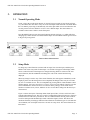
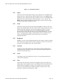
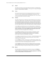
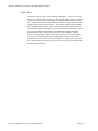
ESI VLS-2000 Video Line Scaler Operating ManualVersion 1.2
ESI
VLS-2000
Video Line Scaler
Operating Manual
Version 1.2
October 3, 2003
ESI VLS-2000 Video Line Scaler Operating Manual
Page 1
ESI VLS-2000 Video Line Scaler Operating ManualVersion 1.2
TABLE OF CONTENTS
1.
INTRODUCTION.....................................................................................................................................4
2.
INSTALLATION AND SETUP ................................................................................................................5
2.1 .Connections .......................................................................................................................................5
2.1.1 SVideo Input .............................................................................................................................5
2.1.2 Video Input................................................................................................................................5
2.1.3 YCrCb Input..............................................................................................................................5
2.1.4 HDTV Input ..............................................................................................................................5
2.1.5 RGB/YPrPb Output ...................................................................................................................6
2.1.6 Power Input ...............................................................................................................................6
2.2 .Output Setup ......................................................................................................................................6
2.2.1 Output: ......................................................................................................................................6
2.2.2 Scaling ......................................................................................................................................6
2.2.3 Screen........................................................................................................................................6
2.2.4 Sync ..........................................................................................................................................6
3.
OPERATION............................................................................................................................................8
3.1 .Normal Operating Mode.....................................................................................................................8
3.2 .Setup Mode ........................................................................................................................................8
3.2.1 Input........................................................................................................................................10
3.2.2 Load ........................................................................................................................................10
3.2.3 Brightness ...............................................................................................................................10
3.2.4 Contrast...................................................................................................................................10
3.2.5 Color .......................................................................................................................................10
3.2.6 Tint .........................................................................................................................................10
3.2.7 Detail.......................................................................................................................................11
3.2.8 Noise .......................................................................................................................................11
ESI VLS-2000 Video Line Scaler Operating Manual
Page 2
ESI VLS-2000 Video Line Scaler Operating ManualVersion 1.2
3.2.9 Motion .................................................................................................................................... 11
3.2.10 Black................................................................................................................................... 11
3.2.11 Source ................................................................................................................................. 12
3.2.12 Save .................................................................................................................................... 14
4.
TECHNICAL SPECIFICATIONS .......................................................................................................... 15
4.1. Video Inputs .................................................................................................................................... 15
4.2. Video Outputs.................................................................................................................................. 15
4.3. Controls........................................................................................................................................... 15
4.4. Input Stage ...................................................................................................................................... 15
4.5. Video Processing Stage.................................................................................................................... 16
4.6. Output Stage.................................................................................................................................... 16
4.7. Power .............................................................................................................................................. 16
ESI VLS-2000 Video Line Scaler Operating Manual
Page 3
ESI VLS-2000 Video Line Scaler Operating ManualVersion 1.2
1.
INTRODUCTION
The ESI VLS-2000 extends the capabilities of high definition projectors, monitors, and other highresolution display devices. It provides the ability to view a wide range of video sources at the full
capabilities of the display. The VLS-2000 contains sophisticated video processing electronics, which will
de-interlace, re-scale, sharpen, and reformat as necessary to provide the clearest, smoothest viewing
regardless of the video source.
The VLS-2000 has a sophisticated set of features, which together allow any display system to operate with
multiple video sources, originating from DVD, Film, Video, or Still Cameras. The VLS-2000
automatically selects the proper enhancements to perform, optimizing the video stream to provide the best
possible viewing experience within the capabilities of the display system. Some of the features provided
are:
• Video De-interlacing – Conversion of slow, 30 frames per second image (Interlaced), to a fast 60
frames per second image (Progressive). This eliminates flickering and doubles the amount of
detail the eyes see each frame.
• Film Reconstruction – Studio conversion of Film to Video requires movies to be re-timed from 24
frames per second to 30 frames per second. The VLS-2000 analyses the video and recognizes the
source as film, which allows it to perfectly reconstruct the original film frames.
• Line Doubling, Tripling, Quadrupling, and Scaling – Regardless of the format of the display
device, the VLS-2000 allows conversion of the video source to a format which is optimized for the
display device. A video source with less video lines than the display can be expanded, with new
lines added, calculated from surrounding lines with algorithms that minimize annoying artifacts.
• Image Sharpening – Special filters use information from surrounding lines and other frames to
reconstruct the original image, regardless of the limitations of TV transmission and recording. All
the information present in the signal is extracted, and used to help sharpen the displayed image.
• Format Conversion – Regardless of whether the original source was a video camera (4:3 format)
or motion picture (16:9 format) , the picture will be converted to appear correctly on the display
system. A TV movie will show up centered in the middle of a movie screen, while a Hollywood
movie will appear in the shape that the director intended it to be watched.
• Picture Adjustment – Besides the standard Brightness, Contrast, Color, and Tint, the VLS-2000
allows black level, noise filtering, and detail to be adjusted on an input-by-input basis. These are
automatically saved and restored when that input is selected. This allows switching from DVD to
cable TV to any other source, without having to adjust the projector.
ESI VLS-2000 Video Line Scaler Operating Manual
Page 4
ESI VLS-2000 Video Line Scaler Operating ManualVersion 1.2
2.
INSTALLATION AND SETUP
2.1
Connections
Figure 2 shows the rear panel layout of the VLS-2000. Input connections are grouped on the left
side of the panel. The Output connector is to the right of the Inputs, and the Power connection is
at the far right.
Figure 2 : VLS-2000 Rear Panel Layout
2.1.1
SVideo Input
Connect an S-Video source to this input, using a standard S-Video cable. If the source
equipment has both S-Video and Video connectors, S-Video is preferable to maintain
the highest possible video quality.
2.1.2
Video Input
Connect a composite video source to this input, using a video quality Phono style
cable. If the source equipment has both S-Video and Video connectors, S-Video is
preferable to maintain the highest possible video quality.
2.1.3
YCrCb Input
Connect a Component Video source to this input, using three video quality Phono
style cables. The video source should be labeled to match these three connectors. Do
not connect RGB video sources to this input. YCrCb provides the highest possible
video quality and should be used whenever the source equipment provides it.
2.1.4
HDTV Input
Connect a direct video source to this input. This signal is a pass-thru when selected,
allowing high definition sources to be switched to the projector input. No processing
is performed on this input, so the format, whether YprPb, or RGB, should match the
requirements of the Display System. This will allow the use of high definition sources
which need no video processing. It also allows multiple VLS-2000 units to be chained
together to expand the number of available sources.
ESI VLS-2000 Video Line Scaler Operating Manual
Page 5
ESI VLS-2000 Video Line Scaler Operating ManualVersion 1.2
2.1.5
RGB/YPrPb Output
Connect this to the Display System. This could be a Projector, High Definition TV, or
Monitor. The VLS-2000 may be configured to connect to RGB or YPrPb Display
Systems, with any sync requirement (HV, Sync-On-Y, Sync-On-Green, Tri-Level, or
Composite). For connection to equipment with Phono or BNC connectors, breakout
cables are available. Consult your dealer.
2.1.6
Power Input
The VLS-2000 is provided with a universal AC power supply. This will automatically
sense line voltage from 90 Volts AC to 264 Volts AC, at line frequency from 47 Hz to
63 Hz. This allows connections anywhere in the world. Plug the small power plug
from the power supply into the Power input jack, and connect the black line cord from
the power supply to the wall outlet.
2.2
Output Setup
It is important to set up the VLS-2000 output prior to turning on your display system. Some
projectors and monitors can be damaged if run for any length of time with the wrong scan rates
or improper sync signals. Section 3 of this manual shows how to set up operating parameters.
There are four output settings which need to be set up for your display device
2.2.1
Output:
This must be set up to match your display device. If it has input connections labeled
“R”, “G”, and “B”, or a 15 pin plug labeled “RGB”, set this setting to RGB. If your
connections are labeled “Y”, “Pr”, and “Pb”, set this to YPrPb.
2.2.2
Scaling
This must be set to match the resolution of your projector. Typically, it would be set to
the maximum resolution of your projector. 640x480, 800x600, and 1024x768 are
common settings for projectors and monitors designed for computer use. 480p, 720p,
and 960p are common resolutions for High definition TVs and projectors, and
1365x1k is a common size for new D-ILA projectors.
2.2.3
Screen
This should match the shape of your screen and/or projector, measured as a ratio of
width to height. Set it to 4:3 for computer or TV shaped screens, and to 16:9 for wide
screens intended for movie viewing. This setting allows the VLS-2000 to perform any
necessary scaling to make any size image fit your display.
2.2.4
Sync
The sync type must be determined by looking at your display device manual.
Generally, devices which connect with a 15 pin VGA style cable, or 5 separate cables
labeled R, G, B, H, and V will use the H-V Pos or H-V Neg setting. Three wire
connections to RGB monitors will need the RGsB setting. Three wire connections to
Component input monitors will need the YsPrPb setting. Some newer High
Definition monitors require Tr-Level sync require the TriLevel setting, and if you
ESI VLS-2000 Video Line Scaler Operating Manual
Page 6
ESI VLS-2000 Video Line Scaler Operating ManualVersion 1.2
have a 4 wire system, with only one composite sync wire, the Composit setting may
be required.
ESI VLS-2000 Video Line Scaler Operating Manual
Page 7
ESI VLS-2000 Video Line Scaler Operating ManualVersion 1.2
3.
OPERATION
3.1
Normal Operating Mode
Figure 3 shows the overall menu structure. In Normal Operating Mode (Top 4 blocks in Figure
3.1), the buttons allow the choice of any one of the four inputs connected to the VLS-2000. When
the VLS-2000 is powered up, it automatically selects the input which was selected when the unit
was last powered off. Press SELECT or UP to view a different input. The same buttons are
available on the remote control as on the front panel.
Press the MENU button to enter Setup Mode (Bottom 4 blocks in Figure 3.1), which will allow
changing any control function associated with that input. Press the MENU button again to return
to Regular Operating Mode.
Table 3.1 Basic Menu Stucture
3.2
Setup Mode
To change any control function associated with an input, first select the input, and then press
MENU. This enters Setup Mode for that input. A second line will appear on the display which
allows a control function of that input to be changed. Pressing SELECT will choose the next
control function, and UP and DOWN will change the value of the control function being
displayed.
When any change is made to any of the control functions, the result appears immediately on the
Display System. Once the changes have been completed, the changed values may be saved into
any one of 3 available Presets. This is accomplished by pressing SELECT until the Save control
function appears. Use UP to select Preset1, Preset2, or Preset3. Press SELECT again to save the
control information in the chosen Preset. To return to factory settings, use the Load control
function to load the Factory Preset, and then use Save to write these settings into the Preset you
want restored.
Figure 3-2 shows the layout of the Setup Menu. Each input (Video, S-Video, and YCrCb) has 3
available independent presets. This gives a total of 9 independent control function sets, which are
remembered even if the unit is powered off. The VLS-2000 remembers the last preset loaded or
saved for each input and automatically reloads it when that input is chosen. This allows the
maximum flexibility in setting up different control functions for different types of video material.
At a minimum, each used input needs to have at least one setup saved. The control functions are
listed below.
ESI VLS-2000 Video Line Scaler Operating Manual
Page 8
ESI VLS-2000 Video Line Scaler Operating ManualVersion 1.2
ESI VLS-2000 Video Line Scaler Operating Manual
Page 9
ESI VLS-2000 Video Line Scaler Operating ManualVersion 1.2
Figure 3.2 – Setup Menu Structure
3.2.1
Input
This chooses the VLS-2000 input to display on the display device. The Video setting
displays the device connected to the connector labeled “Video”. The S-Video setting
displays the device connected to the connector labeled “S-Video”. The YCrCb setting
displays the device connected to the connectors labeled “Y”, “Pr”, and “Pb”. The
HDTV setting connects the display device to the HDTV connector. No processing is
performed on this signal in the HDTV setting.
3.2.2
Load
This allows recall of previously stored settings for Brightness, Contrast, Color, Tint,
Detail, Noise, Motion, Black, and Source. There are three separate presets for each of
the three inputs (No settings are necessary for the HDTV pass-thru). To recall a
preset, use the UP and DOWN buttons to choose Preset1, Preset2, or Preset3.
Pressing SELECT again will cause the preset to be loaded from memory. “*Loading
Preset*” will appear on the display to acknowledge the action. To load the factory
values, select the Factory settings. On power up, Preset1 for each input is
automatically loaded.
3.2.3
Brightness
Brightness is used to set the background dark areas of the display. Set this to get black
areas of the screen to appear correctly. This will display on a scale of 0 to 100. If you
hold in the UP or DOWN buttons, this will ramp quickly.
3.2.4
Contrast
Contrast is set to get the brightest areas of the picture to appear with sharp detail,
without blooming or distortion of white areas, and without losing the distinction of
off-white areas near white areas.
3.2.5
Color
This setting sets the color saturation level. This is set to get the proper amount of
color into the video picture.
3.2.6
Tint
This sets the tint of the picture. It shifts colors slightly to get the best match to the
original image. This is typically set by feel by setting the value which yields the most
natural skin tones. Brightness, Contrast, Color, and Tint can be set up to better
accuracy by using commercially available test patterns on DVD, such as “Video
Essentials”, available at most DVD movie outlets.
ESI VLS-2000 Video Line Scaler Operating Manual
Page 10
ESI VLS-2000 Video Line Scaler Operating ManualVersion 1.2
3.2.7
Detail
This setting sets up the level of fine image-detail processing the VLS-2000 performs,
on a scale of 0 to 10. The nominal setting is 5, but edges can be sharpened with higher
numbers, or softened with lower numbers.
3.2.8
Noise
This setting controls the amount of noise filtering performed by the VLS-2000, on a
scale of 0 to 10. The 5 setting provides nominal filtering. For broadcast or cable
sources, more filtering may be preferable, while high quality sources, such as DVD or
Laser disc may be better viewed at lower settings.
3.2.9
Motion
This setting controls the type of motion processing performed by the VLS-2000. This
should be set to Auto except for some limited cases. The VLS-2000 has sophisticated
processing hardware which, in automatic mode, continuously analyzes the content of
the video signal and optimizes the processing to provide the best viewing experience.
The Auto mode switches between three different types of processing (Video, Film, and
Still). The additional settings on this control simply limit the switching of algorithms.
If set to Video, the information from successive interlaced frames is combined with
motion processing to compensate for the movement of objects in the picture during the
frames. This setting is used for video originating from video cameras, which capture
images at 60 frames per second, then transmitting the information ½frame at a time.
Most home and TV network originated video is of this type.
If set to Film, the information from successive frames is reconstructed to exactly
match the original movie film frames. This reconstruction is made possible by
advanced logic in the VLS-2000 which detects and reverses the “3:2 pulldown”
process used to convert movie film timing to video timing.
If set to Still, the information from successive frames is combined and sharpened with
no motion estimation. This gives the sharpest possible picture, but will result in
visible artifacts on moving objects.
If set to Vid/Flm, the automatic switching logic is prohibited from switching to Still
mode. This should only be used for known Film sources, and eliminates the occasional
switch into and out of static mode during still portions of the film.
If set to Vid/Stl, the transition to Film mode is prohibited. This may be used for the
output of digital cameras or home video cameras, but otherwise, needlessly prohibits
the best possible motion processing from activating if a Film source is detected.
3.2.10
Black
This setting enhances the black level for home theater viewing. Use the Enhance
setting to eliminate any remaining dark grey on the edges of black scenes. Normal is
used if this enhancement has already been performed at the input source (i.e. the DVD
source has already had Black Level Enhancement set)
ESI VLS-2000 Video Line Scaler Operating Manual
Page 11
ESI VLS-2000 Video Line Scaler Operating ManualVersion 1.2
3.2.11
Source
This tells the VLS-2000 what type of video source material is being presented to the
device input. Combined with the Screen setup, the VLS automatically calculates the
best image transformations to perform to get the largest possible image in the correct
aspect ration on the display. Source should be set to either 16:9, 4:3Full, or 4:3LtrBx,
depending on the format of the supplied input. Figure 3-3 shows the 6 possible
combinations of input Source and output Screen, with the image processing that will
be performed.
Some examples of setup combinations are given to show the flexibility provided by the
VLS-2000, when connected to a 4:3 format projector or monitor:
Showing a cable TV broadcast, set Source to 4:3Full to display the video on
the entire screen.
Showing an anamorphic DVD movie on a 4:3 monitor, set the DVD output to
16:9 and let the VLS-2000 do the scaling to letterbox format by setting source
to 16:9.
Showing an anamorphic DVD movie on a 4:3 computer type projector, set the
DVD output to 16:9 and let the VLS-2000 do the scaling to letterbox format by
setting source to 16:9. Display the image on a wide screen, with the black
areas above and below the boundaries of the screen.
Showing a cable TV movie which has been formatted and broadcast in
letterbox format, select 4:3LtrBx or 4:3Full to display as a letterbox image.
Some examples of setup combinations are given when connected to a 16:9 format
projector or monitor:
Showing an anamorphic DVD movie, set the DVD output to 16:9 and set
Source to 16:9.
Showing a cable TV video broadcast, set Source to 4:3Full to display the video
centered on the screen with black areas left and right.
Showing a cable TV movie which has been formatted and broadcast in
letterbox format, select 4:3LtrBx to re-scale the image to fill the entire 16:9
screen.
ESI VLS-2000 Video Line Scaler Operating Manual
Page 12
ESI VLS-2000 Video Line Scaler Operating ManualVersion 1.2
Output Screen
Input Source
16:9 Screen
4:3 Screen
No scaling performed. Image is
displayed without change.
16:9 image is Vertically scaled down
to fit in 4:3 format, centered vertically
on the screen, with black areas added
top and bottom.
4:3 image is Horizontally scaled down
to fit in 4:3 format, centered on the
screen, with black areas added right
and left.
No scaling performed. Image is
displayed without change.
16:9 portion of image is stretched
vertically to fill the entire screen.
No scaling performed. Image is
displayed without change
16:9
Film or Anamorphic Source
4:3 Full
TV, Computer or Video Source
4:3 Letterbox
Film Source Formatted for TV
Figure 3-3 – Input Source to Output Screen Translation
ESI VLS-2000 Video Line Scaler Operating Manual
Page 13
ESI VLS-2000 Video Line Scaler Operating ManualVersion 1.2
3.2.12
Save
This allows saving a group of control settings for Brightness, Contrast, Color, Tint,
Detail, Noise, Motion, Black, and Source. As an example, Input 1 might be connected
to cable TV. For movies, the settings might be slightly different than those used for
sports events. In that case the settings for movies would be stored in Preset1, and the
settings for sports events stored in Preset2. These could be simply recalled with the
Load function when that source is again viewed. There are three separate presets for
each of the three inputs (No settings are necessary for the HDTV pass-thru). To save a
preset, use the UP and DOWN buttons to choose Preset1, Preset2, or Preset3.
Pressing SELECT again will cause the preset to be saved to memory. “*Storing
Preset*” will appear on the display to acknowledge the action. To reset the factory
values, go to Load and select the factory settings, then Save these values into the
desired Preset. Control values saved will be retained even if power is lost to the unit.
Your most used settings should be saved to Preset1, since this is what is loaded when
the unit is first powered up.
ESI VLS-2000 Video Line Scaler Operating Manual
Page 14
ESI VLS-2000 Video Line Scaler Operating ManualVersion 1.2
4.
TECHNICAL SPECIFICATIONS
4.1
Video Inputs
Composite
1 V pp
S-Video
Y – 700 mv pp
C – 286 mv pp
Component (YCrCb)
Y – 1 V pp
Cr – 700 mv pp
Cb – 700 mv pp
HDTV
D15F (Progressive)
Note: All inputs are NTSC or PAL interlaced video except HDTV
4.2
Video Outputs
15 Pin female DB15 connector (VGA style).
Progressive scan, 59.94 hz frame rate (50 hz PAL).
Settable line rate for all major computer or TV standards
4.3
H-V Mode
RGB - 700 mv pp
Separate H and V TTL Sync, 4 V pp
Selectable Positive or Negative Sync Polarity
RGsB mode
RG - 700 mv pp
G – 1V pp, with embedded composite sync
YsPrPb mode
PrPb - 700 mv pp
Y – 1V pp, with embedded composite sync
Tri-Level mode
PrPb - 700 mv pp, with Tri-Level sync
Y – 1V pp, with Tri-Level sync
Composite mode
Composite sync on H and V, 4 V pp
Controls
Brightness, Contrast, Color, Tint
Detail Enhancement, Noise Filtering, Motion Processing, Black Level
Output Type (RGB or YprPb)
Output Scaling (640x480, 480p, 800x600, 720p, 1024x768, 960p, 1365x1024)
Output Screen Aspect Ratio (16:9, 4:3)
Output Sync Type (H-V, Sync on G, Sync on Y, Tri-level, Composite)
4.4
Input Stage
High quality adaptive Luma comb filtering
Multi line Chroma Comb filter.
ESI VLS-2000 Video Line Scaler Operating Manual
Page 15
ESI VLS-2000 Video Line Scaler Operating ManualVersion 1.2
Low noise YCrCb input stage.
4.5
Video Processing Stage
Automatic Film (3:2 pull-down) detection and reconstruction processing.
Automatic Video detection and adaptive motion processing.
Automatic Still Video / Computer graphics detection and enhancement.
Format conversion for all combinations of input and output aspect ratios.
Scaling and re-timing to all common display resolutions.
4.6
Output Stage
High quality 10-bit DAC.
Fully programmable Sync for any Display System.
4.7
Power
93-247 Volts, 47-63Hz (Universal External Switching Power Supply)
12 Volts DC, 1.5 Amperes at power input jack.
ESI VLS-2000 Video Line Scaler Operating Manual
Page 16