1
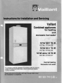
Instructionsfor Installation
and Servicing
Vaillant
Combined
appliances
for heating
and
domestichot water
VCW2Ol1T3 W
GC-No.47 04403
VCW2511T3 W
GC-No.47 04405
VCW-sine18 T3 W
GC-No.47 O4401
Centralheating
Domestichot water
This aoolianceshall be installedin accordancewith the relevant
Codes of Practiceby BritishGas or by an authorizedinstaller
C O R G Im e m b e r )
These instructions should be left near the gas meter when
the installation is completed.
1 lntrcduction
Contents
P4e1 . lntroduction
2 . Construction of aPPliance
J.
Generalreouirements
4 . lnstallation of boiler
Water circulation system
Commissioningand testing
7. Assembling
8 . Servicingof combi heater
q
Foultfinding
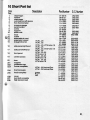
1 0 . Short list of ports
1 1 .Technicaldata
2
2
4
^l
;\
;;
,;
46
61
64
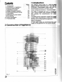
The Vaillant csnbi boiler is a wall-rnqrrH
natural draught open-flued (or in the case d
VCW-sine, room-sealed) boiler with buifr it
instantaneous domestic hot water heater,
"TechnicalDda-.
Outputratingsare shown in
The boiler is designed for use in a sealed c
open vented system with pumped circuldin
ahd includes the instantaneous hot w&
sYSIem.
Circulatingpump,expansionvessel (forseald
system only), terminal box, control and sdetf
devicesare providedwith the appliance.
Note to Installers
ln hard water areas we recommend the d
supply to the appliance is via a scale reducer.
of ApPliance
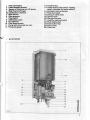
2 Construction
-24
9
11
23
22
14
18
19
21
o
N
3
trin
2
I
o
l Fkrcorinection
2 Down draught diverter
3 Sensorof overheat cut-off device
4 Mainheatexchanger
4a Combustion chamber
5 Main hrmer
6 Gasgovernor
7 Flowswitch
8 Differential valve
9 DC solenoid
10 Fbwthermometer
11 Pump with automaticair vent
12 Pressuregauge
\a-
l
1 3 Terminalbox
1 4 Switchboard (mainswitch, heating
switch, domestic hot water switch)
1 5 Domesticheat exchanger
1 7 Flowthermostat
' 1 8 Pressure relief valve
1 9 Service cock
20 Gas service cock
2 1 Overflow (optional extra)
22 Push button start
23 Push button stop
24 Pilot burner
25 Piezo unit
air vent points
o
o
'6
=
o
3 Generalrequirements
cP 342 Centralizedhot water suPPlY
3.1 Related documents
The installationof the combi boiler must be in
accordancewith the relevant requirementsof
the Gas Safety Begulations.),buildingregulations, l.E.E. Regulations,and the byelaws ot
the localWater Undertaking.
It should be in accordancealso with any relevant requirementsof the localauthorityand the
relevani recommendations of the following
British Standard Codes of Practice:
CP 331 Installationof pipes and meters for
lown gas,
Part 3: Low Pressure installation
pipes.
BS 5376 Selectionand installation
of gas space heating(1. and 2. family
gases).
Part 2 Boilers of rated inPut not
exceeding60 kW.
BS 5449 Central heating for domestic
oremrses.
Part 1 Forced circulationhot water
syslems.
otherthan
Part2 Buildings
dwellings.
BS 5440 Flues and air suPPlY for
3.2 Location
3.2.1 Vcwqjle (8.F. APP|iance)
The locationdhosenfor the combi boiler must
oermit the provisions of a satisfactory flue
ierminal. The location must also provide
adequatespacefor servicingand air circulation
around the heater. The combi boiler may be
installed in any room, although particular
attention is cjrawnto the requirementsof the
l.E.E. Regulations and, in Scotland, the
electricalprovisionsof the buildingregulations,
with respect to the installationof the combi
boilerin a room containinga bath or shower.
of the combiboilerwillbe
Wherethe installation
in an unusuallocation,specialproceduresmay
be necessary and BS 5546 and BS 5376 : 2
give detailedguidanceon this aspect.
A compartment used to enclose the combi
boiler must be designed and constructed
specificallyfor this purpose. An existing cupboard or iompartment may be used provided
that it is modifiedfor the purpose.
Details of essential features of cupboardi
compartmentdesign includingairingcupboard
instdllationsare given in BS 5376 : 2.
Part 1 Individualdwellings,
appliancesof rated input not
ding 60 kW (1. and 2. familY
Part1 Flues
Part2 Air suPPlY.
B S5 4 4 6 : 1 9 7 9
Installationof gas hot
suppliesfor domesticPurPoses
We liketo drawyourattentiontothefactthd
connection for the filling or replenishingol a
sealedprimarycircuitfrom a supplypipe is can
ditionalupon a water undertakingseekingaa
obtainingconsentfora relaxationotits Byeh
3 and 8 (1)from the Secretary of State.
.) Gas Safety Regulation,1972:
It is the law that all gas appliancesare ins{d
by competentpersons in accordancewith t:
above regulations.Failureto installappliara ,
correctlybould lead to prosecution.This b L
your own interest and that of safety to erisG
ihat the law is compliedwith.
3.2.2 VCW (O.F. APPliance)
The locationchosen for the combi boilernrrsl
permit the provisionof a satisfactoryflue ad
bdequate air supply. The location must fu
provide adequate space for servicingard *
circulationaroundthe appliance.
The combi boilermust not be installedin a rqq
containing a bath or shower. In addition,it b
recommendedthat the combi boilershouldrd
be fittedin a bedroom.Where the installationd
the combi boilerwill be in an unusualposilb\
special proceduresmay be necessaryand BS
5'326:2 and BS 5546give detailedguidanceot
this aspect.A compartmentusedto enclosete
combi boilermustbe designedand construec
specificallyfor this purpose. An existingopbbard or iompartment may be used provided
that it is modifiedfor the purpose.
Details of essential features of cupboard
compartmentdesign includingairingcupboad
installationsare given in BS 5376 : 2.
3.3Gassupply
the availabilityof an adequatesupplyof gas.
3.3.1Servicepipes
atthe An existingservicepipe must not be usedwit>
Thelocalgasregionshouldbeconsulted
planningstagein orderto establish out prior consultationwith the local gas regiorl
installation
4
3.3.2 Meters
3.3.3 lnstallation pipes
A gas meter is connectedto the servicepipe by Installationpipesshouldbe fittedin accordance
the local gas region or a local gas region with CP 331 :3.
contractor.
Pipework from the meter to the combi boiler
An existingmetershouldbe checkedto ensure must be of a adequatesize. Do not use pipesof
that it is capable of passing an additional a smaller size than the combi boiler gas
2.95 ms/h (106 CFH) before the VCW 20 connection.
(or 3.38 mslh(122 CFH) beforethe VCW 25 or
The complete installationmust be tested for
2.47 melh(89 CFH) beforethe VCW-sine18) is soundness
as describedin the above Code.
installed.
3.4 Flue system
Detailedrecommendationsfor fluing are given
in BS 5440 : 1. Thefollowingnotesare intended
to give generalguidance.
\=i= 3.4.1 VCW-sine (B.F. Appliance)
The boiler must be installed so that the flue
terminalis exposedto the externalair.
Terminationshould be on a clear expanse of
wall;
the terminal being preferably not less than
600 mm (2 ft.) awayfrom acorner, a recessora
projecilon.
Do not install the terminal:
a) Within 300 mm (1 ft.) measured vertically
from the bottomof an openablewindow,air
vent, or any other ventilationopening.
b) Within 300 mm (1 ft.) above adjacent
ground level.
c) Within 600 mm (2 ft.) of any surfacefacing
the terminal.
d) lmmediatelybeneatheaves or a balcony.
Where the lowest part of the termlnal is less
than 2 m (6,6 ft.) abovethe levelof any ground,
balcony, flat roof or place to which people have
access, the terminal must by protected by a
guardof durablematerial.A terminalprotective
guard is availableas an optionalextra with the
combi boiler.The air inleVproductsoutlet duct
and the terminalof the boilermust not be closer
than 50 mm (2 in.) to combustible material.
Detailed recommendationson Drotectionof
combustiblematerialare given in BS 5440 : 1.
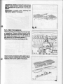
3.4.2 VCW (O.F. Appliance)
Detailedrecommendationsfor fluing are given
in BS 5440 : 1. The followingnotesare intended
to give generalguidance.
The cross sectional area of the flue fitted to the
combi boiler must be not less than the area of
the flue outlet of the appliance.An adapter is
suppliedto allowthe fittingof 125 mm steelflue
pipe or 125 mm lightasbestoscementflue pipe.
When fitting flue pipes a split socket
connector must be fitted to ensure easy
disconnection of the flue pipe (see page 13
f i g .1 6 ) .
Flue pipes and fittings should be constructed
from one of the followingmaterials:
a) Asbestoscement,
b) Aluminiumor stainlesssteel,
c) Cast-iron acid-resistant vitreous enamel
lined.
lf double-walledflue pipe is used it shouldbe of
a type acceptable to British Gas.
lf a chimneyis used it preferablyshouldbe one
that is composedof or lined with a nonporous
acid-resistant material. (Chimneys lined
with salt-glazed earthenware pipes are
acceptableif the pipes comply with BS 65 and
540 : 1.) A flue pipe constructedfrom one of the
materialsin a) to c) aboveshouldform the initial
connection to lined chimneys. Where a
chimneyis to be usedwhich is not composedof
or lined with a non-porous acid-resistant
materialit shouldbe linedwith a stainlesssteel
flexibleflue liner or any other liner that is of a
type acceptableto BritishGas. The internaldiameter of the liner must not be less than shown
in the technicaldata and the number of joints
mustbe kepttoaminimum.lf thefluelinerisnot
to be connected directly to the combi boiler
draught diveder a flue pipe which is
constructedfrom one of the materialsin a) to c)
above shouldform the connectionbetweenthe
draughtdiverterand flue liner.
Before connecting the combi boiler to, or
inserting a liner into, a flue that has been
previouslyused, the flue must be thoroughly
swept clean of any soot and loose material.lf a
register plate, restrictorplate, damper etc. is
fitted in the flue, it must be removed before
connectingthe combi boiler to, or insertinga
liner into,the flue.
The flue should terminate in accordancewith
the relevant recommendationsgiven in BS
5440:1, table4.
A terminal of a type that has been tested and
found satisfactory by British Gas should be
fittedat the flue outlet.
The point of termination must not be within
600 mm (2 ft.) of an openablewindow,air vent
or any other ventilationopening.
c
3.5 Air supPlY
Detailed recommendationsfor air supply are
given in BS 5440 : 2. The followingnotes are
intendedto give generalguidance.
minimum effective area of permanent air
vent(s) is specifiedbelow and is relatedto the
maximumrated heat inputof the unit.
cmz
108
130
Appliance
vcw20/1
vcw25/1
in.2
16
20
3.5.1 Room or internal space air supply
The room or space in which the boiler is
located must have a permanentair vent' This
vent must be eitherdirectto the outsideair or to
must
an adiacent
'have room or internalspace which
a permanent air vent of at least
itself
i-n" same sizd direct to the outside air. The
The balancedfluedcombiboiler,VCW-sine,
doesnot requirethe roomor internalspaceto
airvent.
havea oermanent
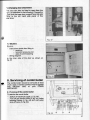
3.5.2 Cupboard or compartment air supply
Where the combi boiler is to be installedin a
cuoboardor compartment,permanentair vents
are required (for cooling purposes and in the
case 6f open flued appliances also for
combustionand flue dilution)in the cupboardor
compaftment at high and low level' These air
vents must either communicatewith the room
or internalspace or be directto outsideair.
The minimumetfectiveareas of the permanent
air vents required in the cupboard or
compartmentare specifiedbelow (Tab. 1) and
are ielated to the niaximum rated heat inputof
the unit.
Air vent areas
Pos.of
air vents
High
Level
LOW
Level
VCW-sine
280
320
235
{42)
(50)
(36,5)
Airdirectfrom
outside
(inr)
cm2
I
(21)
140
(25)
160
(18,5)
120
vcw20/1
vcw25i1
VCW-sine
560
640
,235
(84)
(100)
(36,5)
280
320
120
Airfromroomor
space
internal
(inr)
cmz
,
vcw20/1
vcw25/1
(42)
(50)
(18,5)
Tab.1
Note: Both air vents must communicatewith
the same room or internalspace or must
be both on the same wall to the outside
air.
Where cupboard or compartment air vents
communichtewith the room or internalspace
the room or internalspace must itself have a
permanentair vent(s)as specifiedin 3.5.1.
3.5.3 Effect of an extract fan
lf there is anv tvpe of extract fan fitted in the
oremisesthere i6 the possibilitythat if adequate
iir inlet area from outside is not provided
ipittag" of the products from the open flued
combi boilersflue could occur when the extract
fan is in operation.Where such installations
occur a spiilagetest as detailedin BS 5440.: 1
must be carriedout and any necessaryactlon
taken.
3.6 Water circulation system
Detailed recommendations for the water
circulationsystem are given in BS 5376 :2' BS
5449 :1 (Jorsmall bore and micro bore central
heatinq svstems) and CP 342- the following
notes ire of particularimportance.Pipework
not forming pbrt ot the useful heating surface
should belnsulated to help prevent heat loss
and possiblefreezing,particularlywhere pipes
are run through roof spaces and ventilated
underfloorsPaces.
Draininq taps must be located in accessible
which permitthe drainingof the whole
oosition-s
svstem includingthe combi heaterand the hot
water system. Dlainingtaps should be at least
1/2 in. nominalsize and be in accordancewith
BS 2879.
6
F
,
\-
3.7 Electrical supply
Wiring external to the combi boiler must
be installed in accordance with the l.E.E.
Regulationsand any local regulationswhich
apply.
The combi boiler is supplied for 22O/24OV,
50 Hz.Fuseratingis 3 A.
Thecombiboilerhasto be connected
directto
the mainselectricity
supplyusingthe internal
terminalbox.
Forwiringinstructions
seeparagraph
4.7.
4 lnstallationof boiler
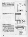
(16 in.) must be available at the front of the
appliance to enable the combi boiler to be
servrceo.
Serviceclearanceof 150 mm (6 inches)either
side is reouired.
For the open flue type appliancesVCW 2011
and 25/1 an additional clearance is requiredfor
the flue. The combi boiler is supplied in
2 cartons,one containingthe boiler,the other
the installation accessories. An additional
cartoncontainingthe terminal/ductassemblyis
deliveredwith the balancedflued appliance.
4.1 General
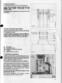
The combi boiler is to be wall-mountedand a
verticalflat area of wall is requiredwhich must
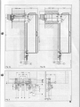
measureas shown on templateThis area does not include clearance for
installationand servicing. lf the appliance is
fitted on a wall of combustible material, the wall
should be protected by a sheet of fireproof
material.
In addition.a minimum clearance of 400 mm
o
o
c
o 6
>oFO.
(U
A
B
vcw20/1
vcw25/1
1095mm
1 1 6 1m m
130mm
125mmwithadaoter
22mm
15mm
D
'l00mm
107mm
Er
K
weight
Fig.3
Alldimensions
in mm
1014mm
1080mm
Electricalmains
connection
59 kg
60 kg
distancerequiredto
) Minimum
removeexpansion
vessel.
Installation
mayrequire
anotherdistance.
7
!
;
Fig.4
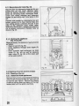
4.2 Fluing
Forthe installationof the flue set (wallcase)ot a
combi boiler, we reter-to rne
-in.t"llation
room sealed
instructions No' 806901
.!-o"t"i"
iniluded with everyflue set.
4.3 Connection
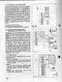
A oeneral view of pipeworkfor gas and water
coinection is given in fig. 5.
The following procedure describes the
installation.
The wall distance(to the finishedwall) of pipewoit<toi gas and hbatingsystem is.50mm and
40 mm for domesticwater PiPework'
8
in mm
Alldimensions
t
1. Compression union (flow of heating
svstem)
z. S-ervicecock (flow of heating system)
3. Domestichot water connection
4. Union (gas)
5. Gas service cock
6. Cold water connectionwith shut-offvalve
7. Servicecock (returnof heatingsystem)
8. Over flow (optionalextra)
9. Pressure relief valve
10. Compression union (return of heating
system)
11. Connectionsupport
23. Frameof appliance(lowerconnection)'
,,4
I
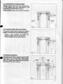
4.3.1 lnstallation aids
4.3.1.1Open flued combi boiler
After fixingthe connectinggroup to thewall put
the template in positionancl mark posltlonsoI
fixing holes.
The type of fixing used will depend on the type
of wall.
II
**!**o
4.3.1.2Roomsealedcombi boiler
assembly,
After installinqthe terminal/duct
onthefixingbolts(1) anddrill
hanothetempi-ate
the5 holeswith8 mm(5/16inches)diameterto
fit the connectinggroup.Use the alternative
fixingholeswherenecessary.
rl
fl
I
|
+ 1 -
I
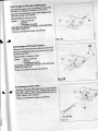
4.3.2Domesticcold and hot watel
connection
- Flush out all loreign matter from the
supply pipe before connecting to the
connectinggrouP.
- Fit the domesticmainswater pipe to the
union(2) and the
riqhthandcompression
h5twaterpipeto the lefthandcompression
union(3).
ln hardwaterareathemainssupplyto union
(2)shouldbe viaa scalereducer'
- bhect domesticwatersystemfor soundness.
amaximumworking
boilerhas
N.B.Thecombi
oressureof 10 bar. lf water pressure
bxceedsthis a pressurereducingvalve
willhaveto befittedto coldwaterinlet.
10
ll
)l
II
{33 Gonnection of heating system
Fledirtgsyslemflow and returnshouldbe in
2. rrtn copper pipe and connectedto the
cqrtecting groupas shownin fig. 9.
Ftl lhe heatingsystemandtestfor soundness.
I
I
I
t
4.3.4Pressurerelief valve and overflow
The pressurereliefvalve,requiredfor a sealed
system,is includedintothe connectinggroup.
- Screw in the overflow (4) below the
pressurereliefvalveintothedrainline.
(Tobe availableas
an optionalextra.)
I
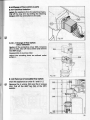
4.4Fittingthe appliance
Closeservicecocks(5),unscrewunionnuts(6)
and take off the olive-shapedplastic plugS.
Refit union nuts (6) with brass'compr6ssi-on
rings (7). Close mainswaterservicecock (8)
andunscrewthe unionnutF(9).
*-A-6
4.4.1 Open flued aPPliance
Unpack boiler from carton and remove side
oarieislas in 8.1'1.),lint arrestor(as in 8'2'2)
inO pait ing aids as well as plasticcaps.from
the ionneciions. Insert the appliancewltn tne
connection tubes downwards into the comoiession unionsof the servicecocks and hang
it on to the bolts(1)and fasten screws (10)'
unions(6)andunionnuts
Fastencompression
washers(11)'
attached
thb
using
ig),
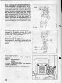
4.4.2 Balanced f lued aPPliance
Unoack boiler from carton and remove side
Janels(as in 8.1.1.) and packingaidsas wellas
blastic baps from the connections.Fit the flue
buct (20) irtitntne 2 sheet metal screws (22) to
the t;le6copic duct (16) of the terminal/duct
assemblY.
Insertthe appliancewith the connectiontubes
downward iirio the compressionunions of the
service cocks and hang it on to the threaded
bolts of the wall case (1), fig. 14. Fasten nuts,
compressionunions(6, fig. 13) and unionnuts
is, iig. 13) using the attached washers
(11,fig.13).
20 21
F i g .1 4
12
1 Fixingbolts
16 Telescopicduct
19, 22 Sheet metal screw
20 Flue duct
2'l Flue bend
45 Gcconnection
Frtthe gasservicecock(5) to the appliance.
Cleil out all foreign matter from the gas
s.Dpty pipe before connecting to the
service cock!
Connectthegassupplypipeto theservicecock
andtighten.
F--i
a
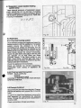
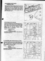
4.6 Flueconnection (openflued)
Insertflue intothe draughtdiverterafterfitting
the adapterprovided.
A split socket connector must be fitted to
ensure easy disconnection of the flue to
simplifyremovalof themainheatexchanger.
21. Fluepipe
22. Draughtdiverter
22.aCollarotthedraughtdiverter
24. Adapter
25. Splitsocketconnector
a
4.7Electricalconnections
Vaillantcombiboilersarecompletelywired.
lt is
onlynecessary
to connecttheelectrical
mains
andtheroomthermostat.Connectto220/240v
50 Hz.electrical
sgpplyfused3 A.
Warning!Thisappliancemust be earthed.
Afterremoving
theterminalboxcoverconnect
the mainsto theterminal(c)of theappliance
in
the manner indicatedbelow. A cardboard
labelshowingthe correctmainsconnection
to
the terminalsis in the terminalbox. Please
removebeforeconnecting.
Do not connectthe electricalsupply to the
pump terminals(b).
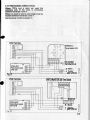
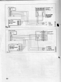
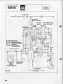
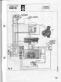
Full wiring diagrams for various control
schemesareshownintig.21Io 24.
t
t
t
l
l
l
r
i
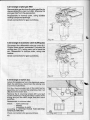
4.7.1 Connection of the mains cable
As shown on the figures the live conductor
*nicn is colouredbrown must be connectedto
the terminalmarked with a L on the appliance
inO to tne tetminalmarkedL or colouredred on
the Dluq.The neutral wire colouredblue must
6e ioni"ct"O to the terminal markedwith a N
on tne aoptianceand to the terminalmarked N
oi coioureOblack on the plug' The earthwire
colouredqreen and yellow must be connected
i" rn" otine two teiminals marked O on the
"opiiin"" and to the terminalmarkedwrthan E
oi svmbol O or coloured green or green ano
vellow on the plug. lf no room thermostat or
iimer is installbd,-terminal3 and 4 must be
linked.
a. Fuses 2 A (delayaction).
b. Terminalsfor pump regulating'
i- Terminalsfor hpplianceinput connections'
1
@@_a
..'\L*=
-j
LEf,-l
@a
Fig.18
Connection of Vaillant room
4.7.2
-thermostat with clock (no' 394)
Connectionof room thermostatis made to the
terminiri g anO4. lt is recommendedto installa
Vaillantroom thermostat(RT)with accelerating
resistance. The room thermostat must De
inJiiiteo on an inner wall which is influenced
neiiner Ov current of air nor by the sun, in the
livinq rooin. Duringthe installationof the room
therftostatthe manufacturer'sindicationsmust
be followed. For the sake of economy and
iotfurt the Vaillant combi boiler should
be requlated by a room thermostat with
icceleiating resiitance. lf the room thermostat
is not connected,to operate the heating system
ior i"iting purposes'afterthe installation,the
,nit "an bi op6ratedby provisionalapplication
oi a OriOgebetween ihe terminals 3 and 4'
Wfren tfrE room thermostat is wired in this
bridgemust be removed.
4.7.3 PumP control
The pump may be controlledin one of three
ways (see fig. 20):
SettinqI (as suPPlied)
For-use with clock and room thermostat
systems. Pump is switched off by clock or
room thermostat.
Settingll
For"use with thermostatic radiator valve
svstems. Pump is switched off by clock or
o'asvalve switih when gas valve closes'
selttingttl
Purip runs Permanently and
affected bY external controls.
is
t
Sz
not
i
14
1,7, Thcrmostatic radiator valves
l$rere TRVs and a clock are used the
ilibfrirg side of the clock is connected
betreen teminals 3 and 4.
lYhereno clockis useda wire bridgemustbe
insertedbetweenlerminals3 and 4.
Setthe pumpcontrolto positionll.
VCW-Terminal
RANDALL
TimeSwitch 103
Do not link
terminal3 & 6
VAILLANT
Roomthermostat
VBT378
0
Fig.21
VCW-Terminal
N Mains
L Supply
24OV/5OHz
I
SWITCHMASTER
300TimeSwitch
a
REMOVE
O
VAILLANT
Roomthermostat
VRT378
0
1) Link N and 2
2) Link L and:4
N Mains
L Supply
24OVlsOHz
3
15
HORSTMANN 125
COFONET
Time Switch
Do not link
terminals
Land5!
VAILLANT
Foomlhetmostat
vRT 3 78
N
t.in"
L
SuPPIY
J
2r0v/50H2
3
o
l':-
Fig.23
O
VAILLANT
Roomthermostat
VRT 378
0
16
N Mains
L SUPPIY
+ 24ovl5oHz
B
E
-9-
6 = O
E;E
9 p 5
"9=i
;
E$s
a
a
E
l
I
I
Ib
o
.o
(,
CD
lo
lt^
a
cl
c
o l
988x: o* o' t
3
(o
I
o(g
F
i
i
p
o
c
o
o
a?
o
o
3
o
'
o
=
",1;
E Y
r()
AI
.st,
tt
E
o
o
o
c
'=
15
14
13
21
'12
n
23
24
25
77
26
11
10
9
I
7
6
5
70
71
73
54
5:l
30
2A
n
31
58
/-ffi
61
7A
46
1
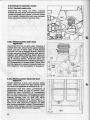
0t[|il[[|ll
32
Fig.26
1 service cock
3 flow switch
4 thermostaticelement
5 gas inlet
6 automaticvalve
7 pilot adiustmentscrew
I switch box/FFD
9 oush button start
10 pilotvalve
11 push buttonstop
12 thermo-magnet
13 micro switch
14 thermo-couple
15 pilotburner
18
16 sensorof overheatcut-offdevice
17 main heat excnanger
18 air ventingscrew
19 expansionvesset
20 main burner
21 gas governor ..
22 mainburneradjustmentscrew
i3 double-stagemain burnervalve
24 venturi
25 differentialvalve
26 DC solenoid
i8 expansionvessel pressurecontrol
29 pump
-'_-43
N--.a.-:.*.
water
o"'"""'ic
3?:li"#3[?t!l3ll
circutr
heating
i
i
32
39 mainswitch
41 terminal
tlo"o"*
X3 rn"rto""'
hotwater
58 micro-switch
59 watersedlon .
60 coldwaterinlel
61 watergovernor.
63 hotwateroutlel
switch
3e!3il'J3-:Y':ilvarcr
control
70 electronic
71 NTCresistor
*"*"'
"1.1H,$3#3f;'ftL
1?
systembypass
78
$i[#s$:rrtt:"'
t.
53 micro-switcn
ll
micro'switcn
54
79 relaY
19
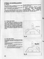
5 Watercirculatingsystem
5.1 General
The combi boiler is suitable for use on most
miniboreand microboresystems.
It is recommendedto use copper tubing to BS
2871 :1for water carryingPiPework.
The use of horizontal pipe runs should be
avoided whereverpossiblein order to prevent
air collectingin the system. lf horizontalruns
are unavoidablethe pipes should rise upwards
towards a vent point.
For qeneral quidance reference should
be mide to ihe British Gas publication
INSTALLATION
MATERIAL AND
DOMESTIC
SPECIFICATIONS FOR
-,
CENTRALHEATINGAND HOTWATER B
:1.
BS
5449
and
BS
5376:2
to
and
5.1.1SinglePiPesYstem
The heat emittersare installedon a closed
circuit.The necessarywaterquantityfor every
mustbe ensured.This
heatemitter(radiator)
can be done for instanceby using suction
of theradiators.
fittinosinthereturnconnection
on the
sizesshallbe calculated
The-radiator
aroundthe
distribution
basis of temperature
circuit.
Fig.28
5.1.2Two-pipe system
The radiatorsare installedparalleland the flow
temperature therefore is the same for every
radiator.
Typicalcentralheatinginstallationare shown in
the followingfigures.
NOTE: 5.2 to 5.5 are applicableto both open
and sealed systems.
N.B. The primaryfillingpoint may be placedat
any convenientpoint on the circuit.
FillingPoint
Fig.29
20
S2Gontols
Vdilt
cofiti bcilers are ready for connecting
oleebcLft:d
mains.
W$Gn conhds (24OV) may be connected as
sfwn h figures 21 to 24.
53 lrolating valves
The +dianoe shall be installed with isolatinq
(service cocks) as described unde-r
dws
4-3_3.
5.'tGirculating pump
The cirolating pump is included into the combi
boiler. The remaining conveying capacity can
betaken from the diagram.
SssYstem by-pass
A system by-pass is included into the combi
bdler.
800
176
1000
220
1200
264
14c,0
308
1600 L/h
352 cPH
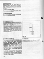
5.6 Openvented system
lf it is requiredto usethe combiheaterin ooen
systemsit is possibleto do so without'anv
modification to the combi heater. W6
recommendto fit the expansionpipe(2) at the
isofationvalve(no.7,tig. 12)wherenormallv
the pressurereliefvalveis fitted.The relevani
BritishStandardsandCodesof Practiceas well
a: otl.gr requirementsinvolved(see also 3.1)
shouldbe strictlyobserved.
Minstatichead:0.15bar(5'water)
Maxstatichead:2.0bar(67'water)
see BS5449clause24.1
2 expansionpipe
3 expansioncistern
7 overflowpipe
Fig.31
21
5.7Sealedsystems
Sealed systems do not requireleed and
openventsetc'only gooo
cisterns,
exDansion
ouitiWraOiatorvalve'sand fittingsshouldbe
detrlmenlal
Jsedin orderto preventexcessive
topping-uP.
5.7.1Pressureleliefvalve
This is requiredon all sealedsystemsand is
shownin 4'3.4'
connected'as
5.7.2Pressuregauge
Thisis factoryfittedto theboilerandshowsthe
circuit.
in thePrimary
pressure
3
5.7.3Expansionvessel
into
vesselis incorporated
A 15 litresexpansion
ihe combib6ilersuitablefor a sealedheatingiuit". with a maximumwater contents of
260litres(57.2lmP.galls')
lf thenominalcapacityof thebuilt-inexpansion
vesselis not sufficientfor the heatingsys,tem.
of old
in case of modernization
itor-instance
iioen Jvstems)an additionalexpansionve-ssel
of the
to the sideconnection
cin Oeinstatt6d
ieturn service cock in connectionwith the
pressurereliefvalve.
Fig.32
5.7.5 Pipework
5.7.4Fillingand makeuP
All oioeworkshall be securelysupported,shall
a
via
The svstemshouldbe filledwith water
where possible'
lillingpointfittedat a convenientpoint run'n'eatlyand be concealed
seoar6te
on' the neati-nbcircuit.Where local Water
Authority Regulationallows, a temporary
connectionto-the mainsmay b,eused' The
connectionmust be removeclwhen lllllng ls
completed. Where local Water Authority
Reqirlation does not allow temporary
a sealedsystemfillerpumpwith
corinection,
breaktankmustbe used.The heatingsystem
witt not be filled automaticallyfrom the
domesticside.
ln principle,sealedsystemsdo not require
faciliti6s,but experiencehas
waier mat<e-up
shownthatsomemake-upmaybe necessary'
Methodsof fillingsealedsystemsaregivenin
A of BS 5376:2.
appendix
22
6 Cornmissioning
and
testing
6, 1 El€ctrical installation
r-e,'rinary electricalsysiem checks
to ensure
+€sflcal safety shall be carried out by a
:r,mpetent person. Those checks are outliired
r tne INSTRUCTIONSFOR BR|T|SH GAS
IiIULTIMETER.
t
t
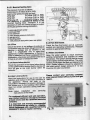
6.2 Gas installation
Tne whole of the gas installation,includinqthe
reter. should be inspected and testej for
soundnessand purged in accordancewith the
iecommendationsof Cp 331 : 3.
6.3 Water circulation system
The whole oJthe systemshould be flushedout
wtrn Dotncotd and hot water. Ensureall valves
are open.
With the combi boilerfitted,the system should
be fiiled and air locks cteared.V6nt tnJOoifei
throughthe 4 vent pointsshown ln tiq. iand'2.
Loosenthe black cap on the automaiicair vent
oy 1-z turns. Vent all heat emittersand check
for.water soundness.On a sealed svstem
fiti
untilthe pressuregauge registerst.s iraiizr.S
PSI).
(The system should be filled with water
either
from a sealed system filler pump with a break
or
by
a
method of filling given in BS
La_lK.
5376 : 2, appendixA.)
Checkoperationof safetyvalve.Releasewater
Tromrne systemuntilthe initialsystempressure
oL.-t,zoat ts atatned, taking into account anv
otnerence.in height between the pressur6
gauge and rhe point at which the higtiest
heat
emtnerts connected_
Fig.33
6.4 Lighting the combi boiter
The first lightingof the applianceshall be done
oy a quatttiedfitteronly.He shallalso give clear
verbat instructions to the user on how to
operatethe combi boiler,controlsand systemi
generally.Light the combi boiler as described
separatelyin the "lnstructionsfor use,,.
6.4,1 Gas soundness
Test for gas soundness around boiler qas
components using sense of smell and l6ak
detectionfluid.
6.4.2 Main burner pressure
Pull off the plug of the NTC-resistorand test
the
matn Durner pressure at the main burnei
pressuretest point.
23
6.4.2.1NominalheatinginPut
mustbe as follows:
Thepressure
mbar(8.08in' WG)
intetbressure:20
mainburnerpressure(coldandhot):
9.0mbar(3.61in.WG)
vcw 2011
9.0mbar(3.61in.WG)
vcw 2511
10.6mbar(4.26in.wG)
18
VCW-sine
The apolianceis regulatedat factoryto the
.b'ti"5i neating influt. Thereforeit is not
n"lJ""urv to a[6r thbsettingof.inputor output
duringinstallation'
"itne g"d gouernor
1
2
3
+
5
6
7
screw
pilotadiustment
pilotgasfilter
DCsolenoid
testPoint
mainburnerPressure
gasgovenor
blockingPlate
inLipti.irte testpoint(nearrearplate)
6.4.3Flue
Checkthatthereis no spillageof products,of
fromthedowndraughtdiverterby
JomOustion
carryinqa spillagetest as detalleoIn t:D
il6' i r. thppiicaoteonly to open{lued
ol llamesIn
Checkappearance
aooliances.)
lii,irl"-"iihrtish thatihereis adequateair for
LturitLn, checkalsoasoutlinedunder3'5'3
ii'tn"l"li lriv tvpeof extractfan fitted'
B
6.4.5Flow thermostat
Checkthe flow thermostatand all automatic
Jontiofsare operatingsatisfactorily'Readjust
settings.
controlsto appropriate
6.5Watersoundness
Allow the water system to reach maximum
woif<inqtemperatuieand examinefor water
iornon""...ihe systemshouldthenbe turned
offind rapidlydrainedwhilestillhot'Thewater
iu.t". shouldagainbe filledandclearedof air
6.4.4Flametailuredevice
idcis. Sealedsistems shouldbe adjustedto
devic.e
failure
flame
the
of
operation
Checkthe
initialsystemdesignpressureof 1,2bar'
will
the
device
the
that
ensure
to
"'"'ini donoiuoiler
forwatersoundness.
Examine
60
within
burner
main
the
"iir,li "tt sit to
seconos.
Please contact your senticing company'
6.6User'sinstructions
nearestVaillint office oryour local gas
for use to the userfor Vo-u-r
Handthe instructions
region,
l"T"niio"unOinstructin the safeoperation.of
ii. aooriince. Advise the user of the
oi"cauiibns necessaryto preventdamageto
ihe svstemand to the buildingif th-esystem
JoLJ'not remainoperativeduringfrost conditions.
Note: Leave installation and servicing
at the meter'
instructions
For continued efficient and safe operation,
"iirt-viiiii"ni ippliance should be serviced
liLaiion"e a'vearbv a qualifiedservicing
company'
It is important and strongly re-comm.ended
that ariangementsare made for a -!44!!!!9
ilt cA-sr6ereLtwith a qualified servicing F i g . 3 5
to ensure regular servicing'
ififfiv
24
o
o
N
=
o
o
7 Assembling
0
ieotace the plug to the NTC (Negative
:ernperature
Coefficient) resistor before
:ssembling.
=
()
a
7.1Lint arrestor(openflued appliance)
Tofitthelintarrestor
hangit intothefrontsideof
thelowerretaining
frameandclipit againstthe
appilance.
7.2 Side panels
Push the 2 side panels from the front onto the
boilerand screwto the upperand lowerframes
with two pairs of captive slotted screws. lf the
door isre^quired to open from the right see
section7.6.
o
+=
o
Fig.38
25
7.3 Screen Plate
Positionthe left hand edge of the screen plate
unOertne side panel.Pressthe slideunderthe
eJoe ot tne riqhthandsidepaneland alignwith
the-slotsin the screenplate.Securethe screen
otit" *itn 3 screws as indicated in fig 39'
ileolace the thermostatknob'
7.4 Front Panel
Press the front panel including the grey
enameledcentre sbction onto the boiler' the 4
bolts engage in the spring-boltedsupports'
7.5 Door
The door supports are attached at the right
hand side panelof the appliance(dooropening
from the left).The door is fittedas follows:place
the door into the upper supportand fix to lower
supportwith the hinge screw.
26
I
6 Changing door attachment
-r€
roor can also be fitted to open from the
-i:--. as describedin the following:Changethe
-rc,er.and the lowerdoor supportfrom the right
-,ar'. to the left hand side panel of the
:E€} an@.
7.7 Stickers
Stickon
- instructionssheet after filling in
- serialno.,
- test point pressureand
- date of commissioning
- wiringdiagram
to the inner side of the door as shown on
fio.43.
8. Servicingof combi boiler
$
-
The combiboilershouldbe servicedat least
oncea year.A servicecontractmaybe agreecl
with BRITISH GAS or Your CORGI
INSTALLER.
8.1Turningoff the combi boiler
To servicethecombiboiler
- Switchoff electricalsupply(1, tig.44).
- Turnoff gas servicecock(3,fig.44),boiler
isolatingvalves(4, tig. 44) and cold water
shut-offvalve(5, tig. 44).
@ e a-]r*Lrz
I \,{\
@__ ta,
8.1.1Removingoutercase(fig.44)
hingepin(b)and
Removedoorby unscrewing
oullinqdoor out and down. Removeupper
banei Oy pullingoutwards.Removegauge
jlanel bir iemovingboiler thermostatknob'
'screw
over rockei switchesand loosening
screws(c) and slidingrighthandpanelto the
left.
top and
Removeside panelsby unscrewing
buttomscrews(d) to clearinternalclipsand
then pullingpanelsoutwardsand off' In the
case of the balancedflued combi boiler
VCW-sineremovethe 4 screwsand washers
(A) to removecombustionchambercase as
showninfig.45.
{eir
'ry
t
8.1.2 Drainingthe aPPliance
(fig.44 and 46)
When necessary,the appliancemay be drained
as follows.
- Open air vent (18,fig. 46) .
- Drain appliance through draln nlpple (tr,
fig. 46).
- D-raindomestic heat exchanger via drain
screw (C, fig. 46) as well as pressure
relief vdlve (D, fig. 46) at the lower part
of the water section.
8.2 Cleaning of burner and lint arrestor
8.2.1 Cleaning of burner
8.2.1.1Balanced llued appliances
Removethe burnerby unscrewingthe retaining
unionnut (E),the pilotairfilter(F),takecare not
to lose the pilot inlector. Remove the thermo
couple by pullingdown and taking off the high
ten6ionlead from the ignitionelectrode.
28
L
l,lrcrer the retainingscrews (T) and remove
Cileanbumers, injectorsnozzlesand
trcs.
certbly with a light brushor a vacuum
il
CEE'.
Fbsenble in reverseorder, replacingthe
m-r bumergasketif necessary.
Fig.48
82.1.2 Open llued appliance
Remove bumers by levering off burner bar with
a screwdriver. Remove thermo-couple probe
by pulling downwards from pilot assembly so
that probe disengaged from circlip. Remove
pilot assembly.by unscrewing screw (F).
Remove burner bar by unscrewing nut (E).
Cleanburnersandinjectorswitha lightbrushor
vacuumcleaner.Reassemble
in reverseorder,
replacingmainburnergasketif necessary.
29
8.2.2Cleaningof lint arrestor
(openfluedaPPliances)
Removethe lintarrestorby pullingdownward
of the
the partwhichis nearthe connections
appliance.
Cleanwiththelightbrushor a vacuumcleaner.
in reverseorder.
Reassemble
8.3 Cleaning of main heat exchanger
8.3.1 Balanced flued aPPliances
Removeburneras under8.2.1.1. Slackenthe 2
screws holdingthe flue hood and slide hood up
as far as possible.
Remove sensor (3) of overheat cut-off
device from pocket on left hand side of heat
exchanger. Undo union nuts (G) on heat
exchangerunionsand slackenlockingnuts (H)
above them. Removeheat exchanger.
Clean heating body especially fins carefully
with hot waier, detergents and brush. lf
necessary descale with propriety descaling
aqent. Do not bend the fins. lf necessary,
carefullywith screwdriver.
st-raighten
8.3.2 Open flued aPPliance
Remove burner assembly as under 82.1 .2.
Slackensplit collar.
Slacken the 2 screws holding the draught
diverterand slide draughtdiverterup as far as
possible. Remove sensor (3) of the overheat
but-offdevicefrom the pocketon left hand side
of the heat exchanger.Undo union nuts (G) on
the heat exchangerunionsand slackinglocking
nuts (H) abovethem. Removeheat exchanger'
clean heatingbody and especiallyfins carefully
with hot water, detergent and brush. lf
necessary,descale with proprietarydescaling
aoent. Do not bend the fins, if necessary
carefully with screwdriver.
st"raighten
30
L
-:_Tovethe venturi
-a-c connection tubesituatedin the riqht_
of the heatingO"Ov.b'nZci
:,:.e ando-ring,cleanboreand-repla6"
- -gcessary.
;_*;;
=;lp9emble
..in reverse oroer, ensurino
A:shers
fittedin heat "".n",ig"i'r;;;X
.are
: J rlueductengagedin spigotin flr;
6rrn*;;;i
8.4Descalingof domesticheatexchanger
111:l]r_etcessarytodescatethedomestic-heat
excnanger
removethe tl
.1"_.-:y'q
"ndt-n"',i:",ru
saus"
i:Ji:?"T;
-nscrewing
the2 tubingnuts.For6et-tei;;;";i
:o the connections.
reriove the b;;;;e;;fi;;
tne S retatning;;;ily
=i:"^ p^y.unscrewing
the 3 u.nion
nuts(K) "io-ir,"'"2
-o_
.1?I--qy9
rarn
lng_
screws(l). Descaleb,jr".ti" rlt"?
descating
agents
:11e_:
anOrinl-e
?yptoryetary
arerwardswith clean water.
3ea:semble in reverse oroer
using new
/yashers.
:
8.5 Cleaning of water section
I?_-l"Toy.q. the water section unscrew the
'nrernat..
(N) and the external- (M)";"i;;
connectionsand loosenthe screw (L).
":tess to theconnections
unscrew
i:^,,!:tl
:ne towerretaining
frame.
Open the water section. Clean the water filter
(O) or replace,if necessary'Check diaphragm
tpj anO water governor (61), replace, if
necessary.
Reassemble in reverse order using new
washers.
Where stuffing gland needs replacingfit new
too to water section,incorporatingnew stuffing
box.
of differentialvalve
8.6Maintenance
Mark and disconnectthe two unions and
screws(Q).
unscrewthethreeretaining
Ooen differential valve and clean. Check
dihohraom and replace, if necessary. Check
eaiv ruininq pin of diaphragmdisc in stuffing
box. In casebi replacementof the stuffingbox'
it is recommendableto replacealso diaphragm
disc. Lubricatepin with suitablegrease.
Mark and disconnectthe two controllines and
clean by blowingthrough.
Reassemblein reverseorder.
Jt-
Fig.58
32
.
E-7Eryansion vessel (sealedheating
system onlY)
lnec* internalpressureof expansionvessel
*nir*r shouldbe 0,7 to 0,9 bar' if heating
is withoutpressure(black
srstemof appliance
gaugeat 0). Refillwith
:'al of build-inpressure
ar pump,if necessary.
i { : . - -t i f 5 f
I
l_
(
i
I
8.8Finaltests
I
o
tf
8.8.1Finaltest heatingsystem
o
the
open
nipples
and
Closealldrainscrewsand
3
lf
O
servicecocksto refillthe appliance. a sealed
svstem ensure the pressure is 1.2 bar
to 6.3. Switchon electricity,turn on
a-ccording
qas andstartthe appliance
as outlinedon the
;tickerattheinnersideofthef rontdoor.Check
flame failuredevicefor correctfunctioning.
Checkthe pilotflameand adjustwiththe pilot
rate adluster (7) so that there are three
seoarateflames.lf the flame profileis one
larqe,looseflame,increasegas rate until 3
seiarateflamesdevelop,as shownin fig.60a'
Replacepilotjet if necessary.
for soundness.
Checktheappliance
Check all controlsfor correct functioning'
reassembleouter casing of applianceas
under7.
s
8.8.2Finaltest electricalsystem
Check - earthcontinuity
polarity
resistanceto earth
according to INSTRUCTIONSFOR BBITISH
GAS MULTIMETER.
8.9 Change of Pilot iet
Disconnectthe pilottube from the pilot'Change
pilotjet and washer and reassemblein reverse
ordbr.
In case of an open-fluedapplianceremovethe
pilot assembly by unscrewing the retaining
bcrew. Changb the pilot jet and reassemblein
reverse order.
Check connectionsfor gas soundness.
8.10 Change of thermocouple
Disconnectthe retaining nut (R) and pull the
thermocoupleout of the thermocouplesupport.
Insert the new thermocouple fully into the
support. (ln case of VCW-sine seal the
thermolead into the bottom of the chamber
plate by a specialrubberwasher).Connectthe
retainingnut.
8.'l1 Change of sPark electrode
(VCW-sineonly)
Pull off the high voltage lead, remove the
retainingscrew(S), removethe sparkelectrode
and replace with the new electrode.
Reassemblein reverseorder,ensuringthat the
sparkgap from the electrodeto the flameshield
is 3 m;, takingcare not to overtightenthe f ixing
screw.
,,n[;5-o j
8.12 Change of NTC (negative temperature
coefficient) Plobe
Disconnect the AMP plug and unscrew the
NTC probe. Reassemblein reverseorder'
8.13 Change of automatic air vent
Drainthe applianceas under8'1 and 8.1.2.
Unscrew the automatic air vent by hand.
Reassemble in reverse order, screwing the
automaticair vent in bY hand onlY.
Open the lockingcap (LC) of the automaticair
vent by 1 -2 turns.
34
\,
|llf Change of flow switch or parts
t-1f.1 Electrical isolation
botde the appliance from the el6ctrical mains.
Pr.fl off the plug (S1) by shifting the retaining
(S2) top and bottom to the side.
Egu6
8.14.1.1Ghangeof flow switch
mirco switches
Sorinqoff the protectivecover (SG).Unscrew
(S4 or (S8),takeotf microswitchand remove
the AMPplugs.
in reverseorder.
Reassemble
Adjust the actuatinglever as outlinedunder
8.14.2.' 1.
8.14.2Removalol completeflow switch
as under8.1and8.1.2.
Draintheappliance
Removethe 4 unions(S3) and the 2 screws
(S4). Pult off the AMP tag (S5) of the NTC
resistor.
8.14.2.1Change of flow switch stuffing box
Remove complete flow switch as in 8.14.2.
Unscrew retainingscrew (S9) and take off the
micro switch assembly. Unscrew adiustment
nut (S10), remove lever assembly, remove 3
screws securing top cover, unscrew stuffing
box, remove both rubber seals and fit new
seals, ensuring washer is fitted between the
seals. Reassemblein reverseorder and adiust
lever assembly of the cold flow switch as
follows: Turn down the adjustmentnut (S10)
slowlyuntilmicroswitchclosesthe redto brown
circuitand make one more completeturn down.
8.14.2.2Change of thermostatic element
Unscrew the 3 retainingscrews (S11) and
remove the housing (S12). Reassemblein
reverseorder, using new washers.
8.14.2.3Changing internalseals
Removehousingas in 8.14.2.2.
Bemoveseals R1 and R2 and replacewith new
ones. Do not use any jointingcompoundor
grease.
8.14.3Reassembling
Reassemble in reverse order, using new
wasners.
Check - earth continuity
- PolaritY
- resistanceto earth
accordingto INSTRUCTIONSFOR BRITISH
GAS MULTIMETER.
Note: positionof notcheson plug as shown.
.to
\"
Af 5 Change ot piezo igniter
(VCW-sine only)
Elisconneclthe high voltage lead (pl) from the
i.d bolt. Removethe retaining screw (p2) and
remove the unit by springing the bracket.
Reassemble in reverse onier, ensuring that
krcding dimple in the bracket aligns wiih the
dd in the piezo unit.
fr=
b4
8.16 Change of DC solenoid
lsolate the appliance from the electrical mains.
llolg.coloy.r code and puil off the AMp ptugs
(Dl) from the micro switch as weil as the'Alrip
dugs (D2) from the DC solenoid socket.
Loosen the 2 retaining screws (Dg).
Beassemble in reverse ordel.
Check - earth continuity
- polarity
- resistance to earth
a€cordingto INSTRUCTIONSFOR BR|T|SH
GAS MULTIMETER.
8.17Changeof DCsolenoidmicro switch
lsolatethe appliancefromthe electricalmains.
NotethecolourcodeandpullofftheAMpoluoi
(Ml). Unscrewthe 2 retaining
- screwsiMi;.
Reassemble
in reverseorder.
Check - earthcontinuity
- polarity
- resistanceto earth
qcggrdingto TNSTRUCTTONS
FoR BRtTtsH
GASMULTIMETER.
l
l
ri
i
8.18Ghangeot pump
8.18.1Changeof completepump
as under8.'l and8.1.2.
Draintheappliance
mains.
fromtheelectrical
lsolatetheappliance
Openthe terminalbox of the pump.Notethe
colourcode of wiringand disconnectpump
cable.
connection
Unscrewthe automaticair vent(Pl ) by hand.
the 2 controllinesof the
Markand disconnect
thetubingnuts
valveby unscrewing
automatic
(P2). Loosenthe 2 pump unions(P3) and
unscrewthe bracketfixingscrew(P4)andthe
to
unionnut (P5)at the righthandconnection
the mainheatexchanger.
8.18.1.1Open flued boiler
Take otf connection to main heat exchanger
together with the pump as shown on fig. 75.
Reassemble in reverse order, using new
washer at the righthandconnectionto the maln
heat exchanger.
Screw in the automaticair vent by hand only.
Check - earth continuity
- polarity
- resistance to earth
according to INSTRUCTIONSFOR BRITISH
GAS MULTIMETER.
8.18.1.2Balanced flued boiler
Unscrewthe upperpump union (P3)and spring
off the pump as shownin fig. 76. Reassemblein
reverse order, using new washer at the right
hand connectionto the main heat exchanger.
Screw in the automaticair vent by hand only.
Check - earth continuity
- PolaritY
- resistance to earth
according to INSTRUCTIONSFOR BRITISH
GAS MULTIMETER.
38
5.
8-18.2Changeof pump head
onty
Draintheappliance
as under8.1andg.1.2.
lsolatetheappliance
fromthe
mains.
t-lpenthe terminalbox of the electrical
prmp. fVoieit-e
ggroyrcodeof the wirinsano'oisc[nn6ci
.jr,L.',i
iii!
p:llp,_ connecrioncabie. un.,jr"*
(p6)anop.urr
otrp-ump.ijE"o]
L"l:ll,lSscrews
lHrJvJisy*siEb
$":F:Ti_{{t,yiHl3lfl
n^eassemble
in reverseorder.Ta-ke;;;not
to
oamagethepackingring.
Check - earlhcontinuitv
- polarity
_
.. resistanceto earth
FoRBRrflsH
3iT'fl0flr,'#PTRUcT|oNS
0
8.19Changeof gas section
","
$H:3}lFift?:dif"tj3,.iil?i,i!:ffi
discorin
ecti
nstn6..i
ilioii'i,fi 3i):fi:.{li"JJJ
bytoosenins
tnee ieiainiis;;"";
i6fi"'o
8.19.1 Batanced flued appliance
pirot
assembrv
i""Jl:;"J:TiH"","#J:"{t?il
8.19-2
Openfluedappliance
pitotsuppon.by
unscrewinq
*ruy: the
screw(G3)'andihe ,;i;.'fi;;; the
l"_r3ll'.19
ihe a reiainiii'#;;:
lAli'9y;^l"move
(\rz+r,reptace valve seating,
springi ;t". ;;
inrev"'i"oio"i
,lsin'd
fiffi3,l",3"assemble
Checkconnections
forgassounctness.
\|
8.20Changeof gas governor
8.20.1Balancedfluedappliance
gas sectionas in
l-l:lgy"
unscrew the 4 retaininc 8.19 and 8.19.1.
i;;"";###1,3ffi_($3ln
3.'-T
?r."
*3
checkc6nne"ii"""'iJi,'i!t
I";l???rTr
8.20.2 Open flued appfiance
the, main burner as uncter
,T:fy:
8.2.1.2.
-
y_1s_9r9*,
screws ?d;;:
. tle retaining
'orOer,
.iJ#
in reverse
.l?^1.j9r91"
using
wasners,
if necessarv.
Check
connections
forgassoundness.
ffilr
8.21 Change of pilot gas filter
Removepilotgas linefrom the pilotgas filter by
disconnectingthe union nut (G6). Unscrewthe
pilotgas filterfrom the gas section.
Reassemble in reverse order, using suitable
sealingcompoundsparingly.
Check connectionsfor gas soundness.
8.22 Change of automatic valve stuffing box
Disconnectthe differentialvalve as under 8.6.
Control lines remain connected.Unscrew the
stuffing box (G7), taking care not to bend the
oin. Reasemble in reverse order. usino new
wasner.
Check connectionsfor gas soundness.
8.23 Change of switch box
lsolatethe appliancefrom the electricalmains.
Markthe pilotlines,disconnectthe tubingnuts
and remove oilot lines.
Pull the thermocoupleout of the pilot burner
assemblyand unscrewthe retainingunionnut
(82) from the switch box.
Remove the 2 retainingscrews (Bl) and pull
out the switchbox. Notethe colourcodes of the
wiring and pull the AMP plugs from the micro
switches.
Reassemblein reverseorder.
Check - earth continuity
- polarity
- resistanceto earth
accordingto INSTRUCTIONSFOR BRITISH
GAS MULTIMETER.
Checkconnections
for gas soundness.
40
v
""0
3?
3
i:Hl""ls
:g:ti
ffi:t'ru1"1
'm#,lx;l*:w',?::#3
a
bY
rePrace
and
valve stuffing box
8.24 Change of FFD
in reverseorder'
Reassemble
continuity
earth
Check
- PSlflillset:f,S,l,
,o" BR,''H
a"ft'$it'''-+?JU"JF'"*nn""'ionsforgassoundness'
6nJ"n
L
Fig.83
{,
buttons
8.25Changeof FFDPush
under8'23'
asoutlined
""t""" "" t*itch box
push
pulloutthe
and
(ffi)
io"r.ingr.ing
llm;
buttonto the tront'
in reverseorder'
Reassemble
Check -- earth.continuity
polarlry
B3
"A
b'ln-s+4"t3;'gKs
FoRBRrrrsH
""".rdi[
6nsvuirtuEren' gassoundness'
6n""n "onn""tionsfor
Fig.84
valve
8'26 Changeol Pilot
(85)
(84)andp9l!gut spring
ofuq
tn.
Unscrew
-€f
b t ;:flJfl:iin[i'f,lst;'igslas':n?"1"J'::
F
6io"t' utinga newwasher'
gassoundness'
Checxconiectionsfor
l. Ynllli
rtb
8.27 Change of thermo-magnet
Removethe switch box as outlinedunder8.23.
Removemicro-switchassemblyby unscrewing
the 2 retaining screws (88). Skaighten tap
washer (B9),unscrewretainingnut (B10),pull
out thermo-magnet (B11) carefully. Reassemblein reverseorder.
Check - earth continuity
Polarity
- resistance to earth
accordingto INSTRUCTIONSFOR BRITISH
GAS MULTIMETER.
Check connectionsfor gas soundness.
<G>
.-
3
rig.e6
<88
8.28 To open the control box
lsolatethe appliancefrom the electricalmains.
Open the main terminal box by removingthe
retainingscrew (C1).Remove the four
retainingscrews (C2).
Lift up the switch box and pull out slowly the
control box cover complete with the switch
board, printed circuit and terminal board. Pull
off the multiple plugs from the printed circuit.
Reassemblethe box in reverse order. When
replacing the screws, position the 2 star
washersdiagonallyto the screws.
8.29 Change of main swilch board
Take off the switch board as outlined under
8.28. Disconnect the mains cable from the
terminals.Unscrewthe 2 retainingscrews (C3)
and removethe p.c.b.withthe mainswitchfrom
the crontrolbox cover.
Reassemblein reverseorder.
Check - earth continuity
- polarity
- resistanceto earth
accordingto INSTRUCTIONSFOR BRITISH
GAS MULTIMETER,
b
,z-4.t -
"v4r(
Fig.BB
42
8.30Changeof micro-switchesof water
section
Opencontrolboxas in 8.28andremoveswitch
screw
box as in 8.23.Removethe adjustment
(C5) and take off the microswitchassembly.
PulloffAMPplugs(C4).
in reverseorder.
Reassemble
Check - earthcontinuity
- PolaritY
- resistancelo earth
FOR BRITISH
accordingto INSTRUCTIONS
GASMULTIMETER.
o
8.31Changeof overheatcut-off device
Openthecontrolboxas in 8.28andremovethe
switchboxas in 8.23.
Pull off the 2 plugs(CG)and the earthlead,
removethe saddleclip (C7),pull the sensor
(3, fig. 52) out of the main heat exchanger.
Unsciewthe 2 retainingscrews(C8),release
grommetfromboxand removecut-offdevice.
in reverseorder.
Reassemble
Check - earthcontinuity
- Polarity
- resistanceto earth
FOR BRITISH
accordingto INSTRUCTIONS
GASMULTIMETER.
forgassoundness.
Checkconnections
)
L
rt
8.32Changeof electronic P'c.b'
Openthe controlbox as outlinedunder8.28.
Uirscrewthe retainingscrew (C9) on the left
handsideof the controlbox.P.c.b.is heldon
key-holeslot, pull p.c.b. forward and to the
andwhitelead.
right.Pulloff multiplug
Reassemblein reverseorder and ensurethe
p.c.b.is locatedon the lefthandsideof plastic
peg.
Check - earthcontinuity
- polarity
- resistanceto earth
FOR BRITISH
accordingto INSTRUCTIONS
GASMULTIMETER.
8.33Ghangeof expansionvessel
8.33.1Domesticwater side
Disconnectthe tubing nut (W1), unscrew
bracketsecuringscrewandremoveexpansion
vesselcompletewith bracket.Unscrewvessel
from bracket.Reassemblewith new domestic
waterexpansionvesselin reverseorder.
8.33.2Heatingsystem open flued
appliances
Disconnect
the flue at splitcollar.Remove2
screwsand nuts,securingthe upperretaining
frame.Lift rear of frame clear of side frames
and rest it on top of draughtdiverter.Remove
screwssecuringdraughtdiverterand remove
togetherwith upperretainingframe.Remove
draughtdiverterretainingframe by removing
the 2 retainingscrews.Undothe union nut
(W3),movetheexpansionvesselupandtakeit
off. Reassemblein reverseorder,takingcare
thatthe expansionvesselis correctlyfixedinto
the2 supports.
Usenewwasher,if necessary.
8.33.3Heatingsystem balancedflued
appliance
lsolateelectricalmains and removemains
cable.Closeoff water and gas servicecocks
anddraintheappliance
as outlinedin 8.1.2.
Disconnectflow and return connectionsat
compressionjoints on top of service cock.
Disconnectgas connectionat compression
joint on top of gas cock.Disconnectdomestic
hot and coldconnections
on diaphragm
body.
Slacken locking nuts on flow and return
connections.Removenuts from bolts (1 in
fig. 14) on terminal/duct
assemblyRerirove
boilerfrom wall. Disconnect
sleevenut (W3)
and removeexpansionvessel.Reassemblein
reverseorder,takingcare that the expansion
vesselis correctlyfixedto the 2 supports.
:
44
\_)
8.34 Change ol thermometer
Pull the temperature sensor (U3) out of the
sensor tube. Press the 2 tongues into the
thermometerand pull it out to the front side'
Reassemblein reverseorder.
)
t
8.35 Change of manometer
Disconnectthe tubing nut (U1) ot the control
line and removethe fixing nut (U2).
Reassemblein reverseorder.
ffi\
v
A
w
b
t
^
8.36Changeol systembYPass
Close off flow and returnservicecocks and
in 8.1.2'
drainboileras outlined
nuts (V) and remove
2
union
the
Unscrew
valve.Unscrewthe3 screwsholdingthetopol
the valve. Renew diaphragmor spring as
Do not movespringadjustingnut'
necessary.
Reassemblein reverse order, using new
wasners.
S
9 Fault Finding
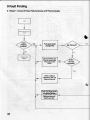
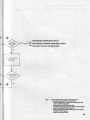
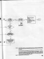
9.1 Sheet 1: Check of Flame Failure Device and Thermocouple
b
rsgas
pressure
available?
Push green button
and light Pilot.
Can Pilot be lit?
De-aeratePilot Gas
Pipe by unscrewing
Pilot Adlustmdnt
Screw.
ls Pilot
Gas Pipe
de-aerated?
Checkor clean,if
necessary,
PilotGas
FilterandPilotJet.
CheckPilotflamecorrect
size.CheckThermo'
Tip isclean. Check
Dositionedin flame.
Recitify any fault.
46
button
Releas€:green
afterabout
10seconds.
-
DaesPitot
Flame re-main
\
z Adiustment
ot PilotFlameand
Themocouple
Gheck Thermocouple
Vohage (min. 15 mV DC).
(Open circuit).
Voltage
satisfactory?
i
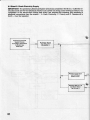
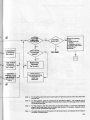
9.2 Sheet 2: Check Electricity Supply
IMPORTANT:The preliminaryElectricalSystemChecksas containedin the B.G.C.multimeterinstructionbook are the first electricalchecks lo be canied out during a fault findingprocedure.On
completion of the service/faultfinding task which has requiredthe breaking and remakirtgof
electricalconnectionsthen the checks - A. Earth Continuity,C. Polarityand D. Resistanceto
Earth - must be repeated.
PreliminaryElectlical
System Checks
accordingto Instructions
for BritishGas
Multimeter.
Push Main Switch
into posilion l.
Replacefaulty Neon
and refil Main
Switch Cover.
Replacefarlty P.C.B.
with Main Switch.
ReI. to note 1.
48
Cheek Operalingol HeatingSystem (Sheet3)
Check Operationot DomesticHot Water System (Sheel 6)
Check switch lor DomesticHot Water (She6t5)
Note
1 : Detach the Jollowing parts oithe control box:
- unscrew the cover of the terminal box
- unscrew upper part ot control box (2 screws) and
press it a little bit upwards
- unscret/v knob of boiler thermostat
- unscrew front panel ot control box with switch group
- pull off multicontactplugs Aand B
- remove printed circuit by loosening the two screws
beside the switch group
- install new orinted circuit
49
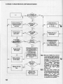
9.3. Sheet 3: Check Operation of Heating System
(Do not use domestichot Water, switchfor domestichot water remainsin PositionZl)
Can Pilot be Iit?
Switch give
. light? /
Push HeatingSwitch
into positionl.
' ls voltage \
240 V AC trom
ls Overheal
CufOfi
Device
of OverheatCut-Off-Device
@on P.CB
tat'f
50
Overheat
€*t
:,t-Otf Device.
eef. lo note 2.
ls voltage
2ZIOVAC
trom teminal
Does Main
Burner light?
Are external
Thermostats
tested?
Go to sheet 4
-:Eck contacts
d Overheat
:loff Device.
a€i. to note 3.
Fleplacefaulty
Thermostat.
Ret.to note5.
Check that
Multiplugs@ arid
: ile clean, tight
ild mrrectly
:r:siti.cned. Ref.
note 4.
Check external
Thermostalsaccorclino
'
to lnstructionstor
BritishGas
Multimeter.
Flepeatthe tollowing
checks:
A. Earth Continuity.
C. Polarily.
D. Besistanceto Earth
accordingto Instructions
for BritishGas
Multimeter.
Note 2: For re.s€tting, press the black rubber butlon on right hand side of control box behind the
terminal box.
Note 3: For this purpose, open the control box as describ€d in Note 1. The overheat cut-off
device isiitt(i on right hand side ofthe control box- Checkitthe flat plugs ofthe overheat
cut-otl device are tight.
Nole 4: For this purpose, open the control box as described in Note 1 Pull off the multicontact
plugs A and B and check that not contact lugs are bent. It necessary, readiust contact
iugS and reset multicontact plugs again.
Note 5: To check, disconnecf contrclsystemlrom terminals 3 and 4, and replace with wire loopto
run boiler in heating mode.
51
9.4 Sheet 4: Check Electronic and Hydraulic System
lsvoltage \
/
5tol5VDCatDC
Check that MultiplugA
connectionsare clean,
tight and correctly
positioned.
ls MultiplugA
tested?
Pull otf connection
of NTC probe.
Ref. to note 7.
ls NTC probe
tested?
Replacefaulty P.C.B.
with Main Switch.
Ref. to note 1.
ls Micro
Switchon
FFD tested?
Check grey connections
on FFD Micro Switch
lor 24OV AC from
Terminal5 to
connections.Replace
Micro Switch if faulty.
z ls voltage'
tol5VDCat
Solenoid?Ref. to
Replacefaulty
NTC probe.
Check black connections
on FFD Micro Switch
clean, tight and correctly
oositionedtor 5 to
15 V DC from brown
connectionon DC
solenoidto black FFD
connections.Reolace
Micro Switch if faulty Ret.
to note 8.
Re{itconnection
to NTC probe.
Hasfuseon
Electronic
P.C.B.
Replace0.25 Amp.
fuse.
Replacetaulty
ElectronicP.C.B.
Ref. to note 9.
52
Check that wire is
connectedto Terminal
l, ll or lll.
ReL to note 10
Nole 6: The D.C.-voltage of 5-15 V is
controlled at the supply terminals
of the solenoid vatue. Attention!
When the indicator tums.to the
left, the measuring lines must be
reversed.
On ignition ot the bumer there
must be a D"C.-voltage ot 15 V.
The
voltaqe
decroases
flow
io
the
according
temperature until the electronic
(at approx. 5. V D.C.-voltage)
tums oft the solenoid valve
(dead)
the
burner
and
extinguishes.
Note 7: Thls test shows whether the
NTc-sensor has an inner shorl
circuit (resistance down at zero).
For this purpose, pull the NTCsensor plug off when the
(Jlow
appliance
is
cool
temperature less lhan 50'C).
lf the electronic is satisfactory,
the appliance must operate.
Does
Pumprun?
DoesMaan
Burnerlight?
Are Pump
Setting
Terminals
tested?
Difterentral
Valve
tested?
240 V AC
lrom termrnal
5tol.
connectlons
on FFD
tested?
Checkpumpaccordrng
to lnstructionstor
BritishGas Multimeters,
Procedure9.
)
.!
Repeatthe following
cnecKS:
A. EarthContinuity.
C. Polarity.
D. Resistanceto Earth
accordingto Instructtons
for BritishGas
Multimeter.
ReplacefaultY
DC Solenoid.
Move Heating Switch
ON-OFF-ON.Diaphragm
pin on Difterential
Valve has to move
OUT-lN-OUT.If not,
'1.
Clean Venturi
2. CheckDiaphragm
at differentialvalve
and replace,jf necessary.
Ref. to note 11.
Attention! Pull otf the NTC-plug for a short time only because the normal temperalure control is
out of functionin that position.In this case the
applianceis only protectedby the overheatcutoff device.
Note 8: For this purpose, open the control box as described in
Note 1. Unscrew the pilot gas tubes of the thermoelectric casing and check it the black cables oJ the
micro switch are tight.
AfteMards installpilotgas tubes again
Before re-assemblingthe control box. check the finewire tuse of the eleitronic. lf necessary. replace it'
Attach plugs A and B again and re-assemble control
box.
9:
- For this purpose, open control box as described in
f.fote f . Pull'off the multicontactplugs A and B The
electronic-printed circuit can be removed .by
unscrewind the cross-recessed head screw on the left
hand siddof the control box. Pull out the printed
iircuit towards the front and pull off the multicontact
plug as well as the white cable.
Note 1O: Attention: External llnes must not be connected to the
terminalsl, ll and lll (shortcircuit!)
The black cable can be connected to terminal l, ll or I ll '
It must be checked whether the black cable is
connected tightlY enough
Note11: lf the movement of the diaphragm pin cannot be
checked optically. the pressure ditferential switch must
be removbd by unscrewing the 3 screws Do not
unscrew the two connection tubes!
Under perfect function the diaphragm pin cannot be
pushed back by hand, when pump oprates. lf lhis is,
however, possible, the venturi tube' Pressure
difierential iwitch, connectionstubes or pump, must be
checked. Special attention must be given to the tact
that the venturi O-ring ist nol damaged.
Install the electronic-printed circuit in reverse order'
RE
t"9.5 Sheet5: GheckSwitch for DomesticHot Water
(HeatingSwitchin position"O" do not usedomestichotWater)
Can Pilot be lit?
-Does Pilot
lamp in Main
Switchgive
1 light? -
SetSwitchfor
Domestic
HotWater
to positionI
Go to sheet 2
Device(Ret. to note 2)
and check connections
n if no voltaqe240 V
from lermin;l 5 to 4.
Check Micro Switch M1
by drawing hot water.
Micro Switch M1 has to
be actuated(closed)bv
Switch Lever.Observ6
piston rising!Adjustor
Micro SwitchM 1
no voltage240 V AC
from terminal4 to 5
Bel. to note 12
54
i
-
ls voltage
240VAClrom
Does Main
Bumer light?
Repeatthe tollowing
i
checks:
A. Earth Continuity
C. Polarity.
D. Resistanceto Earth
accordingto lnstructions
lor BritishGas
Multimeter.
NO
Go to sheet 4
ls Overheat
Cut-O'tf
Device
Switch M1 on
llow switch tested?
check that MultiplugA
connstions ile clean,
tight and corectly
oositioned.
"summei'is onlycontrolledby.themicroswitchM1ol theflowswitch'
Note | 2: Thetunction
iug mustoperatethe microswitch
Duringdomestichot t"t"iiiii'JtioiiinJi6itlct
Ml (close).
is necessary'
adiustment
lfthe microswitchis notoperatedby the contactlug' an
- switchotf
oDeration
(apglign-ce^9.t1!ot
tap
water
warm
For this Durpose,openthe
sivitch)bv meansof a
mainswitch).]lghten tnJiiri oi tne'iwititr'roit(topol flow
frg:::Jlli:"":H
LgftT#';lT'lJ$s'#"HlFr'IH!."*
)li,j"i notiouin tn" casingof the microswitch'
Note 13: See tigure 99 for micro switch Ml'
55
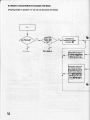
9.6 Sheet 6: Check Operation of Domestic Hot Water System
(Heatingswitch in position0 switchfor domestichot water in positionZll
Can Pilotbe lit?
lamp in Main
Switchgive
1 light?-z
Go to sheet 1
Go to sheel 2
Heating \
Switchto l. Does
. Main Burner
Set Heatinq
Switchlo "o-"
and draw hot water
Go to sheet 3
Note 14: For this purpose, open the control box as described in Note .l and remove front panel.
Thus the micro swilch is accessible and the movement of the switch Dinof the water section can be observed. Ooen
the warm water tap. With a water flow.quantity ol approx. 1 l/min. the switch pin must move and operate the micro
switch via the switch lever which can be adiusted. lf the switch pin of the wdter section does not hove, the water
section must be removed and checked (diaphragm).
lf the micro switch does not operate despite the fact that the switch pin moves, the switch lever must be readiusted.
For this, unscrewthe support ofthe micro switch and push itdownward until the switch lever contacts thetop oiwater
section. Fix the suOport in this Dosition.
56
-
lsvoltage \
240 V AC from
Does
Main Burnet
NO
R€peatthe tollowing
checlG:
A. EarthContinurty.
C. Polarity.
D. Resistanceto Earth
accordingto Instructions
tor BritishGas
Mullimeter.
4
lsWater
Slection
tested?
Swkh off electricRy,
t€move Control Box
Cover. Ooen and close
hot water iap. Diaphragm
Din of waler seclion has
to move up and down.
Draw otf one l/min. and
Pin has to be in upper
positjon. lf not, clean
Water Sedion according
seruicing instructions.
Ref. to note 14. Switch
on eleeticity.
-
'
lsvoltage
240 V AC trom
ls Micro
Swildt
acluated?
Close Control Box.
Adiust Swilch Lever
by slac*ening screw
in elongated hole.
Bet. to Note 14.
t
Beplace Micro Switch.
ls voltaoe\
240VAC?om
57
VCW-sine 18 TgW
vcw20/1T3w
vcw2s/1T3w
U6
IUIt(vl!
lValllantl
L--
OVERHEAT
CUT-OFFDEVICE
DIFE PRESSSWITCH
HEATING
(DOM.HOT WATER)
SWITCH
412 br
FLOWSWITCH
A1 to A12 = M u l t i p l u gA
81 to 811 = M u l t i p l u gB
E1 to E12 = Multiplug Electronic
Single Plug on Electronic
T 2 t o T s = Terminals
bkl to bks= Black Wire with
Marking Number
810
gv
TIME
FROST STAI
CONTROL
ANDTOR
ROOMTHERMOSTAT
NTC-RESISTOR
Fig. 98
58
vEffi$iii#*
M
FLOW SWITCH
NTC_RESISTOF
OVERHEAT
CUT-OFF
\ DEVICE
I
z
cc
F
o
U
J
Fig.99
i
o
59
Fig. 100
12
11
E
3
9
Fig.103
9
o
Fig. 105
60
10 Short Part list
Key
No.
Description
1
2
3
4
5
6
7
I
9
10
11
12
'13
'14
15
diaphragm
washer
diaphragm
overheatcut-offdevice
flowthermometer
pressuregaugq
switchboard
screw
support
piezo-unit
knob
screw
automaticairvent
expansionvessel
draughtdiverter
16
sidepanelrighthand
VCW...20,
VCW-sine
18
17
sidepanellefthand
VCW...20,
VCW-sine
18
18
frontpanel
19
centresection
20
door
21
22
23
support
protec{ioncap
burnercomplete
24
25
thermocouple
knobcomplete
26
27
28
cover
ductboltcomplete
hightensionlead
vcw...20
vcw...25
vcw...25
vcw...25
vcw...20,25
VCW-sine
18
vcw...20,25
VCW-sine
18
vcw...20.25
VCW-sine
18
VCW...20
NaturalGas
VCW...25
NaturalGas
green
red
PartNumber G.C. Number
01-0318
98-0151
02-0220
10-1363
10-1002
10-1008
13-0132
07-0334
08-6165
09-1008
14-3935
14-0012
06-1704
18-1001
07-3965
07-3966
07-1143
07-3730
07-1144
07-3729
07-1043
07-4161
07-1044
20-8619
07-1046
07-4008
15-4n5
07-2306
04-4563
o4-45U
17-1125
11-4208
11-4209
07-2313
094102
08-4432
262329
262335
262356
262494
263906
262907
262489
263986
263987
262488
263935
263950
262418
262419
262446
262427
262425
262426
262437
.263973
262439
263974
262433
263976
262416
262398
262382
262383
262402
262477
262478
262223
262216
262215
61
11 TechnicalData
Type
Nominalheatingcapacrty
Nominalheatinginput
(basedon gross C.V.)
VCW
2 5 1T
13 W
VCW
2011
T3W
24
(81e00)
(86,4)
VCW-sine18
T3W
)64
(e0800)
31
(105800)
( 111 , 6 )
(1212OO)
t1t7 A\
(66500)
(7O,2)
(BTU/h)
(MJ/h)
26
(88700)
(e3,6)
(Bru/h)
(MJ/h)
Pilotburnerjetsize
lorNG
34
34
40
Main burnerjetsize
IorNG
14x7h30
16x7/130
12x1 125
numberx mark
Burnersettingpressure
9 , 0( 3 , 6 1 )
9 , 0( 3 , 6 1 )
1 0 , 6( 4 , 2 6 )
mbar (in WG)
Minimumwaterllowlor
"C rise
heating system 20
1000
(222\
1250
900
(200)
Vh
( l m p .G a l . / h )
gas
Delivered
(s.t.p.)
GrossC.V.
(s.r.c.)
Gasconsumption
G20
39,9(1070)
2,95(1,741
24
(1365)
G20
s 9 , 9( 10 7 0 )
3 , 3 8( 1, 9 9 )
G20
3 9 . 9( 1o 7 o )
2 . 4 7( 1 , 4 5 )
MJ/m3(BTU/cu.ft)
m3/h(c.f.m.)
Nominal capacity
for domesticwater
26,6
( 15 13 )
A q
Nominalcapacity(waterf low)
ofdomesticwater
7,6
(1,67)
(1,87)
Water capacity ol
heat exchanger
0,26
(0,057)
0,30
(0,066)
19,5
(1109)
6,2
(1,36)
o,26
(0,057)
Max. nominal
flowtemperature
(BTU/min)
limin(45 K rise)
( l m p .G . / m .8 1 ' F r i s e
I
( l m p .G a l . )
"c
90(1s4)
Milimum total watercapacity of heating
system (cold 1))
forsealedsystem
fF)
260(57,2\
l ( l m p .G a l . )
1 O( 1 4 2 J
b a r( P . S . l . )
0 , 1 5( 2 , 1 3 )
b a r( P . S . l . )
Minimumwater pressure
for domestic water
supplyof 1 l/min.
o,2(2.84)
b a r( P . S . l . )
Pump pressureavailablefor
central heating system
applianceas deliveredabout
UPS 18-60 sparehead about
0,25 (8,4)
0,205 (6,9)
Maximum water pressure
Minimumstatic head
for open heatingsystem
59 (130)
Weigth
Electric
connection
Voltage
Input
internalFuse
externalFuse
60 (132)
bar (feet)
bar (feet)
68 (15ol
240/50
120
2
3
kg (pound)
VlHz
Amp (slow)
Amp (slow)
1) For systems havinga largerwater capacityan additionalexpansionvessel can be installedeasily.Subjectto alteration.
Headquariers
Vaillant Ltd.
VaillantHouse
Medway City Estate
Trident Close
Rochester/Kent
MEz 4 EZ
!
mm
(in.)
125
(5)
Nominalsize
oftlue pipe
marKrng
Central Region Office
Vaillant Ltd.
Unit 5
Providence lndustrial Estate
Providence Street
Lye, Stourbridge
West Midlands DY 9 8 HO
Tel.0634-712868(Sales) Te|.0384€91816(Sales)
S e r v i c e ) T e | . 0 3 8 4 { 9 3 3 6 8( S e r u i c e )
T e | . 0 6 3 4 - 7 1 2 8 4( 4
0891b - Printedin Germany- lmprimden Allemagne
Northern Region Otfice
Vaillant Ltd.
VaillantBuilding
Euroway Estate
Wharfedale Road
Bradford
West Yorkshire BD 4 6 SB
ret.0274-688322
(Sales/Seruice)
f,