1
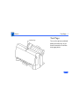
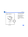
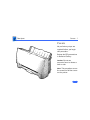
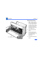
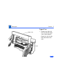
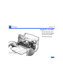
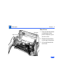
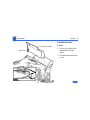
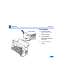
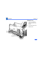
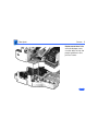
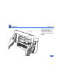
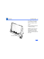
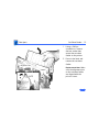
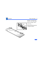
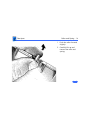
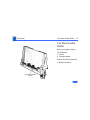
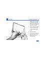
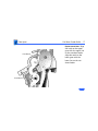
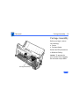
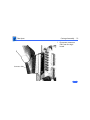
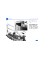
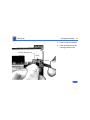
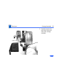
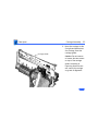
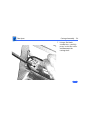
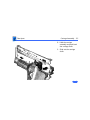
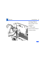
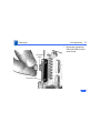
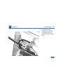
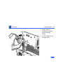
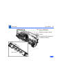
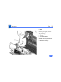
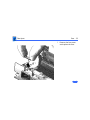
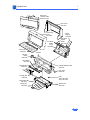
K Service Source
StyleWriter II
K Service Source
Basics
StyleWriter II
Basics
Test Page - 1
Online Key
Test Page
Turn on the printer and hold
down the online key for at
least 6 seconds or until the
test page prints.
Basics
Test Page - 2
The test page shows the ROM
revision and a test pattern.
Use the test pattern to
determine if the ink jets are
functioning properly. If
lines appear broken,
proceed to the “Printing”
topic in the Troubleshooting
chapter.
K Service Source
Specifications
StyleWriter II
Specifications
Characteristics - 1
Characteristics
Print Methods
Throughput
Serial bubble jet ink-on-demand
SHQ mode 124 cps (10 cpi)
HQ mode 173 cps (10 cpi)
HS mode 248 cps (10 cpi)
Print Head
1 by 64 nozzles
Print Head Life
Approximately 500 pages (normal mode)
Input Buffer
9K
Specifications
Graphics - 2
Graphics
Resolution
360 dpi (at best mode)
Specifications
Paper Handling - 3
Paper Handling
Paper
Size: LTR, LGL, A4
Weight: 16–24 lb.
Capacity: 100 sheets (A4, LTR)
Envelopes
Size: Commercial number 10 size only (4.1 in. by 9.5 in)
Capacity: 10 envelopes
Transparencies
Coated transparencies, or most inkjet transparencies
Specifications
Ink Cartridges - 4
Ink Cartridges
Type
Ink cartridge
Ink Color
Black
Ink Amount
Approximately 28 g (per cartridge)
Life
Approximately 500 pages
Specifications
Environmental - 5
Environmental
Acoustic Noise Level
Approximately 40 dB (reference level)
Temperature
41–95° F (5–35° C)
Humidity
10–90% (no condensation)
Specifications
Electrical - 6
Electrical
Power Source
Power Consumption
U.S./Canada: 120 VAC, 60 Hz, 0.36 A
U.K./Australia: 240 VAC, 50 Hz, 24 W
Europe: 220 VAC, 50 Hz, 24 W
48 W maximum
Specifications
Physical - 7
Physical
Dimensions
Weight
Height: 6.8 in. (173 mm)
Width: 13.7 in. (347 mm)
Depth: 7.6 in. (193.5 mm)
Approximately 6 lb. (3 kg)
K Service Source
Troubleshooting
StyleWriter II
Troubleshooting
General/ - 1
General
The Symptom Charts included in this chapter will help you
diagnose specific symptoms related to your product. Because cures
are listed on the charts in the order of most likely solution, try
the first cure first. Verify whether or not the product continues to
exhibit the symptom. If the symptom persists, try the next cure.
(Note: If you have replaced a module, reinstall the original module
before you proceed to the next cure.)
If you are not sure what the problem is, or if the Symptom Charts
do not resolve the problem, refer to the Flowchart for the product
family.
For additional assistance, contact Apple Technical Support.
Troubleshooting
Symptom Charts /Preliminary Checks - 2
Symptom Charts
Preliminary Checks
Computer cannot find
printer
1
2
3
4
Verify that StyleWriter II driver is installed.
Verify that Chooser and Control Panel settings are correct.
Verify that serial cable is connected.
Replace serial cable.
No lights or
movement
1
2
Verify that printer is turned on and plugged into wall socket.
Replace fuse.
Print quality
problems
1
2
3
4
Verify that paper is correct weight.
Purge ink cartridge.
Replace ink cartridge.
Replace printer.
Troubleshooting
Mechanical problems
Symptom Charts /Preliminary Checks - 3
1
2
3
4
Verify that paper is correct weight.
Clear paper jam.
Verify that cut sheet feeder aligns with printer.
Replace printer.
Troubleshooting
Symptom Charts /Status Light - 4
Status Light
No status lights
1
2
3
Error light on
1
2
3
4
Replace fuse.
Verify that operation cable is securely connected to logic
board.
Replace printer.
Printer is out of paper; add paper.
Check for paper jam; remove jam and then press power
switch.
Check for carriage jam.
Replace printer.
Troubleshooting
Symptom Charts /Printing - 5
Printing
No printing
1
2
3
4
5
6
Garbled printing
1
2
3
4
Verify that interface cable between printer and computer is
tightly connected.
Make sure printer is selected in Chooser.
Purge ink cartridge.
Replace ink cartridge.
Verify that right-margin sensor is seated correctly.
Replace printer.
Verify that interface cable between printer and computer is
tightly connected.
Purge ink cartridge.
Replace ink cartridge.
Replace printer.
Troubleshooting
Overprinting
Symptom Charts /Printing - 6
1
2
3
Image too light or too
dark
White lines in
printing
1
2
3
Verify that program being used is set for correct line
spacing and line length.
Verify that correct printer driver is installed.
Replace printer.
4
Purge ink cartridge.
Use 16–24 lb. cotton bond paper.
Verify that forms thickness lever is set correctly (up for
standard paper and down for envelopes, transparencies,
labels, and heavy paper).
Replace ink cartridge.
1
2
3
Purge ink cartridge.
Replace ink cartridge.
Replace printer.
Troubleshooting
Page prints off
center; images are out
of place
Symptom Charts /Printing - 7
1
2
3
4
5
Use 16–24 lb. cotton bond paper.
Verify that sheet feeder holds no more than 50 sheets.
Verify that paper is inserted properly.
Verify that margins in document and paper size in Page Setup
are set correctly.
Replace printer.
Ink appears on back of
paper
1
2
3
Clean platen with soft, dry cloth.
Clean platen rollers.
Replace printer.
Image wavy, splotchy,
or distorted
1
2
3
Purge ink cartridge.
Replace ink cartridge.
Replace printer.
Troubleshooting
Symptom Charts /Carrier Movement - 8
Carrier Movement
Erratic carrier
motion
Replace printer.
Power light is on;
carrier does not move
1
2
Printer does not
perform self-test;
ready light is on
Replace printer.
Carrier grinds, hums
loudly, or locks
1
2
Make sure carrier area is clear of obstructions.
Replace printer.
Verify that right-margin sensor is seated correctly.
Replace printer.
Troubleshooting
Symptom Charts/Paper Feed - 9
Paper Feed
No paper feed
1
2
3
4
Verify that cut sheet feeder aligns with printer.
Release paper pressure plate on cut sheet feeder.
Make sure paper path is clear of obstructions.
Replace printer.
Grinding during paper
feed
1
2
Make sure paper path is clear of obstructions.
Verify that forms thickness lever is set correctly (up for
standard paper and down for envelopes, transparencies,
labels, and heavy paper).
Verify that cut sheet feeder aligns with printer.
Replace printer.
3
4
Troubleshooting
Symptom Charts /Paper Feed - 10
Paper feed
difficulties: binding,
tearing
1
Envelope feed
problems
1
2
3
4
5
6
2
Verify that forms thickness lever is set correctly (up for
standard paper and down for envelopes, transparencies,
labels, and heavy paper).
Make sure paper path is clear of obstructions.
Verify that paper is inserted properly.
Use 16-24 lb. cotton bond paper.
Verify that cut sheet feeder aligns with printer.
Replace printer.
When printing envelopes: (a) adjust paper thickness lever,
(b) do not run cut sheets and envelopes in same print job,
and (c) reset paper thickness lever when finished printing
envelopes.
Replace printer.
Troubleshooting
Symptom Charts /Miscellaneous - 11
Miscellaneous
Operations panel
buttons don’t work
1
Software-specific
problem
1
2
2
Verify that operations panel cable is securely connected to
logic board and operations panel.
Replace printer.
Verify that software is known-good.
Verify that software is compatible with TrueType fonts.
(Check your software application manual.)
K Service Source
Take Apart
StyleWriter II
Take Apart
Covers - 1
Covers
No preliminary steps are
required before you begin
this procedure.
Review the ESD precautions
in Bulletins/Safety.
Caution: Do not use
excessive force to release a
latch or tab.
Note: This procedure covers
the removal of all the covers
on the printer.
Take Apart
Covers - 2
Front Access Cover
1
2
Arm
3
Arm
Front Access Cover
4
Note: The front access
cover is held in place by
two arms that function
as hinges. Plastic tabs at
the end of the arms fit
into knobs on the inside
of the upper case.
Open the front access
cover.
Press the end of each
arm inward and free the
arm tabs from the
upper case.
Lift off the front access
cover.
Take Apart
Covers - 3
Upper Case
1
Upper Case
Latch
Release the right side
latch and lift the upper
case a short distance.
Repeat for the left side
latch and remove the
case.
Take Apart
Covers - 4
Output Tray Assembly
1
0utput Tray
Pull out the tray until
the two tabs rest against
the stops. Press down
and remove the tray.
Take Apart
Covers - 5
Rear Cover
Top Latch
1
Rear Cover
2
3
Bottom Latch
Press out the two latches
on the bottom of the
printer and press up on
the rear cover.
Release the two latches
on the top of the printer.
Lift up and remove the
rear cover.
Take Apart
Covers - 6
Cut Sheet Feeder
Side Latch
Cut Sheet Feeder
Cover
1
2
Front Latch
Front Latch
Press in the front latch
and release the side
latch.
Pull back and remove the
cover.
Take Apart
Covers - 7
Paper Support
Paper Support
1
2
3
Pull out the paper
support until it rests
against the stops.
Push the support
forward and disconnect
the latches.
Slide out the paper
support.
Take Apart
Covers - 8
Bottom Cover
1
2
Front
Latch
Bottom Cover
Front Latch
Using a screwdriver,
push out the two front
latches.
Pull up and remove the
bottom cover.
Take Apart
Covers - 9
Replacement Note: Make
sure the bottom cover
circular tabs fit into the
proper position in the
printer frame.
Take Apart
Covers - 10
Latch
On/Off Button
Replacement Note: Make
sure the latch on the
upper case engages the
on/off button on the logic
board.
Take Apart
Cut Sheet Feeder - 11
Cut Sheet Feeder
Before you begin, remove
covers.
Review the ESD precautions
in Bulletins/Safety.
Caution: Do not get the ink
on your hands or clothes.
Although the ink is water
soluble, it contains dyes that
will stain.
Cut Sheet Feeder
Take Apart
Cut Sheet Feeder - 12
1
2
Alignment Pin
Latch
Using a Phillips
screwdriver, remove
the two screws that
secure the cut sheet
feeder to the printer.
Press in the latch and
remove the cut sheet
feeder.
Replacement Note: Make
sure the alignment pins
on the cut sheet feeder
are aligned with the
printer frame.
Take Apart
Roller and Spring - 13
Roller and Spring
Before you begin, remove
front cover.
Review the ESD precautions
in Bulletins/Safety.
Front Cover
Take Apart
Roller and Spring - 14
1
2
Push the roller forward
slightly.
Carefully lift up and
remove the roller and
spring.
Take Apart
Cut Sheet Feeder Roller - 15
Cut Sheet Feeder
Roller
Before you begin, remove
the following:
• Covers
• Cut sheet feeder
Review the ESD precautions
in Bulletins/Safety.
Cut Sheet Feeder
Roller
Take Apart
Cut Sheet Feeder Roller - 16
1
2
3
Roller
Caution: When the roller
is removed, the feeder
gear is loose. Remove the
roller slowly so that the
gear will not fly off.
Press in the two latches
on the cut sheet feeder
roller and push out the
roller.
Remove the gear.
Lift up on one end of the
roller and remove the
other end from the
mounting hole.
Take Apart
Line/Notch
Line/Notch
Cut Sheet Feeder Roller - 17
Replacement Note: Align
the notch on the upper
gear with the upper line
on the cut sheet feeder.
Align the notch on the
lower gear with the
lower line on the cut
sheet feeder.
Take Apart
Carriage Assembly - 18
Carriage Assembly
Before you begin, remove
the following:
• Covers
• Cut sheet feeder
Review the ESD precautions
in Bulletins/Safety.
Caution: To prevent the
print nozzles from clogging,
do not touch or wipe them.
Carriage Assembly
Take Apart
Carriage Assembly - 19
1
Connector CNH
Disconnect connector
CNH from the logic
board.
Take Apart
Carriage Assembly - 20
2
Remove the plastic
ribbon cable and cable
holder.
Replacement Note: Make
sure the ribbon cable
holes are mounted on the
two tabs on the inside of
the ribbon cable holder.
Take Apart
Carriage Assembly - 21
3
4
Carriage Release Clip
Latch
Latch
Press in the two latches.
Push up and remove the
carriage release clip.
Take Apart
Carriage Assembly - 22
5
Shaft Clip
Carefully remove the
shaft clips from each
side of the carriage
assembly.
Take Apart
Carriage Assembly - 23
6
Carriage Guide
Move the carriage to the
far right and disconnect
the carriage from the
carriage guide.
Caution: Do not remove
or loosen the two screws
on top of the carriage
guide. Loosening or
removing these screws
will cause the carriage
to go out of alignment.
Take Apart
Carriage Assembly - 24
7
Using a flat-blade
screwdriver, carefully
press in the idler roller
and disconnect the
carriage belt.
Take Apart
Carriage Assembly - 25
8
9
Hold the carriage
assembly and push back
the carriage shaft.
Slide out the carriage
shaft.
Take Apart
Carriage Motor - 26
Carriage Motor
Carriage
Motor
Before you begin, remove
the following:
• Covers
• Cut sheet feeder
Review the ESD precautions
in Bulletins/Safety.
Take Apart
Carriage Motor - 27
1
Connector
CNCR
Connector CNH
Disconnect connectors
CNH and CNCR from the
main board.
Take Apart
Carriage Motor - 28
2
Using a flat-blade
screwdriver, press in
the idler roller and
disconnect the carriage
belt.
Take Apart
Carriage Motor - 29
3
4
Using a Phillips
screwdriver, remove
the two mounting
screws.
Lift up and pull out the
carriage motor.
Take Apart
Eject Roller - 30
Eject Roller
Before you begin, remove
covers.
Review the ESD precautions
in Bulletins/Safety.
Eject Roller
Take Apart
Eject Roller - 31
1
Grasp one end of the
roller, press it firmly
to the side, and snap the
roller out of the
mounting holes.
Take Apart
Fuse - 32
Fuse
Before you begin, remove
the following:
• Covers
• Cut sheet feeder
Fuse
Review the ESD precautions
in Bulletins/Safety.
Take Apart
Fuse - 33
1
Remove the fuse cover
and replace the fuse.
K Service Source
Exploded View
StyleWriter II
Exploded View
1
Whole Unit
110V 661-0785
220V 661-1010
Rear Cover
922-0184
Upper Case
Cover
922-0185
Cut Sheet
Feeder
Cover
922-0188
Paper
Support
922-0189
Cut Sheet
Feeder
Roller
922-0192
Front Cover
922-0186
Chassis*
Carriage
Motor
922-0195
Eject Roller
922-0191
Carriage Belt
922-0193
Carriage Release Clips
922-0197
Clip, Shaft
922-0196
Carriage Unit
922-0194
Feet, Bottom
922-0182
Output Tray
922-0187
Fuse
125 V 922-0180
250 V 922-0181
BottomCase
922-0198