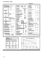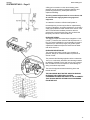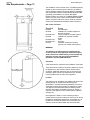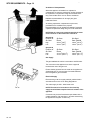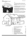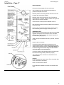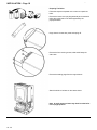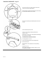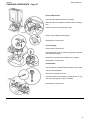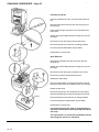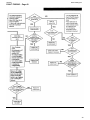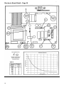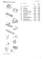
1
Please leave these Instructions with the User
Baxi Genesis
Gas Fired Wall Mounted Combination Boiler
Natural Gas, Propane & Butane
Comp No. 236463 - 10/96
Baxi Genesis 80 – G.C.No 47 077 01
Baxi Genesis 96 – G.C.No 47 077 02
Installation
and
Servicing
Instructions
42 - 43
Genesis
Baxi Heating Ltd.
Baxi Heating Ltd is one of the leading manufacturers of
domestic heating products in the U.K.
Our first priority is to give a high quality service to our
customers. Quality is built into every Baxi product -products
which fulfil the demands and needs of consumers, offering
choice, efficiency and reliability.
To keep ahead of changing trends, we have made a
commitment to develop new ideas using the latest
technology - with the aim of continuing to make the products
that customers want to buy.
Baxi is also the largest manufacturing partnership in the
country. Everyone who works at the company has a
commitment to quality because, as shareholders, we know
that satisfied customers mean continued success.
We hope you get a satisfactory service from Baxi. If not,
please let us know
Baxi is a BS-EN ISO 9002 Accredited Company
44 - 45
Genesis
Baxi Heating Ltd.
Contents – Page 3
Introduction
General Layout
Appliance Operation
Technical Data
General Dimensions & Fixings
System Details
Site Requirements
Installation
Commissioning the Appliance
Servicing The Appliance
Changing Components
Fault Finding
Short Parts List
PAGE 4
PAGE 5
PAGE 6
PAGE 7-8
PAGE 9
PAGE 10-12
Central Heating circuit
Bypass
System Control
System Filling & Pressurising
Pressure Vessel
Pressure Relief Valve
Domestic Hot Water Circuit
Showers
Hard Water Areas
PAGE 13-16
B.S. Codes of Practice
Clearances
Location
Ventilation of Compartments
Gas Supply
Electrical Supply
Flue
Terminal Guard
PAGE 17-24
Initial Preparation
Flushing
Preparing the Boiler
Fitting the Boiler
Fitting the Flue
Making the Electrical Connections
PAGE 26
PAGE 27
PAGE 28-41
Pressure Switch
Fan
Gas Valve Solenoids
Domestic Hot Water Heat Exchanger
Heat Exchanger
Pump
PCB & Spark Generator
Thermistors
Safety Thermostat
Expansion Vessel
Pressure Relief Valve
Pressure Gauge
Flow Switches
Flame Sensing Probe
Spark Electrode
Injector Manifold
3-Way Valve
Water Filters
Automatic Air Vent
Flow Regulator
PAGE 42-50
PAGE 51
3
Genesis
Baxi Heating Ltd.
Introduction – Page 4
Description
The Baxi Genesis is a fully automatic gas fired wall mounted
combination boiler. It is room sealed and fan assisted, and
will serve central heating and mains fed domestic hot water.
Genesis 80
The boiler is preset to give a maximum output of 23.25 kW
(79,347 Btu/hr) for both hot water and central heating
modes.
Genesis 96
The boiler is preset to give a maximum output of 28.0 kW
(95,555 Btu/hr) for both hot water and central heating
modes.
It is designed for use on natural gas (G20). Using the
conversion kit it can be used on LPG (Propane G31 or
Butane G30).
The boiler is suitable for use only on fully pumped sealed
heating systems. Priority is given to domestic hot water.
The appliance data badge is positioned on the electrical box
behind the outer case.
A label on the user door panel gives details of the model,
serial number and Gas Council number.
Optional Extras
KIT
Flue extension 1 M (Use two kits for 2M etc.)
Flue Extension 0.25M
Flue Extension 0.5M
DHW Expansion Vessel Kit
Wall liner/internal fixing
Programmable room thermostat 24 hr.
Programmable room thermostat 7 day
Integral 7 day Electronic Timer Kit
Integral 12 hr. AM/PM 8ectro-Mechanical
Timer Kit
80 LPG Conversion - Propane & Butane
96 LPG Conversion - Propane & Butane
Flue bend - 45º
Flue bend - 90º
Vertical Flue Equipment See Installer’s Guide or Notes For Guidance
44 - 45
PART No
236439
238605
238604
238395
236441
236254
238326
238399
238398
235983
237474
236467
236466
Genesis
Baxi Heating Ltd.
General Layout – Page 5
1
Chassis with Expansion Vessel
2
Combustion Box
3
Fan Assembly
4
Primary Heat Exchanger
5
Combustion Chamber
6
Burner Assembly and Electrodes
7
Gas Valve Assembly
8
Automatic Air Seperator and Vent
9
Flow Switch Heating Circuit
10
Flow Switch DHW Circuit
11
Circulation Pump
12
Electrical Box
13
Safety Thermostat
14
By-Pass Valve
15
DHW Thermostat Sensor
16
CH Thermostat Sensor
17
Three Way Valve
18
DHW Plate Heat Exchanger
19
Selector Switch On-Off
20
DHW Temperature Adjustment
21
Heating Temperature Adjustment
22
Heating Temperature Indicator
23
Green Light - Power On
24
Orange Light - Boiler On
25
Red Light - Flame Failure
26
Flame Failure Reset Button
27
Pressure Gauge
28
Pressure Switch
29
Isolating Valves
30
Optional Integral Timers
5
Genesis
Baxi Heating Ltd.
Appliance Operation – Page 6
CENTRAL HEATING MODE
With a demand for heating the pump (11) circulates water
through the primary circuit. At a flow rate of approximately
250 I/hr the central heating flow switch (9) operates,
commencing the ignition sequence.
The main burner (6) ignites at 1/3 rate then switches to full
gas rate. The gas valve (7) controls the gas rate “HIGH LOW” to maintain the heating temperature measured by the
thermostat sensor (16).
When demand is satisfied the burner is extinguished, the
pump continues to run. The duration of each OFF cycle is 3
minutes before re-lighting automatically. Each ON cycle
commences with a 45 second duration at third gas rate
before switching to full rate if necessary.
On completion of a heating period the pump will continue to
run for a period of 3 minutes (PUMP OVERRUN).
DOMESTIC HOT WATER MODE
Priority is given to hot water supply. A demand at a tap or
shower will override any central heating requirement.
The flow of cold water will operate the DHW flow switch (10)
which requests the 3 way valve (17) to change position to
allow the pump (11) to circulate the primary water through
the secondary DHW heat exchanger (18).
The appliance-will light automatically and the temperature of
the domestic water is controlled by the thermostat sensor
(15).
When the hot water demand ceases the burner will
extinguish and for a period of 3 minutes the appliance
remains ready in the DHW mode before returning to the
central heating mode.
44 - 45
Genesis
Baxi Heating Ltd.
Technical Data – Page 7
GENESIS 80
7
Genesis
Baxi Heating Ltd.
Technical Data – Page 8
GENESIS 96
44 - 45
Genesis
Baxi Heating Ltd.
General Dimensions and Fixings – Page 9
9
Genesis
Baxi Heating Ltd.
System Details – Page 10
The Genesis Combination Boiler is a ‘Water Byelaws
Scheme - Approved Product’.
To comply with the Water Byelaws your attention is
drawn to the following installation requirements and
notes (IRN).
1)
2)
3)
IRN 001 - See text of entry for installation requirements
and notes.
IRN 116- Byelaw 90 and 91.
IAN 302 - Byelaw 14.
Reference to the WRc publications, ‘Water fittings and
materials directory’ and ‘Water supply byelaws guide’ give
full details of byelaws and the IRNs.
Central Heating Circuit
The appliance is suitable for fully pumped SEALED
SYSTEMS ONLY.
All systems should be thoroughly flushed prior to
connection of the appliance. If the installation is on an
existing sealed system, or a modified open system, it is
particularly important to flush preferably using an
appropriate descaling/flushing agent.
Where used, corrosion inhibitors, flushing agents/descalers
should be approved and suitable for all system metals.
BYPASS
The appliance has an integral pre-set bypass, therefore no
external bypass on the system is required. TRV’s can be used on all radiators.
SYSTEM CONTROL
Operation of the system under control of the boiler
thermostat only does not produce the best results. The
heating system should include a control system. This should
comprise of at least a single channel timer.
Integral Single Channel Timer Kits are available as optional
extras.
For optimum operating conditions and best economy the
fitting of a programmable thermostat is recommended.
Programmable thermostats - the ‘Baxi Genesis
Controllers’ are available as an optional extra.
44 - 45
Genesis
Baxi Heating Ltd.
SYSTEM DETAILS – Page 11
A filling point connection on the central heating return
pipework must be provided to facilitate initial filling and
pressurising and also any subsequent water loss
replacement/refilling.
The filling method adopted must be in accordance with
all relevant water supply byelaws using approved
equipment.
Your attention is drawn to: IRN 302 and Byelaw 14.
Unvented primary circuits may be filled or replenished by
means of a temporary connection between the circuit and a
supply pipe provided a ‘Listed’ double check valve or some
other no less effective backflow prevention device is
permanently connected at the inlet to the circuit and the
temporary connection is removed after use.
PRESSURE VESSEL
The appliance expansion vessel is pre-charged to 0.7 bar
(10 lb/in2). Therefore, the minimum cold fill pressure is 0.7
bar. The vessel is suitable for correct operation for system
capacities up to 125 litres (27.5gal). For greater system
capacities an additional expansion vessel must be fitted refer to BS 7074 Pt 1.
PRESSURE RELIEF VALVE
The pressure relief valve is set at 3 bar, therefore all
pipework, fittings etc should be suitable for pressures in
excess of 3 bar.
The pressure relief discharge pipe should be not less than
15mm, run continuously downward, and discharge outside
the building, preferably over a drain, and in such a manner
that no hazard occurs to occupants or cause damage to
wiring or electrical components.
The end of the pipe should terminate facing down and
towards the wall.
THE DISCHARGE MUST NOT BE ABOVE A WINDOW,
ENTRANCE OR OTHER PUBLIC ACCESS.
CONSIDERATION MUST BE GIVEN TO THE POSSIBIUTY
THAT BOILING WATER /STEAM COULD DISCHARGE
FROM THE PIPE.
11
Genesis
Baxi Heating Ltd.
SYSTEM DETAILS – Page 12
Domestic Hot Water Circuit
All DHW circuits, connections, fittings etc should be
fully in accordance with relevant standards and water
supply bye-laws.
Your attention is drawn to: IRN 116 and Byelaw 90 and 91.
Sealed primary circuits and / or secondary hot water
systems shall incorporate a means for accommodating the
thermal expansion of water to prevent any discharge from
the circuit and / or system except in an emergency situation.
When the system includes any device which prevents water
expanding back towards the supply (check valve, loose
jumpered stopcock; water meter, water treatment device),
then an expansion vessel must be fitted e.g. (Zilmet 160ml,
R ½ 15bar).
To comply with Byelaw 91,a check valve must also be fitted
on the supply as shown, to ensure efficient operation and
also to prevent the reverse flow of hot water into the supply
pipe.
IF THE HOT WATER EXPANSION IS NOT PROVIDED
FOR, THEN HIGH PRESSURES CAN DEVELOP WHICH
MAY RESULT IN DAMAGE TO FITTINGS AND DEVICES
ON THE SYSTEM.
The appliance maximum working mains pressure is 10 bar
(150 lb/in2), therefore all pipework, connections, fittings etc
should be suitable for pressures in excess of 10 bar: A
pressure reducing valve must be fitted for pressures in any
outlet fittings, such as a shower excess of 10 bar: The
manufacturer of valve, may require a lower maximum
pressure. The pressure reduction must take account of all
fittings connected to the DHW system.
SHOWERS
If a shower control is supplied from the appliance it should
be of the thermostatic or pressure balanced type.
Thermostatic type shower valves provide the best comfort
and guard against water at too high a temperature. Existing
controls may not be suitable - refer to the shower
manufacturers.
HARD WATER AREAS
If the area of the installation is recognised as a HARD
WATER AREA then a suitable device should be fitted to
treat the mains water supply to the appliance.
44 - 45
Genesis
Baxi Heating Ltd.
Site Requirements – Page 13
The installation must be carried out by a CORGI Registered
Installer or other competent person and be in accordance
with the relevant requirements of GAS SAFETY (Installation
and Use) REGULATIONS, the BUILDING REGULATIONS
(Scotland) (Consolidation), the LOCAL BUILDING
REGULATIONS, the current I.E.E. WIRING REGULATIONS
and the bye laws of the LOCAL WATER UNDERTAKING.
(Where no specific instruction is given reference should be
made to the relevant British Standard Codes of Practice.)
B.S. Codes of Practice
Standard
Scope
BS 6891
BS 5546
Gas Installation.
Installation of hot water supplies for
domestic purposes.
Forced circulation hot water systems.
Installation of gas fired hot water
boilers.
Flues.
Air supply
Expansion vessels and ancillary
equipment for sealed water systems.
BS 5449 Part 1
BS 6798
BS 5440 Part 1
BS 5440 Part 2
BS 7074
WARNING
The addition of anything that may interfere with the
normal operation of the appliance without the express
written permission of Baxi Heating could invalidate the
appliance warranty and infringe the GAS SAFETY
(Installation and Use) REGULATIONS.
Clearances
A flat vertical area is required for the installation of the boiler.
These dimensions include the necessary clearances around
the appliance for case removal, spanner access and air
movement. Additional clearances may be required for the
passage of pipes around local obstructions such as joists
running parallel to the front face of the appliance.
Location
The appliance may be fitted to any suitable wall with the flue
passing through an outside wall and discharging to
atmosphere in a position permitting satisfactory removal of
combustion products and providing an adequate air supply.
The appliance should be fitted within the building unless
otherwise protected by a suitable enclosure ie. garage or
outhouse. (The appliance may be fitted inside a cupboard see page 14).
If the appliance is fitted in a room containing a bath or
shower reference must be made to the Current I.E.E. Wiring
Regulations and Building Regulations. If the appliance is to
be fitted into a building of timber frame construction then
reference must be made to British Gas document DM2.
13
Genesis
Baxi Heating Ltd.
SITE REQUIREMENTS – Page 14
Ventilation of Compartments
Where the appliance is installed in a cupboard or
compartment, air vents are required (for cooling purposes) in
the cupboard or compartment at high and low level which
may communicate with a room or direct to outside air.
Detailed recommendations for air supply are given
in BS 5440: Part 2.
An existing cupboard or compartment may be used,
provided that it is modified for the purpose.
Recommendations for air supplies and details of -essential
cupboard compartment design are given In BS 5440:Part2.
NOTE:-Both air vents must communicate with the same
room or both be on the same wall to outside air.
Genesis 80
Position of
Air Vent
Air from
Room
Air direct
from Outside
Position of
Air Vent
Air from
Room
Air direct
from Outside
High
Low
311cm2 (48.2 in2)
311cm2 (48.2 in2)
156cm2 (24.1 in2)
156cm2 (24.1 in2)
High
Low
257cm2 (39in2)
257cm2 (39in2)
128cm2 (19.5in2)
128cm2 (19.5in2)
Genesis 96
Gas Supply
The-gas installation should be in accordance with BS 6891.
The connection to the appliance is a 22mm copper tail
located at the rear of the gas cock.
Ensure that the pipework from the meter to the appliance is
of adequate size. Do not use pipes of a smaller diameter
than the appliance gas connection.
Electrical Supply
External wiring must be correctly earthed, polarized and in
accordance with current I.E.E. Wiring Regulations.
The mains supply is 230V - 50Hz fused at 3A.
NOTE:-The method of connection to the electricity
supply must facilitate complete electrical isolation of the
appliance.
Connection may be via a fused double-pole isolator with a
contact separation of at least 3mm in all poles and servicing
the appliance and system controls only.
44 - 45
Genesis
Baxi Heating Ltd.
SITE REQUIREMENTS – Page 15
Flue
An internal fitting kit is available for installations where the
flue terminal is inaccessible from the outside. -(Part No
236441). This is available from merchants or direct from Baxi
free of charge.
The following guidelines indicate the general requirements
for siting balanced flue terminals. Recommendations for
flues are given in BS 5440 Pt.1.
If the terminal is fitted within 1 metre (39 in) of a plastic
gutter, within 500mm (19 ½ in) of a painted eave or a
painted gutter, an aluminium shield of at least 1 metre (39 in)
long should be fitted to the underside of the gutter or painted
surface. An air space of 5mm (3/16 in) should be left
between shield and gutter.
If the terminal discharges onto a pathway or passageway,
check that combustion products will not cause a nuisance
and that the terminal will not obstruct the passageway.
Terminal Position with Minimum Distance
A
B
C
D
E
F
G
H
I
J
K
L
Directly below an openable window or other
opening. e.g. an air brick.
Below gutters.
Below eaves, soil pipes or drain pipes.
Below balconies or car port roof
From vertical drain pipes and soil pipes.
From internal or external corners.
Above ground, roof or balcony level.
From a surface facing a terminal.
From a terminal facing a terminal.
Vertically from a terminal on the same wall.
Horizontally from a terminal on the same wall.
For an opening in a car port (e.g. door, window)
into a dwelling.
(mm)
300
25
75
200
75
25
300
600
1200
1500
300
1200
15
Genesis
Baxi Heating Ltd.
SITE REQUIREMENTS – Page 16
Flue Dimensions
The standard flue supplied with the appliance is suitable for
use with flue lengths between 220mm (8 21/32in) and
610mm (24in).
TOTAL FLUE LENGTH PERMISSIBLE IS:
3 METRES MAX.
Terminal Guard
When codes of practice dictate the use of terminal guards,
they can be obtained from most Plumbers and Builders
Merchants nationwide.
When ordering a terminal guard, quote the appliance model
number.
The guard manufacturers listed below can be contacted for
terminal sizes and guard model numbers.
Tower Flue Components Ltd.,
Tower House,
Vale Rise,
Tonbridge,
Kent.
Tel: 01732 351555.
Quinnell, Barrett & Quinnell,
884 Old Kent Road,
London, SE15 1NL
Tel: 0171 639 1357.
FIXING
The flue terminal guard should be positioned centrally over
the terminal and fixed as illustrated.
44 - 45
Genesis
Baxi Heating Ltd.
Installation – Page 17
Initial Preparation
Remove the fixing template from the small carton.
After considering the site requirements (see page 13)
position the template on the wall.
Mark the position of the fixing holes for the two hooks. Use
the upper two holes where possible.
Mark the centre of the flue hole (rear exit). For side exit,
mark as shown. If required, mark the position of the gas and
water pipes. Remove the template.
Cut the hole for the flue (minimum diameter 107mm).
Drill and plug the wall as previously marked. Secure the two
hooks to the wall.
Insert the two outer support bracket fixing screws, leaving
them sufficiently proud to engage in the keyhole slots.
GENESIS 96 ONLY
Before fixing the support bracket to the wall remove the blue
regulator unit from the inlet connection of the cold water
isolating valve. Replace with the red regulator supplied in
the contents kit (See page 41).
Attach the support bracket and ensuring it is level, secure to
the wall.
Insert the two inner screws.
Connect the gas and water pipes to the valves on the
support bracket using the copper tails supplied. Ensure the
sealing washers are fitted correctly. (The rubber washer is
for use on the gas connection only. The fibre washers
are for the water circuit connections.)
Connect a pressure relief discharge pipe to the safety valve
tail routed to discharge safely outside the property.
The symbols for each connection are embossed on the
support bracket.
Flushing
Flush thoroughly (see system notes). There is a plastic tube
in the contents kit to aid flushing.
Insert in to valve outlet as shown.
Fit the water filter supplied in the kit to the cold water inlet
valve.
17
Genesis
Baxi Heating Ltd.
INSTALLATION – Page 18
Preparing The Boiler
Follow the sequence depicted on the carton to unpack the
boiler.
Remove the lower cover poly bag assembly and contents kit
before laying the boiler on its back supported by the
polystyrene block.
Hinge down the lower door panel and spring off.
Remove the four securing screws, slide and lift away the
outer case.
Remove the sealing plugs from the copper bends.
Stand the boiler on its base on the carton sleeve.
Note: A small amount of water may drain from the boiler
in the upright position.
44 - 45
Genesis
Baxi Heating Ltd.
INSTALLATION – Page 19
Fitting The Boiler
Lift the boiler using the lower edge of the combustion box
and the hand holds in the chassis.
Place boiler on the support bracket, slide back then lift to
engage on top hooks.
Hinge down the electrical box to gain access to the
connections between boiler and valves.
At both sides push in the two tabs - hinge box down by
rotating.
Check the inlet water filter is fitted (F).
Make the gas connection first (G). This will centralise the
boiler.
Insert the sealing washers between the valve outlet face and
the flange on the copper bends. The rubber washer is for
use on the gas connection only. The fibre washers are
for the water circuit connections.
Tighten the connections.
19
Genesis
Baxi Heating Ltd.
Fitting The Flue – Page 20
HORIZONTAL FLUE
The standard flue supplied with the appliance is suitable for
lengths 220mm minimum to 610mm maximum.
Rear flue: maximum wall thickness - 490mm.
Side flue,
(left or right): maximum wall thickness - 477mm.
If fitting the optional Intel fitting kit, flue extension kit or
elbows refer to the instructions provided with the kits.
Place the flue elbow on to the flue connection, with the
outlets facing the wall opening.
Measure the distance from the outside wall face to the
elbow. This is to be dimension (X)
Mark dimension (X) on the plastic air duct measuring from
the flue terminal as shown.
Measure the length of waste material from the air duct.
Take the aluminium flue duct and mark off this length. from
the plain end. Do not cut the flared end.
The required dimension of the flue duct is (X)+55mm.
IMPORTANT:
Check your measurements before cutting.
Cut the ducts to size.
44 - 45
Genesis
Baxi Heating Ltd.
Fitting The Flue – Page 21
Slide the rubber seal and clip over the air duct.
Engage the flared end of the flue duct onto the flue elbow.
Insert the flue duct into the air duct and engage it in the
terminal.
Slide the rubber sleeve over the joint between the air duct
and elbow.
Align the clip over the rubber seal. For neatness the screws
on the clip flange should be below the air duct if possible,
providing they remain accessible.
Secure the clip.
Place the flue gasket on the boiler flue connection.
Slide the flue ducts through the hole in the wall.
Engage the elbow flange and collar on to the flue connection
on top of the boiler. Align the cut-out in the collar with the
two sampling points. Secure with the four screws.
Make good between the wall and air duct outside the
building.
Fit the circular flue trim outside if required. Fit a terminal
guard if necessary (see page 16).
VERTICAL FLUE
Only a flue approved with the Baxi Genesis can be used.
For information on vertical flues consult the Genesis Installer
Guide or Notes for Guidance supplied with the vertical flue
pack.
21
Genesis
Baxi Heating Ltd.
Making The Electrical Connections – page 22
The electrical connections are on the right hand side of the
unit.
Undo the screws securing the small cover and remove the
cover.
Undo the screw securing the right hand cable clamp and
hinge up.
If fitting an integral timer kit please refer to kit
instructions at this stage, paying particular attention to
voltage requirements.
Route the incoming electrical cable/s over the top edge of
the support bracket. This will prevent damage to the
cables.
Lay the cable/s through the cable clamp to gauge the length
of cable required when the plug is connected.
Connect the (L) and (N) wires to the multipin plug, and the
earth wire to the grounding strip earth point.
The incoming cable/s can be routed through the cable clip at
the right hand side of the support bracket.
Check the electrical installation for earth continuity,
short-circuits, resistance to earth-correct polarity and
fuse failure.
CONNECTING AN EXTERNAL DEVICE
If a Baxi Genesis Controller (programmable thermostat)
is fitted refer to the instructions supplied with it.
To connect an external timer or room thermostat, remove the
link wire between terminals 1 & 2.
This connection delivers a low voltage switching signal to the
external controls, therefore only devices having voltage-free
switch contacts can be connected.
IMPORTANT: DO NOT CONNECT MAINS 230V TO
TERMINALS 1,2 OR 3- DAMAGE TO THE P.C.B. WILL
OCCUR.
44 - 45
Genesis
Baxi Heating Ltd.
Making The Electrical Connections – page 23
Fitting a Room Thermostat
A 2-wire or 3-wire low voltage thermostat can be fitted to
the Genesis plug.
To fit a 2-wire thermostat, remove link, and wire the
thermostat switch between positions 1 & 2.
To fit a 3-wire thermostat, remove link, and wire the
thermostat switch between positions 1 & 2. The anticipator
should be wired to position 3, as this provides a continuous
24V supply.
FITTING AN EXTERNAL TIMER
The external timer must have voltage-free switch contacts.
The timer switch must be connected between positions 1 &
2.
FITTING A FROST THERMOSTAT
The frost thermostat must have voltage-free switch
contacts.
If room and frost Thermostats, and an external timer are to
be incorporated in the control system they should be wired
as shown.
Connect the multipin plug into the socket on the
power board.
Secure the incoming cable/s with the cable damp and
replace the cover.
23
Genesis
Schematic Wiring Diagram – Page 24
44 - 45
Baxi Heating Ltd.
Genesis
Baxi Heating Ltd.
Illustrated Wiring Diagram – Page 25
25
Genesis
Baxi Heating Ltd.
Commissioning The Appliance – Page 26
Reference should be made to BS 5449 Section 5 when
commissioning the appliance.
Open the cold feed to the appliance.
Open all hot water taps to purge the DHW system.
Ensure that the filling loop is connected, and open the
heating flow and return valves on the appliance.
Open the automatic air vent. To help purge the primary
circuit turn the pump on & off several times by using the ONOFF selector switch.
Pressurise the system to 1.0 bar and disconnect the filling
loop.
Turn the gas supply on and purge the system according to
BS 6891.
Test for gas soundness.
Run the system and check the appliance for correct
operation. Check that there is an adequate gas supply
pressure at the gas tap (preferred minimum pressure is
19.5mbar).
Fitting The Outer Case
Locate lower cover below support bracket with isolating
valve spindles protruding through the slot.
Locate rear tabs through slots in support bracket -flange and
secure with the four-screws.
Fit lower hinged door by sliding the tabs into the cut-outs.
Hinge up, locating the two front tabs into the slots.
Remove the protective film from the outercase.
Position outercase on the chassis, ensuring that the two
slots in the top flange align with the tabs on the chassis.
Insert the four fixing screws into the base of the
chassis.
Replace the lower door panel by springing both ends on to
the pivots.
Hinge up to close.
Instruct the user in the operation of the appliance and
system, explaining the operational sequence.
Hand over these instructions and the users guide.
Emphasise the need for regular maintenance and returning
of the guarantee card.
44 - 45
Genesis
Baxi Heating Ltd.
Servicing The Appliance – Page 27
Annual Servicing
For reasons of safety and economy, it is recommended that
the appliance is serviced annually.
To measure the Co% and (Co2% content of the flue
products, remove the LH sample screw and insert a suitable
sampling probe.
Ensure that the appliance is cool.
Ensure that both the gas and electrical supplies to the
appliance are isolated.
Remove the outer case and lower door panel
(See Installation, p18).
Remove the screws securing the door panel.
Remove the door by lifting its lower edge forwards and
upwards, and disengage the lugs on the top corners.
Remove the screws securing the combustion box door.
Remove the door by lifting the lower edge forwards and
upwards through 90º.
Draw the door forwards.
Remove the two screws securing the injector manifold to gas
inlet pipe.
Remove the remaining four screws securing the manifold to
the burner.
Brush any deposits from the injectors. Do not use a pin or
wire to clean them.
Carefully brush the heat exchanger fins.
Brush the burner blades and venturis and combustion box
clean.
Reassemble in reverse order of dismantling and
recommission.
27
Genesis
Baxi Heating Ltd.
Changing Components – Page 28
Ensure that both the gas and electrical supplies to the
appliance are isolated.
Remove the outer case and door panel as described under
“Servicing the Appliance”.
Isolate the water circuits and drain as necessary.
There are five drain points:
1.
2.
3.
4.
5.
Central heating flow valve.
Domestic hot water outlet elbow.
Domestic cold water inlet valve.
Under three way valve.
Under automatic air vent.
Place tube on drain point to-drain water away from
electrics. Turn anticlockwise to open.
NOTE: When reassembling ‘O’ ring joints always place
the ‘O’ ring on the spigot
Where appropriate, after changing a component, recommission the appliance.
Pressure Switch
Remove the screw holding the pressure switch to the air box
back panel.
Draw the switch forwards, and noting the position of the
electrical connections and pressure pipes, remove them.
Reassemble. in reverse order. of dismantling, and in
accordance with the label on reverse of door panel.
Fan
Slacken the screw securing the fan and elbow seal.
Remove the screws holding the fan sealing plate to the
hood, and disengage the fan from the seal.
Draw the fan assembly forwards, and remove the electrical
connections. Note the position of the earth wire.
Remove the screws holding the sealing plate to the fan, and
remove the plate.
Fit the plate to the new fan, and reassemble in reverse order
of dismantling.
44 - 45
Genesis
Baxi Heating Ltd.
CHANGING COMPONENTS – Page 29
Gas Valve Solenoids
All three solenoids are permanently fixed to the valve cover
plate.
Remove the electrical connections, having noted their
positions. The wires are colour coded to each solenoid.
Remove the screws holding the plate to the valve body.
Remove the plate and gasket carefully to avoid losing the
three valves and springs.
Always fit a new gasket.
Reassemble in reverse order of dismantling.
Domestic Hot Water Heat Exchanger
Hinge down the electrical box.
Undo the screws holding the heat exchanger to the
manifolds.
Draw the heat exchanger carefully over the manifolds,
ensuring no wires are caught or damaged.
Remove and inspect the four lip seals, replace if necessary.
Replace in reverse order of dismantling, and re-commission,
ensuring that the off set location peg on the heat exchanger
is to the right.
29
Genesis
Baxi Heating Ltd.
CHANGING COMPONENTS – Page 30
Heat Exchanger
Remove the combustion box door as described under
“Servicing the Appliance”.
Undo the nut on the return pipe at the pump.
Remove the “R” clip on the flow pipe at the manifold.
Remove the clips securing the flow and return pipes to the
heat exchanger.
Ease the flow and .return pipes from the heat exchanger by
gently pulling downwards.
Pull the heat exchanger forwards and remove.
Reassemble in reverse order of dismantling, and recommission.
Pump
For ease of replacement fit a new pump head to the existing
housing.
A standard Grundfos UPS 15-50 pumphead is
interchangeable.
This must be switched to setting 3.
44 - 45
Genesis
Baxi Heating Ltd.
CHANGING COMPONENTS – Page 31
Pump (Head Only)
Hinge down the electrical box.
Remove the screw retaining the pump electrical cover and
remove the cover.
Disconnect the wires (L,N,E) and slide out the grommet
assembly.
Remove the four socket head screws securing the pump
head, and seperate from the housing.
Switch the new pump head to setting No3.
Remove electrical cover and discard.
Assemble new head with electrical box at 10 ‘o’Clock to
housing.
Rewire using existing harness and box cover.
CHECK THAT THE PUMP HAS BEEN SWITCHED TO
SETTING No 3.
Pump (Complete)
Hinge down the electrical box.
Remove the screw retaining the pump electrical cover, and
remove the cover.
Disconnect the wires (L,N,E) and slide out the grommet
assembly.
Undo the return pipe nut from the pump body, retain the ‘O’
ring.
From the rear of the pump housing pull up the “U” shaped
retaining clip to disengage.
Pull the pump forwards off the manifold spigot and retain the
‘O’ ring.
Reassemble in reverse order of dismantling and recommission.
31
Genesis
Baxi Heating Ltd.
CHANGING COMPONENTS – Page 32
PCB and Spark Generator
Hinge down the electrical box.
Remove the screws and small cover.
Remove the three screws to release the cable clamp.
Unplug the multipin connections to the two P.C.B.s as
follows:1.
2.
3.
4.
Mains input plug- (C).
Pressure switch & fan - (D).
Safety thermostat & sensing electrode - (E).
Pump - (F).
Unplug the-two spark electrode leads from the generator (G).
Remove single screw securing the grounding strip to the
large plastic cover -(H).
Disconnect the earth tag going to the power P.C.B.
Unplug multipin connector (18 wire) from the control P.C.B.
at (A).
Remove the four screws and large cover panel to expose
P.C.B.s.
44 - 45
Genesis
Baxi Heating Ltd.
CHANGING COMPONENTS – Page 33
Spark Generator
Disconnect generator lead at connection on power board
(K).
Lift power board partially from locating pegs to allow the
release of the generator from its locating pins.
Disconnect terminals to L, N & Earth.
Replace spark generator or wiring as necessary.
Reassemble in reverse order.
POWER BOARD
Disconnect spark generator lead at connection (K) on power
board.
Unplug the link plug connecting the two P.C.B.s at (B).
Lift power board from locating pegs.
Reassemble in reverse order.
CONTROL BOARD
Unplug the link plug connecting the two P.C.B.s at (B).
Remove the three control knobs by pulling off from the
spindles.
Lift the control board from the locating pegs.
Replace the new P.C.B. in reverse order of dismantling
ensuring the correct location on the pegs.
Ensure the slide switch is in the left hand position.
NOTE: One of the control knobs has a longer locating
spindle, this is used on the ‘On/Off’ selector switch.
33
Genesis
Baxi Heating Ltd.
CHANGING COMPONENTS – Page 34
Thermistors
The procedure is the same for both domestic hot water and
central heating thermistors.
Remove the electrical connection from the thermistor.
Remove the spring clip retaining it to the manifold.
Withdraw the thermistor.
Reassemble in reverse order.
Safety Thermostat
Remove the electrical connections from the sensor.
Remove the retaining clip from the flow pipe.
Remove the sensor from the clip.
Apply heat transfer paste and reassemble in reverse order.
44 - 45
Genesis
Baxi Heating Ltd.
CHANGING COMPONENTS – Page 35
Expansion Vessel
Hinge down the electrical box.
Turn off gas tap and close all water valves.
Drain as necessary.
Undo all unions between the boiler and isolating valves,
retaining the sealing washers.
Remove the electrical cover, and unplug the input lead.
Remove the earth connection from the grounding strip.
Release the input cables from the cable clamp.
Remove the screws holding the flue elbow to the boiler.
Slacken the screws on the flue clip, and slide the clip along
the air duct.
Slide the rubber seal off the elbow and onto the air duct.
Ease the elbow upwards.
Remove elbow and securing collar.
35
Genesis
Baxi Heating Ltd.
CHANGING COMPONENTS – Page 36
Remove the boiler from the wall by lifting to unhook then
remove from the lower support bracket.
Stand the boiler on its base and undo the two screws holding
the vessel retaining bracket to the chassis.
Remove the clip retaining the braided expansion tube to the
manifold.
Lift the vessel away from the boiler.
Undo the screw holding the retaining bracket to the
expansion vessel.
Reassemble in reverse order, ensuring that the vessel flange
sits in the slot in the chassis.
RE-PRESSURISING EXPANSION VESSEL
The charge pressure = 0.7 bar.
Close central heating flow and return isolating valves.
Drain down the boiler.
The ‘Schraeder’ valve is positioned on the top retaining
bracket.
Pressurise to 0.7 bar.
Open isolating valves and re-charge the system to 1.0 bar.
Vent system as necessary.
44 - 45
Genesis
Baxi Heating Ltd.
CHANGING COMPONENTS – Page 37
Pressure Relief Valve
Close all water valves and drain as necessary.
Disconnect the union between the valve and the discharge
pipe. Slacken the grub screw retaining the valve.
Pull the valve sideways to disengage it.
Reassemble in reverse order.
Pressure Gauge
Hinge down the electrical box.
Remove the spring fork clip retaining the gauge to the facia,
and withdraw the gauge.
Remove the clip retaining the capillary to the manifold.
Reassemble in reverse order.
Flow Switches
The procedure for changing both flow switches is the same
They are interchangeable.
Remove the electrical connection.
Unscrew the switch cap assembly, and remove the “O’ ring.
The cap is hand tight so no tool is necessary.
Reassemble in reverse order.
37
Genesis
Baxi Heating Ltd.
CHANGING COMPONENTS – Page 38
Flame Sensing Probe
Remove combustion box door, and hinge down electrical
box.
Disconnect the sensor lead from the main wiring loom (in
line amp tag).
Pull the lead through the grommet in the combustion box
lower panel.
Slacken the screws holding the burner flange, and remove
the flange.
Remove the screw securing the probe to the burner.
Remove assembly from the burner by rotating forwards.
Lift out and thread lead between burner blades.
Reassemble in reverse order.
Spark Electrode
Remove the combustion box door and hinge down the
electrical box.
Slacken the screws holding the burner flange, and remove
the flange.
Remove the screw securing the electrode to the burner.
Remove the screws and small electrical cover.
Release the cable clamp.
Disconnect both leads from the spark generator and feed
through the cable clamp and cable tie on the main harness.
Untwist the two leads.
Remove the grommet in the combustion box lower panel,
slide the two leads and connections through the grommet.
Remove assembly from the burner by rotating forwards.
Lift out and thread the leads between burner blades.
Reassemble in reverse order.
It is important that the two leads are twisted together a
minimum of 8 times before feeding through the cable tie
and clamp.
This requirement is to ensure that compatibility with the
electromagnetic directive is maintained.
44 - 45
Genesis
Baxi Heating Ltd.
CHANGING COMPONENTS – Page 39
lnjector Manifold
Remove the combustion box door.
Remove the six screws holding the manifold to the burner
and inlet pipe.
Remove the burner flange and draw the manifold forwards.
Reassemble in reverse order.
3 - Way Valve
Close central heating isolating valves and drain down.
Release union nut and remove ‘R’ clip on central heating
outlet pipe.
Pull forward to disengage pipe spigot.
Remove ‘R’ clip securing the by pass pipe to the valve.
Pull out the spring clip and unplug the thermistor and
electrical connection.
Remove the clip securing the flow pipe to the heat
exchanger and the ‘R’ clip holding it to the valve.
Disengage the flow pipe at the heat exchanger end by
easing down, so that the lower end of the pipe slides further
into the valve spigot
Pull pipe upwards to disengage from valve spigot.
Rotate the front end of the valve upwards by ¼ turn to
disengage the bayonet fitting.
Ease the assembly to the left to separate the spigot from the
manifold.
Bring the valve assembly forward and unplug the electrical
connection.
Reassemble in reverse order ensuring all ‘O’ rings are on the
spigots before assembly.
39
Genesis
Baxi Heating Ltd.
CHANGING COMPONENTS – Page 40
Domestic Hot Water Filter
Undo the nut on the DHW inlet bend.
Swivel the bend to gain access to the flat filter.
AUTOMATIC AIR VENT
Unscrew the air separator head assembly.
Replace unit in reverse order.
Central Heating Filter
Undo the nut on the central heating return bend.
Remove the ’R’ clip on the connection at the manifold and
remove the filter.
Clean or replace filter/s as necessary.
Reassemble in reverse order.
44 - 45
Genesis
Baxi Heating Ltd.
CHANGING COMPONENTS – Page 41
Flow Regulator
To remove the flow regulator use a small screwdriver to
lever the plastic housing out of the valve inlet.
Fit the replacement regulator ensuring it is inserted in the
direction shown.
41
Genesis
Operational Flow Chart – Page 42 - 43
42 - 43
Baxi Heating Ltd.
Genesis
Operational Flow Chart – Page 44 - 45
44 - 45
Baxi Heating Ltd.
Genesis
Fault Finding – Page 46
46
Baxi Heating Ltd.
Genesis
Baxi Heating Ltd.
FAULT FINDING – Page 47
47
Genesis
FAULT FINDING – Page 48
48
Baxi Heating Ltd.
Genesis
Baxi Heating Ltd.
FAULT FINDING – Page 49
49
Genesis
Electronic Board Detail – Page 50
50
Baxi Heating Ltd.
Genesis
Baxi Heating Ltd.
Short Parts List – Page 51
Key
Description
G.C.
No
Manuf’rs
Part No
206
572
615
505
616
607
117
117
111
811
810
216
510
411
110
104
206
117
117
Fan Assembly (80)
Pump
Power Board
3-Way Valve
control Board
Spark Generator
Injector Manifold - NG (80)
Injector Manifold - LPG (80)
Flame Sensing Electrode
control Knob,
control Knob - Extended
Pressure Switch
Thermistor
SoIenoid Valve Assembly
Ignition Electrode Assembly
Safety Thermostat
Fan Assembly (96)
Injector Manifold - NG(96)
Injector Manifold - LPG (96)
277 804
277 862
277 880
277 833
277 881
379 075
277 795
277 794
277 789
277 896
277 899
277 808
277 834
277 812
277 788
277 78.3
170 621
170 619
170 620
235799
235878
235907
235838
235908
235899
235791
235790
235785
235920
236462
235804
235840
235831
235784
235779
237465
237467
237468
Click here for Helplines
51