1
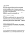
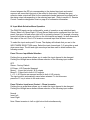
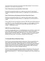
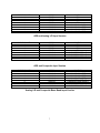
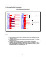
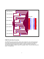
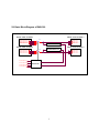
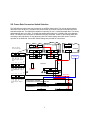
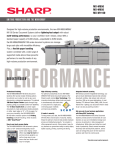
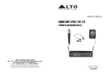
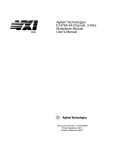
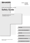
Broadcast Devices, Inc.
DAB-300 Digital Audio Broadcast
*Digital/Analog Audio Switcher DA
Operations Quick Start Guide
Broadcast Devices, Inc.
2066 E. Main Street
Cortlandt Manor, NY 10567
Tel. (914) 737-5032
Fax. (914) 736-6916
World Wide Web: www.Broadcast-Devices.com
Rev C 01/10
*Option Dependent
Table of Contents
I.
Basic Description
3
II.
DAB-300 Operational Description
3
III.
Remote Control Operation
3-4
IV.
Input Mode Selection Menu System
4-5
V.
Audio I/O Connector Diagrams
6-7
VI.
Remote Control Connector Diagrams
8-9
VII.
DAB-300-DAS Block Diagram
10
VIII.
Frame Rate Conversion Switch Selection
11
IX.
Warranty
12
2
I. Basic Description
The DAB-300 is a dual 4-channel audio switch intended for simultaneously
switching parallel program audio feeding analog and digital broadcast transmitters
where synchronous timing such as in IBOC operations is important to maintain. It
functions similar to a 4 position dual pole switch in that when audio to the analog
transmitter is switched, the output feeding the digital transmitter is switched to the
corresponding program source for the analog transmitter. Automatic silence detection
may be enabled to switch both analog and digital program feeds if either becomes silent
for a period which exceeds the user defined interval.
The DAB-300 can be ordered for four or eight inputs. The inputs can be AES3 digital
and/or analog L/R and composite base band depending on model.
II. DAB-300 Operational Description
The DAB-300 may be placed in the manual switching mode by pressing either the left or
right arrow key. The source selected will begin to flash. Select the desired input using
the up and down arrow keys. When the desired input channel is flashing press the
green enter key to accept the selection and switch to the selected input. If a channel is
not selected within 1 minute the DAB-300 will exit the manual switching mode
automatically. Note that the inputs will be selected in pairs. If Input 1 is selected to feed
the analog transmitter, Input 5 will be directed to the digital transmitter. The other inputs
(2/6, 3/7 and 4/8) are paired similarly.
III. REMOTE CONTROLLED OPERATION
The DAB-300 provides remote control to select between inputs and to enable/disable
remote operation. Open collector status outputs are provided to indicate the currently
selected input channel. These outputs are capable of sinking up to 100ma and are rated
at a maximum of 30v DC.
Remote Channel Selection:
The DAB-300 DAS provides 4 channel selection inputs and 4 channel status outputs on
the remote control DB-25 connector. Each output channel pair (1-4) is controlled via its
respective channel select pin (GPI 0-3) and provides a status output (GPO 0-3) which
reflects which of the 4 input pairs (1/5 through 4/8) is currently selected. A momentary
3
closure between the GPI pin corresponding to the desired input pair and control
common will cause that input pair to be routed to that output. Likewise the open
collector status outputs will float for the unselected channel pairs and be pulled low for
the status output corresponding to the selected input pair. Refer to section VI. Remote
Control Connector designation chart on page 9 for connection information.
IV. Input Mode Selection Menu Operation
The DAB-300 inputs can be configured for mode of operation on an individual basis.
Stereo, Mono Left, Mono Right, L+R and Stereo Swap can be configured from the front
panel. Use mono left and mono right to fill in a missing channel. For example; choosing
mono left will take a signal only input on the left channel and apply it to both channels at
the output of the unit. Use L+R to create a monaural input from a stereo source.
To select the input mode push F4 once. The display will indicate that you are in the
INPUT MODE SELECTION menu. Select the input channel pair (1-8) using the up and
down arrow keys. The left and right arrow keys are then used to select between the
following modes:
Press F4 once: Input Mode Selection
Pushing the up arrow/down allows you to select the input channel to be changed:
Pushing the left/right arrow buttons allows selection of the following input modes:
OFF
Stereo - Factory Default
LR Swap - L/R Channels Swapped
Mono L - L input fed to both L & R outputs
Mono R - R input fed to both L & R outputs
L + R - L & R inputs are summed and fed to both L & R outputs.
The input mode is automatically saved when selected. To exit this menu
press the F1 key to return to the main menu.
Press F4 twice: Input Invert Control – Phase Inversion
Pushing the up arrow/down allows you to select the input channel to be changed:
Pushing the left/right arrow buttons allows selection of the following input modes:
Normal
Invert Left
Invert Right
Note: Phase inversion is Left or right but not both simultaneously.
4
Input Invert Control modes are automatically saved when selected. To exit this menu
press the F1 key to return to the main menu.
Press F4 three times to enter Input Gain Control menu
Pushing the up arrow/down allows you to select the input channel to be changed:
Pushing the left/right arrow buttons allows you to adjust gain in one dB increments +/10 dB
Press F4 four times and the display will indicate Output Gain Control
Pushing the up arrow/down allows you to select the output channel to be changed:
Pushing the left/right arrow buttons allows you to adjust gain in one dB increments +/10 dB
Factory default for input and output gain controls is 0 dB. When factory default gains are
used AES3 I/O is unity. When AES3 inputs are output to an analog channel the analog
output will correspond to –10 dB below full scale AES3 input when AES3 input is
nominal – 10 dB below full scale.
DAB-300 Factory Default Recovery
As with any programmable device, it is possible that the user would like to quickly return
to the “factory default” settings. To return the DAB-300 to its factory configuration
remove AC power to the unit. While holding the red “X” key, restore AC power until the
display indicates “FACTORY DEFAULT”. The default condition is such that outputs 1
through 4 are fed by input 1 and outputs 5 through 8 are fed by input 5.
V. Automatic Silence Detection Setup
Push F3 once to enter the silence detection setup menu. Doing so presents the user
with a dialog which sets the silence detection interval. The factory default silence
detection time is 60 seconds. Values ranging from 10 to 600 seconds may be selected
using the up and down arrow keys. Broadcast Devices strongly suggests that silence
detection intervals of less than 60 seconds be tested carefully to verify that normal
program content does not cause undesirable switching.
Push F3 a second time to select the silence detection threshold level. This is the audio
level below which the DAB-300 considers the input to be silent (inactive). The factory
default silence threshold is “5”. This level may be changed using the up and down arrow
keys.
5
Push the F3 key a third time to enable / disable the auto-return function and to set the
auto-return time. The auto-return function will cause the DAB-300 to return to the
channel pair which was selected prior to a loss of audio detection and subsequent autoswitching. Using the up and down arrow keys intervals ranging from 1-10 minutes may
be selected or the auto-return function may be disabled.
A 4th press of the F3 key will move to the Audible Alarm Config menu. The audible
alarm will sound when a loss of audio has been detected if enabled. Use the up and
down arrow keys to enable or disable the audible alarm.
Pressing the F3 key a 5th time will move to the AUX RELAY CONFIG menu. Using the
up and down arrow keys the AUX RELAY may be set to either close and remain closed
or to issue a momentary 1 second closure upon loss of audio. Using the momentary
function can be useful in applications such as starting a CD player to be used as a
backup program audio source.
Press F1 to exit the silence detection setup dialogs.
VI. Audio I/O Connections
DAB-300 Audio Connections
DIGITAL AUDIO I/O
1
14
2
15
3
16
4
17
5
18
6
19
7
20
8
21
9
22
10
23
11
24
12
25
13
DB-25
ANALOG AUDIO - INPUT & OUTPUT PINOUTS ARE IDENTICAL
AESOUTP4
AESOUTN4
CH4 OUT
AESINP4
AESINN4
CH4 IN
AESOUTP3
AESOUTN3
CH3 OUT
AESINP3
AESINN3
CH3 IN
AESOUTP2
AESOUTN2
CH2 OUT
AESINP2
AESINN2
CH2 IN
AESOUTP1
AESOUTN1
CH1 OUT
AESINP1
AESINN1
CH1 IN
1
14
2
15
3
16
4
17
5
18
6
19
7
20
8
21
9
22
10
23
11
24
12
25
13
CH8P
CH8N
CH8 RIGHT
CH7P
CH7N
CH8 LEFT
CH6P
CH6N
CH 7 RIGHT
CH5P
CH5N
CH 7 LEFT
CH4P
CH4N
CH 6 RIGHT'
CH3P
CH3N
CH 6 LEFT
CH2P
CH2N
CH5 RIGHT
CH1P
CH1N
CH5 LEFT
DB-25
DAB-300 AUDIO INPUT MAPPING
MODEL DEPENDENT
6
INPUT CHANNEL
1
2
3
4
5
6
7
8
TYPE
DIGITAL
DIGITAL
DIGITAL
DIGITAL
ANALOG
ANALOG
ANALOG
ANALOG
LOCATION
AES 1
AES 2
AES 3
AES 4
ANALOG IN 1-2 (L/R)
ANALOG IN 3-4 (L/R)
ANALOG IN 5-6 (L/R)
ANALOG IN 7-8 (L/R)
AES and Analog L/R Input Version
INPUT CHANNEL
1
2
3
4
5
6
7
8
TYPE
DIGITAL
DIGITAL
DIGITAL
DIGITAL
ANALOG
ANALOG
ANALOG
ANALOG
LOCATION
AES 1
AES 2
AES 3
AES 4
COMPOSITE BASE BAND 1
COMPOSITE BASE BAND 2
COMPOSITE BASE BAND 3
COMPOSITE BASE BAND 4
AES and Composite Input Version
INPUT CHANNEL
1
2
3
4
5
6
7
8
TYPE
ANALOG
ANALOG
ANALOG
ANALOG
ANALOG
ANALOG
ANALOG
ANALOG
LOCATION
ANALOG IN 1-2 (L/R)
ANALOG IN 3-4 (L/R)
ANALOG IN 5-6 (L/R)
ANALOG IN 7-8 (L/R)
COMPOSITE BASE BAND 1
COMPOSITE BASE BAND 2
COMPOSITE BASE BAND 3
COMPOSITE BASE BAND 4
Analog L/R and Composite Base Band Input Version
7
VI. Remote Control Connections
DAB-300 Remote Connections
REMOTE P1
1
14
2
15
3
16
4
17
5
18
6
19
7
20
8
21
9
22
10
23
11
24
12
25
13
DB-25 FEMALE
INPUT COM
INPUT COM
INPUT COM
INPUT COM
INPUT COM
INPUT COM
INPUT COM
+12V
CHASSIS
SELECT-INPUT1/5
STATUS- 1/5 ACTIVE
SELECT-INPUT2/6
STATUS- 2/6 ACTIVE
SELECT-INPUT3/7
STATUS- 3/7 ACTIVE
SELECT-INPUT4/8
STATUS- 4/8 ACTIVE
COMP DECODE 1
COMP DECODE 2
COMP DECODE 3
COMP DECODE 4
REMOTE P2
1
14
2
15
3
16
4
17
5
18
6
19
7
20
8
21
9
22
10
23
11
24
12
25
13
K1-COM
K1-NC
K1-NO
K2-COM
K2-NC
K2-NO
FAULT DETECTED RELAYS
AUTO
AUTO-COM
MANUAL
MANUAL-COM
REMOTE ENABLE
REMOTE ENABLE COM
FAULT RESET
FAULT RESET COM
REMOTE INPUTS
CHASSIS
DB-25 FEMALE
Notes:
1. Status outputs are open collector Darlington transistors capable of sinking
100ma @ 30v DC.
2. Select and remote inputs are momentary closures with internal 4.7K pullup
resistors to 5v DC.
3. Any of the first four AES or analog L/R inputs can be substituted for
composite input by strapping the respective COMP DECODE pin to INPUT
COM as illustrated in the above figure. Then strapped, the normal 1-4 input
will be substituted for a composite input 1-4.
8
K1
AUDIO ALARM RELAY 1
+5V
CIT J1031C5VDC.15S
K2
AUDIO ALARM RELAY 2
+5V
CIT J1031C5VDC.15S
K3
AUDIO ALARM RELAY 3
+5V
CIT J1031C5VDC.15S
K4
AUDIO ALARM RELAY 4
AUDIO ALARM RELAY
K1
K2
K3
K4
K5
K6
5 K7
K8
+5V
CIT J1031C5VDC.15S
K5
+5V
AUDIO ALARM RELAY 6
AUDIO ALARM
CIT J1031C5VDC.15S
K6
+5V
1
14
2
15
3
16
4
17
5
18
6
19
7
20
8
21
9
22
10
23
11
24
12
25
13
1
14
2
15
3
16
4
17
5
18
6
19
7
20
8
21
9
22
10
23
11
24
12
25
13
CIT J1031C5VDC.15S
DB25 Female
DB25 Male (User Supplied)
K7
AUDIO ALARM RELAY 7
+5V
CIT J1031C5VDC.15S
K8
AUDIO ALARM RELAY 8
+5V
CIT J1031C5VDC.15S
DAB-300 Audio Alarm Connection
The DAB-300 provides audio failure alarm status contacts for each of the eight inputs.
Each relay is held closed when audio is present. If audio is removed for at least five
seconds the respective relay will de energize. If audio is restored for at least five
seconds the respective channel relay will re energize. Relay 1-8 provide audio status for
inputs 1-8 respectively
9
VII. Basic Block Diagram of DAB-300
DIGITAL AUDIO I/O BOARD 1
PGM AUDIO
PGM AUDIO
PGM AUDIO
PGM AUDIO
DIGITAL AUDIO I/O BOARD 1
S1A
INPUT 1
INPUT 2
INPUT 3
INPUT 4
SILENCE DETECT 1-4
DIGITAL AUDIO I/O BOARD 2
PGM AUDIO
PGM AUDIO
PGM AUDIO
PGM AUDIO
INPUT 5
INPUT 6
INPUT 7
INPUT 8
OUT 1
OUT 2
OUT 3
OUT 4
DIGITAL AUDIO I/O BOARD 2
S1B
SILENCE DETECT 5-8
DIGITAL
DIGITAL
DIGITAL
DIGITAL
GPIO-0 SELECT 1
GPIO-1 SELECT 2
DIGITAL
DIGITAL
DIGITAL
DIGITAL
DAS-300 CPU
GPIO-2 SELECT 3
GPIO-3 SELECT 4
1
OUT 5
OUT 6
OUT 7
OUT 8
VIII. Frame Rate Conversion Switch Selection
The DAB-300 has active frame rate conversion on all AES3 digital inputs. The unit can accept sample
rates from 8 KHz to 96 KHz. The frame rate converter then up or down converts the sample rate to the
selected sample rate. The DAB-300 is capable of outputting 32, 44.1 or 48 KHz sample rates. The factory
default sample rate is 44.1 KHz. To change the sample rate to either 32 or 48 KHz refer to the diagram
below. The sample rate converters are located on the AES I/O board. Locate S1 and change SR0, SR1
according to the chart below. Do not adjust any other DIP switch setting as this will result in incorrect
operation of the DAB-300. Correct DIP switch settings are provided for convenience.
4
3
2
J1
J2
J2
J4
J2
J4
J1
J3
J1
J3
A1
5
J5
1
A0
A1
A2
INT
M/S
TDM
SR0
SR1
32 KHz Output Sample
Rate
7
6
5
4
3
2
IDC DB-25
S1
1
DSP BOARD
P5
S1
ON
A0
A1
A2
INT
M/S
TDM
SR0
SR1
44.1 KHz Output Sample
Rate
P8
S1: 1-4-5 = ON
Hardw ire d
P7
P3
S1
8
7
6
5
4
3
2
1
REV B FP ONLY
ON
A0
A1
A2
INT
M/S
TDM
SR0
SR1
48 KHz Output Sample
Rate
GPIO BOARD
J2
ON
8
A2
6
J2
A0
7
INT
AES AUDIO I/O BOARD
S1
8
ON
S1
AES I/O Board
Switch Settings
ANALOG AUDIO OUT BOARD
S1
All On
S1
On
J4
FRONT PANEL REV C AND HIGHER
AS VIEWED FROM TOP W/ FRONT PANEL HINGED DOWN
P5
P1
FRONT PANEL REV B
AS VIEWED FROM TOP W/ FRONT PANEL HINGED DOWN
P6
P5
1
P1
IX. Warranty
Broadcast Devices, Inc. products are warranted against failure due to faulty materials
or workmanship for a period of one year from the date of shipment to the ultimate user.
The warranty covers repair or replacement of defective parts at the factory, provided the
unit has been returned prepaid by the user. All shipments to the factory shall have
affixed to the outside of the container a return authorization number obtained from the
factory. The above warranty is void if the unit has been modified by the user outside of
any recommendations from the factory or if the unit has been abused or operated
outside of its electrical or environmental specifications. If customer conducted field tests
suggest that the unit may be faulty, whether or not the unit is in warranty, a full report of
the difficulty should be sent to Broadcast Devices, Inc. factory at Cortlandt Manor, New
York. The office may suggest further tests or authorize return for factory evaluation.
Units sent to the factory should be well packed and shipped to Broadcast Devices,
Inc. 2066 E. Main Street, Cortlandt Manor, NY 10567. Remember to affix the R.A.
number to the outside of the carton. Any packages received without such R.A. number
will be refused. Note: freight collect shipments will also be refused. When the unit has
been received, inspected and tested, the customer will receive a report of the findings
along with a quotation for recommended repairs, which are found falling outside of the
standard warranty. Units returned for in-warranty repairs, which are found not to be
defective will be subject to an evaluation and handling charge. In-warranty units will be
repaired at no charge and returned via prepaid freight.
Out-of-warranty units needing repair require a purchase order and will be invoiced for
parts, labor, and shipping charges.
When ordering replacement part, always specify A) Part Description, and Quantity; B)
Date of Purchase, Where Purchased; C) Any Special Shipping Instructions. Always
specify a street address, as shipping companies cannot deliver to a postal box.
Broadcast Devices, Inc. is not responsible for any other manufacturer’s warranty on
original equipment. Nor are we responsible for any failure, damage, or loss of property
that may occur due to the installation or operation of our equipment outside of
recommended specifications.
1
Broadcast Devices, Inc. reserves the right to change materials, specifications, and
features from time to time.
www.broadcast-devices.com
Broadcast Devices, Inc.
2066 E. Main Street Cortlandt Manor, NY 10567 Email:
[email protected] (914) 737-5032 Tel.
1
(914) 736-6916 Fax.