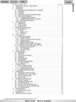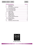
1
CONTENTS
PRINT
<
>
CONTENTS (ENGLISH)
CONTENTS
1
UNPACKING
2
SERIAL NUMBER
3
FEATURES
4
WARNINGS
5
CAUTION
6
USER RESPONSIBILITY
Loudspeaker Damage
Shock Hazard
Radio Interference
7
INTRODUCTION
Input Level Attenuators
On/Off Switch / Front Panel Indicators
Plug In Card / Module
Front Panel
Function Switches
Rear Panel
Input Sockets
Output Sockets / Ground Lift Switch
Mains Voltage / Selection
8
PROTECTION SYSTEMS
Fuse Information
9
INSTALLATION
Mounting
Cooling
10 OPERATING VOLTAGE
Mains Connections
Grounding
11 POWER CONSUMPTION
12 INPUT CONNECTIONS
Balanced / Unbalanced
13 OUTPUT CONNECTIONS
14 CONNECTING LOUDSPEAKERS
15 OPERATING MODES
Stereo / Tandem (Dual mono)
Input Mono Sum
Bridged Mono
16 OPERATING PRECAUTIONS
Powering Up / Input Attenuators / Gain Switch / Indicators
17 PROTECTION FEATURES
Output Power Limiter / Amplifier Thermal Protection
DC Protection
Short Circuit / Over Current Protection
High Frequency Protection
POWER SUPPLY THERMAL PROTECTION
18 MAINTENANCE
Replacement Fuses
19 WARRANTY
20 TECHNICAL SPECIFICATION
E1300 Plug In Processing Modules
GUIDES
Page No
1
2
2
2
3
4
4
4
4
4
5
5
5
6
6
6
7
7
7
8
9
9
10
10
10
11
11
11
12
13
14
15
15
16
16
16
16
17
17
18
18
19
19
19
19
20
20
21
22
23
All material © 2007. Martin Audio Ltd. Subject to change without notice.
Martin Audio – E1300 Amplifier
<
PRINT
>
GUIDES
This equipment conforms to the requirements of the
EMC Directive 89/336/EEC, amended by 92/31/EEC
and 93/68/EEC and the requirements of the Low
Voltage Directive 73/23/EEC, amended by 93/68/EEC
Standards Applied
1
EMC Emission
Immunity
Electrical Safety
EN55103 - 1: 1996
EN55103 - 2: 1996
EN60065: 1998
UNPACKING
Every Martin Audio E1300 Amplifier is built to the highest standards and is
thoroughly tested and inspected before it leaves the factory. After
unpacking the amplifier, examine it carefully for any signs of transit
damage, and inform your dealer if any such damage is found. It is
suggested that you retain the original packaging so that the unit can be
returned at a future date if necessary.
Please note that Martin Audio and its distributors cannot accept
responsibility for damage to any returned product through the use of noneapproved packaging.
2
SERIAL NUMBER
Every E1300 amplifier has an individual serial number marked on the rear
of the unit. Please make a separate copy of this number and quote it on
any correspondence referring to the amplifier. This serial number provides
us with technical data exclusive to each amplifier.
3
FEATURES
1. Plug in front panel module facility eliminating the need for external
controllers
2. High frequency switching power supply, with on board intelligent control
3. Custom heat exchanger with massive surface area and turbulent flow
4. Intelligent inter-dependent logic controlled power supply and audio
protection circuits
5. Dual fan 4-stage thermal control, ensuring the amplifier will provide
maximum performance under any condition
6. Dual die output devices providing high current and reactive load
capabilities
7. Automatic protection against severe amplifier clipping
2
All material © 2007. Martin Audio Ltd. Subject to change without notice.
Martin Audio – E1300 Amplifier
ENGLISH
CONTENTS
<
PRINT
>
GUIDES
8. Bridgeable output stage
9. Switchable high pass filters, frequency selectable
10. Balanced XLR inputs with link outs, and dedicated sub bass outputs
(when using plug in module)
11. Selectable input sensitivities and input mono sum facility
12. Speakon output sockets for Channel A, Channel B, and Bridge
4
WARNINGS
Do not use this amplifier if the mains cable is damaged.
Always operate this amplifier with the chassis ground wire connected
to the electrical safety earth.
Do not parallel or series connect an amplifier output with any other
amplifier output.
Do not connect the amplifier output to any other voltage source, such
as a battery, mains source or power supply, regardless of whether the
amplifier is turned "ON" or "OFF".
Do not run the output of any amplifier back into another channels
input.
Do not block the air intake or exhaust ports.
Do not operate the amplifier on or near any source of heat.
Do not stand water or any other liquid on or near the amplifier.
Do not spill or splash water, or any other liquid into or onto the
amplifier.
Do not operate the amplifier if liquid ingress is suspected.
Do not remove top cover. Removal of the cover will expose hazardous
lethal voltages and currents and may invalidate warranty.
Keep this manual for future reference.
3
All material © 2007. Martin Audio Ltd. Subject to change without notice.
Martin Audio – E1300 Amplifier
ENGLISH
CONTENTS
5
PRINT
<
>
GUIDES
CAUTION
There are no user serviceable parts inside this amplifier. Removal of
the cover by unauthorised personnel may invalidate warranty and will
result in exposure to lethal high voltage and current. In the unlikely
event of a fault developing within the E1300 refer servicing to qualified
personnel only.
6
USER RESPONSIBILITY
Loudspeaker Damage
Many loudspeakers can be easily damaged or destroyed by overpowering,
especially with the high power available from a bridged amplifier. Always
check the loudspeaker continuous and peak power capability. Even if the
gain is reduced by using the amplifier front panel attenuators, it is still
possible to reach full power output, if the input signal level is high enough.
Shock Hazard
Power amplifiers are capable of producing hazardous output voltages. To
avoid electrical shock, do not touch any exposed loudspeaker wiring when
the amplifier is operational. See page 15 for correct connection of
loudspeakers.
Radio Interference
A sample of this product has been tested and complies with the limits for
the European Electro Magnetic Compatibility (EMC) directive. These limits
are designed to provide reasonable protection against harmful interference
from electrical equipment. This amplifier uses radio frequency energy and if
not used or installed in accordance with these operating instructions, may
cause interference to other equipment. Compliance with the (EMC)
directive does not automatically guarantee non-disturbance of susceptible
equipment in close proximity to this amplifier.
If the amplifier is suspected of causing interference, this can be easily checked
by powering the unit "ON" and "OFF", and observing the disturbance. The
user can correct the interference by one or more of the following steps:
1. Increase the distance between the equipment.
2. Connect the power cable to a socket on a different circuit from that to
which the affected unit is connected.
3. If a radio receiver is affected (normally only AM receivers are affected);
Re-orientate the antenna.
4. Check if the affected equipment complies with the EMC limits for
immunity, (CE-labelled). If not, address the problem with the
manufacturer or supplier. All electrical products sold in the EC must be
approved for immunity against electromagnetic fields, high voltage
flashes and radio interference.
4
All material © 2007. Martin Audio Ltd. Subject to change without notice.
Martin Audio – E1300 Amplifier
ENGLISH
CONTENTS
7
PRINT
<
>
GUIDES
INTRODUCTION
Thank you for purchasing a Martin Audio power amplifier. This manual
contains important information on operating your amplifier correctly and
safely. Please take some time to read this manual and familiarise yourself
with the advanced features of this amplifier.
1. Carry Protection Handle. Both handles can be used to carry the
amplifier; they also act as a protection for the front panel and the controls.
In fixed installations or where rack front covers are too shallow, they may
be removed by unscrewing the retaining bolts behind the front panel.
2. Input Level Attenuators. These controls are used to set the signal input
levels to Channel A and Channel B. When the controls are in the fully
clockwise position the maximum gain of the amplifier can be utilised.
3. On / Off Switch. The power switch for the amplifier is located to the right
hand side of the front panel. The amplifier is "ON" when the switch is
Down. A red LED will illuminate to show the presence of mains power.
Note: The power switch must remain accessible when the amplifier is
installed. The power switch must be turned "OFF" then back "ON" to
restart the amplifier after a protection shut down has occurred. (See
page 18)
4. Signal Present Indicators. Adjacent to each level control are two green
LED’s, which indicate input level to the amplifier.
5. -3dB Level Indicators. Adjacent to each level control are two amber
LED’s, which indicate when approx half of the amplifier’s power is being
delivered.
6. Max Level Indicators. These red LED’s illuminate when the full power of
each amplifier channel is being delivered.
7. Power ON Indicator. This illuminates when power is connected to the
amplifier and the front panel switch 3 is in the "ON" position.
8. Card Enable Indicator. This illuminates when a processing module is
connected.
5
All material © 2007. Martin Audio Ltd. Subject to change without notice.
Martin Audio – E1300 Amplifier
ENGLISH
CONTENTS
PRINT
<
>
GUIDES
9. Bridged Indicator. This illuminates when bridge mode is selected
(function switch SW 5 is pushed IN).
10. Thermal Indicator. This indicates the thermal status of the amplifier.
See page 19 for a full description.
Plug In Card / Modules. The E1300 has the facility to accept a Martin
Audio processing module. When fitted it replaces the removable panel on
the front of the amplifier. It is connected to the main motherboard by a
flexible ribbon cable.
Front Panel
Function switches. To access the E1300 function switches, remove the
plug in module / front panel. There are 5 push button switches mounted on
the main motherboard.
SW 1 selects the high pass cut off frequency. Standard frequencies 15Hz
and 30Hz. (30Hz when IN).
SW 2 is high pass filter in / out. (High Pass in when IN).
SW 3 selects the amplifier gain 36dB (0.775v input sensitivity) or 32dB
(1.23V input sensitivity). (32dB when IN).
SW 4 mono sums the inputs. (When IN).
SW 5 is the Output Bridge select. When in bridge mode Channel A input
should be used with Channel A gain control. (Bridged when IN).
When all switches are out, the amplifier is configured unbridged, stereo, the
gain is 36db (0.775v input sensitivity). The high pass filter is out and the
turnover frequency is 15Hz.
6
All material © 2007. Martin Audio Ltd. Subject to change without notice.
Martin Audio – E1300 Amplifier
ENGLISH
CONTENTS
PRINT
<
>
GUIDES
Rear Panel
1. Fuse holder. The E1300 is fitted with a bayonet style 1/4 turn fuse holder.
See pages 9 & 20 for fuse details and type.
2. Mains Power Connection. The E1300 is supplied with a 1.5M, 3 core
captive cable. (See page 11).
3. Air Inlets. The E1300 uses forced air cooling for efficient operation.
These inlets take in air which is exhausted from the front of the amplifier.
4, 5 and 6. Output Sockets. The amplifier is provided with 3 NL4
SPEAKON output sockets. Connection to the SPEAKON sockets can only
be made with a SPEAKON plug. The output of Channel A, Channel B, and
bridge appear on pins +1 and -1; Pins +2 and -2 are open circuit.
Note: It is important that the correct polarity is observed when
connecting your loudspeaker system. The positive (in phase) output
must always be connected to pin +1, the negative (none phase) output
should be connected to pin -1.
7. Ground Lift Switch. This switch isolates the electrical earth from the
signal 0V (signal ground). When in the lift position earth currents are
prevented from circulating, by inserting an R.C. network between 0V and
Earth.
8. and 9. Input Sockets. 3 pin female XLR connectors are provided for
signal input.
7
All material © 2007. Martin Audio Ltd. Subject to change without notice.
Martin Audio – E1300 Amplifier
ENGLISH
CONTENTS
PRINT
<
>
GUIDES
10. Line Level Output Socket. When a processing module is fitted, left
and right sub bass signals can be routed to this output. See module
operating instructions for a full description.
11. and 12 Input Link Sockets. 3 pin male XLR connectors are provided
which are connected in parallel with the input sockets. These can be used
for "daisy chaining" the signal to other amplifiers.
Mains Voltage Selection. The E1300 is dual voltage selectable; it is
normally supplied pre selected for 220/240 Volt AC operation only. For use
on 110/115 Volts AC, internal modifications must be made.
Warning: This modification should only be carried out by an
experienced service technician.
Contact Martin Audio Ltd or an appointed distributor for details.
8
All material © 2007. Martin Audio Ltd. Subject to change without notice.
Martin Audio – E1300 Amplifier
ENGLISH
CONTENTS
8
PRINT
<
>
GUIDES
PROTECTION SYSTEMS
The E1300 is provided with multiple protection circuits, these include
current and dissipation limiting in the output stage, plus short circuit and
high frequency protection. The power supply also has its own independent,
start-up and shutdown hierarchy plus short circuit and over current
protection.
Fuse Information
1. External mains fuse ceramic:
10 Amp Type T (H) (220-240V)
16 Amp Type T (H) (100-120V)
It is essential that if the fuse needs to be replaced for any reason it is only
replaced with the correct type. The correct fuse allows the E1300 to deliver
full power without danger. If a fuse of lower current rating than specified is
used, or with different fusing characteristics, it will blow prematurely, whilst
a fuse of a higher rating than recommended, is unsafe and dangerous, and
could cause fire, or catastrophic failure in the event of a fault developing
within the amplifier. For details of fuse type, part numbers, and suppliers
(see page 20).
2. Internal fuse 10 Amp Type T (H)
In the event of this DC fuse needing to be replaced, it must be replaced
with a fuse of the same type and current rating. Warning: This should
only be carried out by an experienced service technician. See fuse
specification page 9 & 20.
CAUTION!
DANGEROUS VOLTAGES MAY EXIST IN THIS AMPLIFIER EVEN AFTER
SWITCHING OFF! REFER SERVICING TO QUALIFIED PERSONNEL
ONLY
WARNING!
WAIT AT LEAST FIVE MINUTES BEFORE REPLACING FUSE
9
All material © 2007. Martin Audio Ltd. Subject to change without notice.
Martin Audio – E1300 Amplifier
ENGLISH
CONTENTS
9
PRINT
<
>
GUIDES
INSTALLATION
Mounting
The amplifier is two-rack unit's high (2U) and will mount in a standard EIA
19" rack. Amplifiers may be stacked directly on top of each other; there is
no need for spacing between units. If it is the intention to fill a rack with
amplifiers, we recommend racking be started from the bottom of the rack. It
is also recommended that rear supports be used for amplifiers, especially if
used as part of a portable system.
Cooling
Your amplifier uses forced air-cooling to maintain an even operating
temperature. All Martin Audio E series amplifiers have rear to front cooling.
Never try to reverse the airflow, as the amplifier needs a pressure chamber
between the fans and the heatsink and this only operates in one direction
of the airflow. Warning: never rack different brands of amplifiers
together with opposing airflow characteristics.
Make sure that there is adequate air supply at the rear of the amplifier and
that the front of the amplifier has sufficient space at the front to allow the
exhaust to escape. If the amplifier is rack mounted, do not use covers or
doors on the front and rear of the rack. For fixed installations with a central
cooling system, and dedicated rack room, it may be necessary to calculate
the maximum heat emission. See page 13.
10
All material © 2007. Martin Audio Ltd. Subject to change without notice.
Martin Audio – E1300 Amplifier
ENGLISH
CONTENTS
10
PRINT
<
>
GUIDES
OPERATING VOLTAGE
WARNING!
A label above the mains power cable on the rear of the amplifier
indicates the selected AC mains operating voltage.
Connect the power cable only to the AC source referred to on the
label. The warranty will not cover damage caused by connecting to the
wrong type of AC mains.
For converting a 230 volt amplifier to 115 volts or vice versa, contact
Martin Audio Ltd or an approved Martin Audio dealer.
Martin Audio E series amplifiers use primary switching, i.e. the mains is
rectified directly before the transformer, which means that the power supply
is insensitive to the mains frequency.
Mains Connections
The amplifier is supplied with 1.5M of un-terminated 3-core cable and
should be connected as below to a suitable plug or outlet.
BROWN
BLUE
GREEN/YELLOW
-
LIVE (POSITIVE +)
NEUTRAL (NEGATIVE -)
EARTH (CHASSIS)
Once connected to a suitable AC supply, the amplifier can be started with
the power switch. When you power up the amplifier it takes a few seconds
to self-check. (This is known as the "soft start" sequence). The fans will
start and the red power "ON" LED and red "max" power LED’s will
illuminate to show the amplifier is operational. If everything is ok the “max”
power LED’s will extinguish and the power LED will remain "ON".
Grounding
The E1300 is equipped with a ground lift switch at the rear of the amplifier.
Depending on the system wiring configuration, it may be necessary to
'LIFT' the signal ground. When the signal ground lift switch is operated it
interposes an RC network between chassis ground and signal 0V breaking
any ground loops that may be causing hum.
For compliance with the EMC directive (conducted emissions), the E1300 is
provided with an AC mains filter. This requires the mains earth to be
connected to ground at all times.
RISK OF SHOCK!
For safety reasons never operate the amplifier with the mains
earth disconnected.
11
All material © 2007. Martin Audio Ltd. Subject to change without notice.
Martin Audio – E1300 Amplifier
ENGLISH
CONTENTS
11
PRINT
<
>
GUIDES
POWER CONSUMPTION
There are three ways to define the power/current consumption of the
amplifier.
First, the peak current draw at full sine wave power output. Under this
condition the amplifier could thermally limit or blow the mains fuse, and is
an unrealistic ‘normal’ use condition. To design a mains distribution system
based on the current draw at full power would result in an over specified
system. No music programme material requires the full steady state
continuous power of an amplifier; this operating condition is only valid for
amplifier bench testing.
Second, the maximum expected average current under worst case
conditions, which corresponds to 1/3 of full power according to the FTC
standard. At this level the program material will be in a state of constant clip
and is the highest power level that can be obtained without completely
obliterating the program content.
Lastly, the "normal operating power", as defined by EN60065 as a
measurement level for approval and testing to this standard. The normal
operating power is measured using pink noise, with an average output
power equal to 1/8 of full power. The 1/8 power is the maximum volume music
can be replayed without continuous amplifier clipping, corresponding to a
headroom of 9dB's, which is very low for normal program material; 12 to
15dB’s is a more realistic figure.
If operating both channels of the amplifier into a sustained 2 ohm load,
protection circuits within the amplifier could be triggered due to thermal or
over current protection, and the amplifier will shut down. To reset the
amplifier, it must be switched "OFF" then back "ON".
12
All material © 2007. Martin Audio Ltd. Subject to change without notice.
Martin Audio – E1300 Amplifier
ENGLISH
CONTENTS
>
GUIDES
Power Table
E1300 OUTPUT POWER
E1300 MAINS INPUT POWER
1/3
POWER
1/8
POWER
IDLE
8 Ohm
2X
400
680
400
117
4 Ohm
2X
720
1220
700
117
2 Ohm
2X
1000
1880
1200
117
1/3 Power level = Average power with music as programme source. The amplifier driven to clip level
1/8 Power level = Normal operating power with music as programme source, 9dB headroom
Heat Power Table
E1300 HEAT POWER
1/3
POWER
1/8
POWER
1/3
POWER
Watts
1/8
POWER
1/3
POWER
Kcal/hour
1/8
POWER
BTU/hour
8 Ohm
370
300
93
78
1262
1058
4 Ohm
660
530
166
133
2252
1800
2 Ohm
1280
900
320
230
4354
3084
1/3 Power level = Average power with music as programme source. The amplifier driven to clip level
1/8 Power level = Normal operating power with music as programme source, 9dB headroom
12
INPUT CONNECTIONS
Both Channel A and Channel B inputs are electronically balanced on 3 pin
XLR type connectors, and wired pin 2 hot (+), pin 3 cold (-), and pin 1 Earth
or SIG 0V
13
All material © 2007. Martin Audio Ltd. Subject to change without notice.
Martin Audio – E1300 Amplifier
ENGLISH
<
PRINT
CONTENTS
PRINT
<
>
GUIDES
The input impedance is sufficiently high to allow daisy chaining or multiple
parallel input connections using the input 'Link' XLR.
Balanced line (source and input):
Unbalanced source with balanced input:
To minimize hum in the audio, use balanced connections whenever
possible.
14
All material © 2007. Martin Audio Ltd. Subject to change without notice.
Martin Audio – E1300 Amplifier
ENGLISH
CONTENTS
13
<
>
GUIDES
OUTPUT CONNECTIONS
When a Martin Audio processing module is fitted it can be configured to
output line level sub bass signals which may be fed to other amplifiers. The
balanced signal appears on the 5 pin XLR connector on the rear of the
amplifier.
Pin
Pin
Pin
Pin
Pin
1
2
3
4
5
SCREEN
CH,A
+
CH,A
–
CH,B
+
CH,B
–
The outputs of the module are not auto compensating, therefore when
driving an unbalanced input use only the + output and screen.
14
CONNECTING LOUDSPEAKERS
Loudspeaker connections are made via the three Neutrik NL4 Speakon
connectors 4, 5, and 6. These connectors meet the EC safety
requirements. They are wired as follows:
Pin
Pin
Pin
Pin
-1
+1
-2
+2
Speaker negative
Speaker positive
No connection
No connection
Never connect either output terminal to ground or to some other
output or input terminal
For normal two-channel operation, connect each loudspeaker load across
the outputs positive and ground terminals. Pay attention to loudspeaker
polarity; loudspeakers connected out of polarity can degrade sound quality.
15
All material © 2007. Martin Audio Ltd. Subject to change without notice.
Martin Audio – E1300 Amplifier
ENGLISH
PRINT
CONTENTS
PRINT
<
>
GUIDES
Keep the loudspeaker cables as short as possible and use good quality
stranded cable. Do not use shielded wire, such as microphone or guitar
cable. Remember that the loudspeaker cable robs the power of the
amplifier in two ways; it increases the load impedance and also introduces
resistive power losses.
15
OPERATING MODES
Stereo
For stereo dual channel operation ensure switch S4 (located behind the
plug in card panel on the front of the amplifier) is in the "OUT" position. In
this mode both channels are split and operate independently of each other,
with their level attenuators controlling their respective outputs. Never
connect either output terminal to ground or in parallel.
Tandem (Dual Mono)
For tandem (dual channel-single input) operation connect the link out of
one channel into the input of the other channel using an XLR to XLR cable.
Input Mono Sum
To mono sum input A and B together push "IN" switch S4 (located behind
the plug in module/panel on the front of the amplifier). A level drop of 6dB’s
will occur if only one input is used in this mode of operation. The output
connection is the same as in stereo mode.
Bridged Mono
To bridge the amplifier, depress switch S5 (located behind the removable
panel/module on the front of the amplifier) both channels are then fed by
input 'A'. The output in bridge mode appears on the dedicated 'Bridge out
Speakon'. Only Channel A level attenuator and the LED's associated with
Channel A are operational in bridge mode. If SW4 is depressed this will
sum together input A and B which will then be fed to the bridged output
stage.
Pin -1 Speaker negative
Pin +1 Speaker positive
NB. The recommended minimum nominal impedance for bridged mono is 4
Ohms (equivalent to driving both channels at 2 Ohms) Driving bridged
loads of 4 Ohms or lower with the “max” LED’s permanently "ON" may
trigger protection circuits within the amplifier due to current and thermal
demands. If an over current shut down occurs the power supply will shut
down. To restart the amplifier the power switch must be turned "OFF" then
back "ON". The input level to the amplifier must also be reduced or the
power supply will shut down again. (See page 18 Protection Features).
16
All material © 2007. Martin Audio Ltd. Subject to change without notice.
Martin Audio – E1300 Amplifier
ENGLISH
CONTENTS
16
PRINT
<
>
GUIDES
OPERATING PRECAUTIONS
Make sure the power switch is "OFF" before making any input or output
connections, installing a plug in module or operating any switches behind
the removable panel / plug in module.
Make sure that the AC mains are correct and that it is the same as that
printed on the back of the amplifier. See pages 11 & 12 regarding operating
voltage and power consumption.
It is always a good idea to turn down the gain controls during power up as
this prevents loudspeaker damage, especially if there is a high level signal
present at the input.
Powering Up
When the amplifier is first switched on the power "ON" and "max" LED’s
illuminates, it then takes a couple of seconds to self-check. If everything is
OK the "max" LED’s will extinguish and the power LED will stay "ON". This
is known as the "soft start" or "slow start" sequence, the fans then start and
the power amplifier is operational.
Input Attenuators
The two input level attenuators on the front panel adjust the signal level to
the respective amplifier channels. In bridged mode, only Channel A level
control is used.
Gain Switch
The gain switch (SW3) is located behind the plug in panel / module on the
front of the amplifier, when in the "OUT" position the gain of the amplifier is
36dB (input sensitivity 0.775Vrms), when in the "IN" position the gain of the
amplifier is 32 dB (input sensitivity 1.23Vrms).
When in bridge mode the amplifier sensitivity will remain the same in each
position of SW3, but the effective output gain will increase by 6dB’s in each
case, from 36dB to 42dB and from 32dB to 38dB. Most professional mixing
consoles operate at a nominal level of +4dBu. Therefore use the 32dB
position (SW3 switch IN). On MI or semi professional equipment that
operates at a nominal 0dBu level use the 36dB-gain setting (SW3 switch
OUT).
Indicators
The two bottom green LED's act as signal present indicators and operate
when the output signal is greater than -30dB's.
The yellow -3dB LED's indicate when approximately half of the power
capacity of the amplifier is being utilised.
The red "max" LED's indicate when the full capacity of the amplifier is being
used. Protection circuits within the amplifier allow the maximum output of
17
All material © 2007. Martin Audio Ltd. Subject to change without notice.
Martin Audio – E1300 Amplifier
ENGLISH
CONTENTS
PRINT
<
>
GUIDES
the amplifier to be used without severe hard clipping.
The "card enable" LED indicates when a dedicated processing module is
fitted in the amplifier.
The remaining red "thermal" LED indicates the temperature status of the
amplifier. The E1300 is fitted with a sophisticated thermal management
system. Under normal operation the thermal LED will be "OFF", if more
power is demanded from the amplifier, or airflow to the amplifier is
restricted the LED will start to flash to indicate an elevation in operating
temperature. If no action is taken at this point the third status level will be
reached, the thermal and limit LED’s will be "ON", and the amplifier will
protect itself by reducing the power to the load. When the amplifier has
cooled sufficiently the power will ramp back up to the previous level. If the
amplifier does not cool enough or the fans fail completely, the amplifier will
lock in a reduced power state until the problem is cleared.
17
PROTECTION FEATURES
Every Martin Audio E series amplifier has many advanced protection
features that will protect both the amplifier and the loudspeakers connected
to it, should a fault condition arise. Under normal use these features are
inaudible.
Output Power Limiter
An output limiter is included to avoid severe amplifier clipping. When an
amplifier is severely overdriven, its output waveform is clipped (its peaks
are squared off) - reducing the crest factor. In extreme cases, the waveform
can approach that of a square wave. An amplifier is capable of producing
far more power under these conditions than its normal undistorted rated
power output. If the distortion exceeds 1% THD for any reason the limiter
reduces the input signal proportionally. Note that, if the input signal is
clipped before it reaches the amplifier, the clip limiter will not be
activated and severe damage to the loudspeakers could occur.
Amplifier Thermal Protection
All high power amplifiers produce considerable heat as a product of power
output. The E1300 is equipped with a very efficient heat exchanger and an
automatic logic controlled thermal management system.
When the amplifier is switched on the dual fans will start up and remain at
a low idling speed. As the amplifier provides more power the fans may
switch to the second cooling level. Under sustained demand for high power
or when there is insufficient cooling, the third level of fan speed is reached
and the red “thermal” LED on the front panel will begin to flash.
If no action is taken to either reduce the power demand or increase the
airflow through the amplifier, it will automatically protect itself, by reducing
the power to the loudspeaker. The status of the “thermal” and “max” LED’s
will change to permanently "ON" and the green and amber signal LED’s will
extinguish.
18
All material © 2007. Martin Audio Ltd. Subject to change without notice.
Martin Audio – E1300 Amplifier
ENGLISH
CONTENTS
PRINT
<
>
GUIDES
When the amplifier has cooled back down to its normal operating
temperature the red “max” LED’s and “thermal” LED’s will extinguish. The
green and amber signal LED’s will become operational, and power to the
loudspeakers will ramp up to the previous set level.
DC Protection
If more than ±5 volts appears on the amplifier outputs the power supply will
shut down. Switch "OFF" the amplifier and check that the source of DC is
not external to the amplifier i.e. controller sense lines etc. If the fault has
been cleared, switch "ON" the amplifier and it should power up as normal.
If the amplifier shuts down again the DC voltage has either not been
cleared or the amplifier is faulty and will not power up again until it is
repaired. The amplifier has to be re-set by turning the amplifier "OFF" then
back "ON".
Short Circuit / Over Current Protection
The power supply will shut down if a short circuit appears on the amplifier
outputs, or the amplifier tries to supply more current than it can provide.
The amplifier has to be reset by turning the amplifier "OFF" then back "ON".
If the short circuit or very low impedance load is still present at the outputs,
the power supply will again shut down instantaneously.
High Frequency Protection
If the amplifier detects out of band high frequency, high power output
signals, the power supply will shut down, protecting the amplifier and HF
drive units from burnout. The amplifier has to be re-set by turning the
amplifier "OFF" then back "ON", to initiate a power up sequence.
Power Supply Thermal Protection
In the unlikely event that both fans become blocked or fail, the amplifier will
continue to operate until the power supply reaches its maximum operating
temperature. At this point a thermal trip will activate to prevent permanent
damage to the power supply, and the power supply will shut down. The
amplifier has to cool down to its normal operating temperature before it can
be re-started. The amplifier has to be turned "OFF" then back "ON" again,
to initiate a power up sequence. The cause of the blockage must be
removed or the fans replaced. The amplifier will not power up until the
temperature has dropped to a safe level.
19
All material © 2007. Martin Audio Ltd. Subject to change without notice.
Martin Audio – E1300 Amplifier
ENGLISH
CONTENTS
18
PRINT
<
>
GUIDES
MAINTENANCE
Under normal use the amplifier should give years of trouble free service.
Periodically it may be necessary to clean the inside of the amplifier. (This
should only be done by qualified service personnel).
If you are using your amplifiers for heavy-duty use i.e. Concert touring or
industrial music, it is recommended that you have your amplifier serviced
every three years, purely as a preventative measure. We recommend you
do not use the amplifier in environments using "cracked oil" smoke
machines, as condensed oil inside the amplifier can cause serious damage.
Replacement Fuses
220V-240V
10 Amp type T (H) Martin Audio Part No. (FUSE T 10AMP) manufactured
by SIBA 70-065-65 series
Stocked worldwide by Farnell Electronic Components (Farnell Part No. 159232)
100-120V
16 Amp type T (H) Martin Audio Part No. (FUSE T 16AMP) manufactured
by SIBA 70-065-65 series
Stocked worldwide by Farnell Electronic Components (Farnell Part No. 159256)
20
All material © 2007. Martin Audio Ltd. Subject to change without notice.
Martin Audio – E1300 Amplifier
ENGLISH
CONTENTS
19
<
PRINT
>
GUIDES
WARRANTY
General
The E1300 Power amplifier is warranted to be free from defects in
components and factory workmanship under normal use and service, for a
period of one year from the date of original purchase. During the warranty
period, MARTIN AUDIO LTD or its nominated agents, will undertake to
repair or at its discretion, replace this product at no charge to its owner,
when failing to perform as specified, provided the unit is returned
undamaged, in its original packaging, shipping pre-paid, to the factory,
distributor or authorised service facility.
This warranty shall be null and void, if the product is subjected to:
1. Repair work or alteration by persons other than those authorised by
MARTIN AUDIO LTD or its agents.
2. Shipping accidents, act of God, war, civil insurrection, misuse, abuse
operation with incorrect AC voltage, operation with faulty associated
equipment, exposure to inclement weather conditions and normal wear
and tear. Units, on which the serial number has been removed or
defaced, will not be eligible for warranty service
3. MARTIN AUDIO LTD shall not be responsible for any incidental or
consequential damages, with respect to the products warranted.
MARTIN AUDIO LTD reserve the right to make changes or improvements in
design or manufacturing, without assuming any obligation to change or
improve products previously manufactured.
This warranty is exclusive and no other warranty is expressed or implied.
This warranty does not affect your statutory rights.
International
Please contact your supplier for this information, as rights and disclaimers
may vary from country to country.
Technical assistance and services
International
If your Martin Audio product needs repair, contact your Martin Audio dealer
or distributor, or contact Martin Audio by fax or email to obtain the location
of the nearest dealer or distributor.
Telephone: + 44 (0) 1494 535312
Fax: + 44 (0) 1494 438669
E-mail: [email protected]
www.martin-audio.com
21
All material © 2007. Martin Audio Ltd. Subject to change without notice.
Martin Audio – E1300 Amplifier
ENGLISH
CONTENTS
20
<
PRINT
>
GUIDES
E1300 TECHNICAL SPECIFICATION
INPUT IMPEDANCE
20K Ohms differential, 10K Ohms single ended
INPUT SENSITIVITY
Selectable 0.775mv (36dB gain) or 1.23V
(32dB gain)
FREQUENCY RESPONSE
17Hz - 46KHz + 0dB – 3dB
POWER BANDWIDTH
10Hz - 40KHz + 0dB – 0.5dB
POWER OUTPUT
400 Watts Cont Av into 8 Ohms
720 Watts Cont Av into 4 Ohms
1000 Watts Cont Av into 2 Ohms
1440 Watts Cont Av bridged into 8 Ohms
OUTPUTS
Impedance
DC offset
22mΩ
<2mV
SLEW RATE
70 Volts per micro second
(SIGNAL + NOISE) / NOISE
RATIO
>100dB 20Hz - 20KHz IEC, A weighted
DISTORTION
< 0.06% @ 1dB below full power
POWER REQUIREMENTS
Operating voltage
Minimum start-up voltage
Peak inrush current
230V Setting
180* – 250Vac
140Vac
11.8 Amps
Current draw 4Ω
Quiescent (No load)
0.9 Arms
1/8 Full power (Both channels) 4.8 Arms
1/3 Full power (Both channels) 7.2 Arms
Dual voltage operation 115V
(internal Links).
115V Setting
90* - 125Vac
70Vac
23 Amps
1.8 Arms
9.6 Arms
14 Arms
or 230V
*Note: The amplifier will operate down to the indicated mains voltage but with
reduced power output.
AMBIENT TEMPERATURE
Maximum ambient operating temperature +40°C
INDICATORS
Power On, Signal Level, Bridge, Thermal,
Card/Module Enable
INPUT CONNECTIONS
2 x XLR with 2 x XLR parallel links
Pin 2 Hot, Pin 3 Cold
22
All material © 2007. Martin Audio Ltd. Subject to change without notice.
Martin Audio – E1300 Amplifier
ENGLISH
CONTENTS
<
PRINT
>
GUIDES
SIGNAL
Pin 1 Ground lifted via 470R // 100nF.
Options for pin 1 open circuit, and pin 1
connected directly to electrical earth
INPUT CONNECTION
POWER
Captive 1.5M 3-core cable
OUTPUT CONNECTIONS
3 x Speakon connectors, 1 x 5 pin XLR
(stereo line level sub bass out) this is only
active when a processing module is fitted
(minimum load impedance 1K ohms)
DIMENSIONS
(incl. Handles)
(W) 482mm x (H) 88mm x (D) 384.5mm
(W) 19ins x (H) 3.5ins x (D) 15.1ins
WEIGHT
9.5Kg (20.9lbs)
E1300 PLUG IN PROCESSING MODULES
System specific Martin Audio plug in modules are available for use with the
E1300 to eliminate the use of separate stand-alone controllers*.
To fit the module, first switch "OFF" the amplifier and remove the power
connection to the amplifier.
Unscrew the two retaining bolts that hold the removable panel on to the
front of the amplifier.
Unplug the grey ribbon cable from its 'park' position SK2 on the
motherboard and plug it into the header on the module. If any changes are
required to the function switches they should be done now before the
module is fitted. It is recommended that the high pass filter is switched "IN"
and set for 30Hz when using the module (SW1 and SW2 both pushed IN).
Refit the module into the front of the amplifier ensuring the ribbon cable is
folded under and is not trapped or stretched.
Reinstate the power connection to the amplifier and switch "ON". The green
Card Enable LED on the front panel should now be illuminated. The
selected filtered and equalised signals will now appear on the outputs of the
amplifier, and on the rear 5 way line level out, sub bass connector.
* Refer to E1300 module user guide for detailed set up information.
23
All material © 2007. Martin Audio Ltd. Subject to change without notice.
Martin Audio – E1300 Amplifier
ENGLISH
CONTENTS
CONTENTS
PRINT
<
>
E1300
GUIDES
Amplifier
Please Click here to
return to main menu
Please Click here to
visit our website
The Martin Experience
Century Point, Halifax Road, Cressex Business Park, High Wycombe, Buckinghamshire HP12 3SL, England.
Telephone: +44 (0)1494 535312 Facsimile: +44 (0)1494 438669
Web: www.martin-audio.com E-mail: [email protected]
All material © 2007. Martin Audio Ltd. Subject to change without notice.
CONTENTS
PRINT
<
>
E1300
GUIDES
Amplifier
User’s Guide
ENGLISH
The Martin Experience
All material © 2007. Martin Audio Ltd. Subject to change without notice.