1
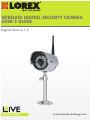
WIRELESS DIGITAL SECURITY CAMERA USER’S GUIDE English Version 1.0 LW2275 SERIES www.lorextechnology.com Thank you for purchasing this Lorex product. This manual refers to the following products: • LW2275 • LW2275PK2 To learn more about this product and to learn about our complete range of accessory products, please visit our website at: www.lorextechnology.com CAUTION RISK OF ELECTRIC SHOCK DO NOT OPEN CAUTION: TO REDUCE THE RICK OF ELECTRIC SHOCK DO NOT REMOVE COVER. NO USER SERVICABLE PARTS INSIDE. REFER SERVICING TO QUALIFIED SERVICE PERSONNEL. The lightning flash with arrowhead symbol, within an equilateral triangle, is intended to alert the user to the presence of uninsulated "dangerous voltage" within the products ' enclosure that may be of sufficient magnitude to constitute a risk of electric shock. The exclamation point within an equilateral triangle is intended to alert the user to the presence of important operating and maintenance (servicing) instructions in the literature accompanying the appliance. WARNING: TO PREVENT FIRE OR SHOCK HAZARD, DO NOT EXPOSE THIS UNIT TO RAIN OR MOISTURE. CAUTION: TO PREVENT ELECTRIC SHOCK, MATCH WIDE BLADE OF THE PLUG TO THE WIDE SLOT AND FULLY INSERT. Need Help? CONTACT US F I R S T DO NOT RETURN THIS PRODUCT TO THE STORE Please make sure to register your product at www.lorextechnology.com to receive product updates and information 3 Easy Ways to Contact Us: Online: Product Support is available 24/7 including product information, user manuals, quick start up guides and FAQ’s at www.lorextechnology.com/support To order accessories, visit www.lorextechnology.com By Email: Technical Support (for technical/installation issues) [email protected] Customer Care (for warranty and accessory sales) [email protected] Customer Feedback [email protected] By Phone: North America: Customer Service: 1-888-425-6739 (1-888-42-LOREX) Tech Support: 1-877-755-6739 (1-877-75-LOREX) Mexico: 1-800-514-6739 International: +800-425-6739-0 (Example: From the UK, dial 00 instead of +) Ma y 5 2011 - R11 VIEW YOUR WORLD™ VOIR VOTRE MONDEMD VER SUMUNDO™ ALWAYS AWARE™ TOUJOURS AU COURANTMD SIEMPRE CONSCIENTE™ Necesita Ayuda COMUNÍQUESE PRIMERO CON NOSOTROS SIMPLY AWARE™ SIMPLEMENT AU COURANTMD SIMPLEMENTE CONSCIENTE™ Vous Avez Besoin D’aide? CONTACTEZ-NOUS D’ABORD NO DEVUELVA ESTE PRODUCTO A LA TIENDA NE RETOURNEZ PAS CE PRODUIT AU MAGASIN Cerciórese de por favor colocar su producto en www. lorexcctv.com/registration para recibir actualizaciones y la información del producto Veuillez veiller à enregistrer votre produit à www.lorexcctv.com/registration pour recevoir des mises à jour et l’information de produit 3 3 maneras sencillas de comunicarse con nosotros: façons faciles de nous contacter: En línea: En ligne: apoyo al producto disponible 24/7 incluyendo información del producto, manuales para el usuario, guías de inicio rápido y preguntas más frecuentes en www.lorextechnology.com/support le support des produits est disponible 24 heures sur 24, 7 jours sur 7, y compris les informations sur les produits, les guides de l’utilisateur, les guides de démarrage rapide et les foires à questions Para colocar pedidos de accesorios, visite Pour commander des accessoires, visitez www.lorextechnology.com www.lorextechnology.com/support www.lorextechnology.com Por Correo Electrónico: Par Courriel: soporte técnico (para asuntos técnicos/la instalación) support technique (pour les questions techniques et ’installation) [email protected] servicio al cliente (respecto a la garantía y a la venta de accesorios) service à la clientèle (pour les questions de garantie et les ventes d’accessoires) Comentarios de cliente Commentaires des clients Por Teléfono: Par Téléphone: Norte América: Atención al cliente: 1-888-425-6739 (1-888-42-LOREX) Soporte técnico: 1-877-755-6739 (1-877-75-LOREX) L’Amérique du Nord: Service à la clientèle: 1-888-425-6739 (1-888-42-LOREX) Support technique: 1-877-755-6739 (1-877-75-LOREX) Mexico: 1-800-514-6739 Mexico: 1-800-514-6739 Internacional: +800-425-6739-0 International: +800-425-6739-0 (Ejemplo: Desde el Reino Unido, marque el 00 en lugar del +) (Exemple: À partir du Royaume-Uni, composez 00 au lieu de +) [email protected] O [email protected] [email protected] OU [email protected] [email protected] Ma y 5 2011 - R11 B E F O R E Y O U S TA R T THIS PRODUCT MAY REQUIRE PROFESSIONAL INSTALLATION LOREX IS COMMITTED TO FULFILLING YOUR SECURITY NEEDS • We have developed user friendly products and documentation. Please read the Quick Start Guide and User Manual before you install this product. • Consumer Guides and Video Tutorials are available on our web site at www.lorextechnology.com/support • If you require further installation assistance, please visit www.lorextechnology.com/installation or contact a professional installer. • Please refer to the “Need Help” insert for technical support and customer care information. • Please note that once the components of this product have been unsealed, you cannot return this product directly to the store without the original packaging. May 5 2011 - R5 AVANT DE COMMENCER ANTES DE EMPEZAR CE PRODUIT POURRAIT EXIGER UNE INSTALLATION PROFESSIONNELLE ESTE PRODUCTO PUEDE EXIGIR UNA INSTALACIÓN PROFESIONAL LOREX S’ENGAGE À SATISFAIRE VOS BESOINS SÉCURITAIRES LOREX SE COMPROMETE A SATISFACER SUS NECESIDADES EN SEGURIDAD • Veuillez lire le guide de démarrage rapide et le mode d’emploi avant d’installer ce produit • Favor de leer la guía de instalación rápida y la guía del usuario antes de instalar este product. • Les guides du consommateur et les séances de tutorat vidéo sont disponibles sur l’Internet en visitant www.lorextechnology.com/support • Puede conseguir las guías del consumidor y los cursos en enseñanza video sobre el Internet visitando www.lorexcctv.com/support • Si vous avez besoin de l’aide pour l’installation, veuillez visiter www.lorextechnology.com/installation ou contactez un spécialiste en installation • Si necesita ayuda para la instalación, visite www.lorextechnology.com/installation o contacte un especialista en instalaciones • Veuillez référer à l’insert “Need Help” pour ob¬tenir de l’information sur le service à la clientèle et le support technique • Favor de referir al documento “Need Help” para obtener información acerca del servicio al cliente y al soporte técnico • Veuillez constater qu’une fois que les com¬posantes de ce produit ont été retirées de l’emballage, vous ne pourrez plus retourner ce produit directement au magasi • Favor de notar que una vez que los componentes de este producto han sido removidos del embalaje, no podrá devolver este producto directamente a la tienda www.lorextechnology.com VIEW YOUR WORLD™ VOIR VOTRE MONDEMD VER SUMUNDO™ ALWAYS AWARE™ TOUJOURS AU COURANTMD SIEMPRE CONSCIENTE™ May 5 2011 - R5 Important Safeguards In addition to the careful attention devoted to quality standards in the manufacture process of your video product, safety is a major factor in the design of every instrument. However, safety is your responsibility too. This sheet lists important information that will help to ensure your enjoyment and proper use of the video product and accessory equipment. Please read them carefully before operating and using your video product. Installation 1. Read and Follow Instructions - All the safety and operating instructions should be read before the video product is operated. Follow all operating instructions. 2. Retain Instructions - The safety and operating instructions should be retained for future reference. 3. Heed Warnings - Comply with all warnings on the video product and in the operating instructions. 4. Polarization - Do not defeat the safety purpose of the polarized or grounding-type plug. A polarized plug has two blades with one wider than the other. A grounding type plug has two blades and a third grounding prong. The wide blade or the third prong are provided for your safety. If the provided plug does not fit into your outlet, consult an electrician for replacement of the obsolete outlet. 5. Power Sources - This video product should be operated only from the type of power source indicated on the marking label. If you are not sure of the type of power supply to your location, consult your video dealer or local power company. For video products intended to operate from battery power, or other sources, refer to the operating instructions. 6. Overloading - Do not overload wall outlets of extension cords as this can result in the risk of fire or electric shock. Overloaded AC outlets, extension cords, frayed power cords, damaged or cracked wire insulation, and broken plugs are dangerous. They may result in a shock or fire hazard. Periodically examine the cord, and if its appearance indicates damage or deteriorated insulation, have it replaced by your service technician. 7. Power-Cord Protection - Power supply cords should be routed so that they are not likely to be walked on or pinched by items placed upon or against them, paying particular attention to cords at plugs, convenience receptacles, and the point where they exit from the video product. 8. Ventilation - Slots and openings in the case are provided for ventilation to ensure reliable operation of the video product and to protect it from overheating. These openings must not be blocked or covered. The openings should never be blocked by placing the video equipment on a bed, sofa, rug, or other similar surface. This video product should never be placed near or over a radiator or heat register. This video product should not be placed in a built-in installation such as a bookcase or rack unless proper ventilation is provided or the video product manufacturer’s instructions have been followed. 9. Attachments - Do not use attachments unless recommended by the video product manufacturer as they may cause a hazard. 10. Camera Extension Cables – Check the rating of your extension cable(s) to verify compliance with your local authority regulations prior to installation. 11. Water and Moisture - Do not use this video product near water. For example, near a bath tub, wash bowl, kitchen sink or laundry tub, in a wet basement, near a swimming pool and the like. Caution: Maintain electrical safety. Power line operated equipment or accessories connected to this unit should bear the UL listing mark of CSA certification mark on the accessory itself and should not be modified so as to defeat the safety features. This will help avoid any potential hazard from electrical shock or fire. If in doubt, contact qualified service personnel. 12. Accessories - Do not place this video equipment on an unstable cart, stand, tripod, or table. The video equipment may fall, causing serious damage to the video product. Use this video product only with a cart, stand, tripod, bracket, or table recommended by the manufacturer or sold with the video product. Any mounting of the product should follow the manufacturer’s instructions and use a mounting accessory recommended by the manufacturer. i Service 1. Servicing - Do not attempt to service this video equipment yourself as opening or removing covers may expose you to dangerous voltage or other hazards. Refer all servicing to qualified service personnel. 2. Conditions Requiring Service - Unplug this video product from the wall outlet and refer servicing to qualified service personnel under the following conditions. A. When the power supply cord or plug is damaged. B. If liquid has been spilled or objects have fallen into the video product. C. If the video product has been exposed to rain or water. D. If the video product does not operate normally by following the operating instructions. Adjust only those controls that are covered by the operating instructions. Improper adjustment of other controls may result in damage and will often require extensive work by a qualified technician to restore the video product to its normal operation. E. If the video product has been dropped or the cabinet has been damaged. F. When the video product exhibits a distinct change in performance. This indicates a need for service. 15. Replacement Parts - When replacement parts are required, have the service technician verify that the replacements used have the same safety characteristics as the original parts. Use of replacements specified by the video product manufacturer can prevent fire, electric shock or other hazards. 16. Safety Check - Upon completion of any service or repairs to this video product, ask the service technician to perform safety checks recommended by the manufacturer to determine that the video product is in safe operating condition. 17. Wall or Ceiling Mounting - The cameras provided with this system should be mounted to a wall or ceiling only as instructed in this guide, using the provided mounting brackets. 18. Heat - The product should be situated away from heat sources such as radiators, heat registers, stoves, or other products (including amplifiers) that produce heat. ii Use 1. Cleaning - Unplug the video product from the wall outlet before cleaning. Do not use liquid cleaners or aerosol cleaners. Use a damp cloth for cleaning. 2. Product and Cart Combination - Video and cart combination should be moved with care. Quick stops, excessive force, and uneven surfaces may cause the video product and car combination to overturn. 3. Object and Liquid Entry - Never push objects for any kind into this video product through openings as they may touch dangerous voltage points or “short-out” parts that could result in a fire or electric shock. Never spill liquid of any kind on the video product. 4. Lightning - For added protection for this video product during a lightning storm, or when it is left unattended and unused for long periods of time, unplug it from the wall outlet and disconnect the antenna or cable system. This will prevent damage to the video product due to lightning and power line surges. General Precautions 1 2 3 4 All warnings and instructions in this manual should be followed. Remove the plug from the outlet before cleaning. Do not use liquid aerosol detergents. Use a water dampened cloth for cleaning. Do not use the receiver in a humid or wet place. Keep enough space around the unit for ventilation. Slots and openings in the storage cabinet should not be blocked. ! WARNING STRANGULATION HAZARD: Infants have STRANGLED in power cords. Keep power cords more than 3 feet away from cribs, bassinets, play yards and other safe sleep environments for infants. TRANSMITTER FCC/IC NOTICE FCC Transmitter Notice This equipment has been certified and found to comply with the limits regulated by the FCC part 15, subpart C. • This device complies with Part 15 of the FCC Rules. Operation is subject to the following two conditions: (1) this device may not cause harmful interference, and (2) this device must accept any interference received, including interference that may cause undesired operation. IC Transmitter Notice • This device complies with Industry Canada licence-exempt RSS standard(s). Operation is subject to the following two conditions: (1) this device may not cause interference, and (2) this device must accept any interference, including interference that may cause undesired operation of the device. RECEIVER FCC/IC NOTICE FCC Receiver Notice This equipment has been tested and found to comply with the limits for a Class B digital device, pursuant to Part 15 of the FCC rules. These limits are designed to provide reasonable protection against harmful interference in a residential installation. This equipment generates, uses and can radiate radio frequency energy and, if not installed and used in accordance with the instructions, may cause harmful interference to radio communications. However, there is no guarantee that interference will not occur in a particular installation. IC Receiver Notice This Class B digital apparatus complies with Canadian ICES-003. Cet appareil numérique de la classe B est conforme à la norme NMB-003 du Canada. Operation is subject to the following two conditions: 1)This device may not cause harmful interference, and 2)This device must accept any interference received, including interference that may cause undesirable operation. Son Fonctionnement est soumis aux deux conditions suivantes: 1)Le matériel ne peut étre source d'interfrences et 2)Doit accepter toutes les interférences reçue, y compris celles pouvant provoquer un fonctionnement indésirable. CANADIAN CLASS B STATEMENT: This digital device does not exceed the Class B limits for radio noise emissions from digital apparatus as set out in the interference-causing equipment standard entitled "Digital Apparatus," ICES-003 of the Department of Communications. Cet appareil numérique respecte les limites de bruits radioelectriques applicables aux appareils numériques de Classe B prescrites dans la norme sur le materiel brouilleur: "Appareils Numériques," NMB-003 edicles par la ministère des Communications. MODIFICATION: Any changes or modifications not expressly approved by the grantee of this device could void the user's authority to operate the device. Toute modification non approuvée explicitement par le fournisseur de licence de l'appareil peut entraîner l'annulation du droit de l'utilsateur à utiliser l'appareil. It is imperative that the user follows the guidelines in this manual to avoid improper usage which may result in damage to the unit, electrical shock and fire hazard injury. In order to improve the features, functions, and quality of this product, the specifications are subject to change without notice from time to time. iii Features • FHSS Digital Wireless Technology provides excellent image quality and clarity • Simple installation. No video cable required1 • Connect multiple receivers to your surveillance recorder (DVR) to create a wireless surveillance solution2 • Easily connects to a TV/monitor (RCA) or DVR (BNC adapter included) • Night viewing up to 100 ft. (30m)3 • Install camera indoors or outdoors4 • Up to 150 ft. (46m) indoor / 450 ft. (137m) outdoor wireless range5 • Listen in with exceptional sound clarity Receiver Features • Compact receiver is easy to install and operate • VGA (640x480) & QVGA (320x240) resolution supported6 • Convenient signal strength indicator • Plug directly into a TV or DVR (BNC adapter included) with termination cable for flexible installation • Listen-in audio Camera Features • VGA Resolution Camera • 100 ft. (30m) IR Night Vision3 • Auto infrared light filter ensures accurate color reproduction under any lighting condition • Weatherproof housing (IP66 rated)4 • Built-in microphone 1. Camera requires a wired connection to a power outlet. Power adapter included. 2. Using multiple receivers in close proximity to each other may cause a slight slowdown in frame rate performance. Try to maintain at least a few inches of space between each receiver. 3. Stated IR illumination range is based on ideal conditions. Actual range and image clarity depends on installation location, viewing area and light reflection / absorption level of object. 4. Not intended for submersion in water. Installation in a sheltered area recommended. 5. Maximum wireless transmission range. Actual range dependant upon building materials and other obstructions in path of wireless signal. 6. VGA mode has a resolution of 640 X 480 pixels; QVGA mode has a resolution of 320 X 240 pixels. Use VGA mode for best video performance. Use QVGA mode for a higher video frame rate. iv Table of Contents 1. Getting Started . . . . . . . . . . . . . . . . . . . . . . . . . . . . . . . . . 1 2. Wireless Receiver. . . . . . . . . . . . . . . . . . . . . . . . . . . . . . . 2 2.1 Front . . . . . . . . . . . . . . . . . . . . . . . . . . . . . . . . . . . . . . . . . . . . . . . . . . . . . . . . . . . . . . . 2 2.2 Rear . . . . . . . . . . . . . . . . . . . . . . . . . . . . . . . . . . . . . . . . . . . . . . . . . . . . . . . . . . . . . . . . 2 3. Wireless Camera . . . . . . . . . . . . . . . . . . . . . . . . . . . . . . . 3 4. Installing The Camera . . . . . . . . . . . . . . . . . . . . . . . . . . . 4 4.1 Installation Warnings . . . . . . . . . . . . . . . . . . . . . . . . . . . . . . . . . . . . . . . . . . . . . . . . . . 4 4.2 To Install the Camera . . . . . . . . . . . . . . . . . . . . . . . . . . . . . . . . . . . . . . . . . . . . . . . . . . 4 5. Installing the Wireless Receiver. . . . . . . . . . . . . . . . . . . 6 5.1 On-Screen Display . . . . . . . . . . . . . . . . . . . . . . . . . . . . . . . . . . . . . . . . . . . . . . . . . . . . 6 6. Pairing Cameras . . . . . . . . . . . . . . . . . . . . . . . . . . . . . . . . 7 7. Appendix A: System Specifications. . . . . . . . . . . . . . . . . 8 7.1 Receiver Specifications . . . . . . . . . . . . . . . . . . . . . . . . . . . . . . . . . . . . . . . . . . . . . . . . 8 7.2 Camera Specifications . . . . . . . . . . . . . . . . . . . . . . . . . . . . . . . . . . . . . . . . . . . . . . . . . 8 8. Appendix B: About Digital Wireless Technology. . . . . . 9 9. Appendix C: Facts About Digital Wireless Cameras. . 10 9.1 Wired vs. Wireless Cameras . . . . . . . . . . . . . . . . . . . . . . . . . . . . . . . . . . . . . . . . . . . 10 9.2 Does a wireless camera require power? . . . . . . . . . . . . . . . . . . . . . . . . . . . . . . . . . 10 9.3 How far can a wireless camera transmit a video signal? . . . . . . . . . . . . . . . . . . . . 10 9.4 Are digital wireless camera signals secure? . . . . . . . . . . . . . . . . . . . . . . . . . . . . . . 11 9.5 How many frames per second should I expect from a digital wireless camera? . 11 9.6 How many wireless cameras can I install? . . . . . . . . . . . . . . . . . . . . . . . . . . . . . . . 11 10. Appendix D: Troubleshooting . . . . . . . . . . . . . . . . . . . 12 11. Appendix E: Frequently Asked Questions . . . . . . . . . 13 12. Appendix F: Extending Wireless Signal Range . . . . . 14 v vi 1. Getting Started The system comes with the following components: 1 X WIRELESS CAMERA (WITH SUNSHADE)* 1 X MOUNTING KIT* 1 X CAMERA MOUNTING STAND* 2 X POWER ADAPTERS* (FOR CAMERA & RECEIVER) 1 X WIRELESS RECEIVER* 1 X RCA/BNC ADAPTER* 11 2 X WIRELESS ANTENNA* (FOR CAMERA & RECEIVER) USER’S GUIDE QUICK START GUIDE *Number of cameras and receivers may vary by model. CHECK YOUR PACKAGE TO CONFIRM THAT YOU HAVE RECEIVED THE COMPLETE SYSTEM, INCLUDING ALL COMPONENTS SHOWN ABOVE. 1 Wireless Receiver 2. Wireless Receiver 2.1 Front 1 Removable Wireless Antenna (SMA): Connects to antenna jack at the back of receiver. 2 Resolution button: Press to switch between VGA1 and QVGA video resolutions. 3 Front LED: Glows green to indicate receiver is powered on. 4 Pairing Button: For details, see “Pairing Cameras” on page 7. 1 2.2 Rear 5 6 Termination Cable: Contains AC Power, RCA video, and RCA audio connectors. 2 3 4 Antenna Jack: Connect the wireless antenna here. 5 6 1. VGA mode has a resolution of 640 X 480 pixels; QVGA mode has a resolution of 320 X 240 pixels. Use VGA mode for best video performance. Use QVGA mode for a higher video frame rate. 2 Wireless Camera 3. Wireless Camera 1 4 3 5 2 1 Removable Wireless Antenna (SMA): Connects to antenna jack at the back of camera. 2 Camera Stand 3 Pairing Button: For details, see “Pairing Cameras” on page 7. 4 Antenna Jack: Connect the wireless antenna here. 5 AC Power Cable Attention - This camera includes an Auto Mechanical IR Cut Filter. When the camera changes between Day/Night viewing modes, an audible clicking noise may be heard from the camera. This clicking is normal and indicates that the camera filter is working. 3 Installing The Camera 4. Installing The Camera • Before you install the camera, carefully plan where and how it will be positioned and where you will route the cable that connects the camera to the power adapter. • Before starting permanent installation, verify the camera’s performance by observing the image on a monitor when camera is positioned in the same location / position where it will be permanently installed. 4.1 Installation Warnings • Aim the cameras to best optimize the viewing area: select a location for the camera that provides a clear view of the area you want to monitor, that is free from dust, and that is not in line-of-sight to a strong light source or direct sunlight. • Avoid installing the camera where there are thick walls or obstructions between the camera and the receiver. • Avoid installing in a location which requires the wireless signal to pass through cement, concrete, and metal structures. This will reduce the range of transmission. For details, see “Appendix C: Facts About Digital Wireless Cameras” on page 10. • Select a location for the camera that has an ambient temperature between 14°F~122°F (-10°C~50°C) • Not intended for submersion in water. For outdoor use, installation in a sheltered location is recommended. 4.2 To Install the Camera 1 Screw the antenna to the back of the camera. 2 Use the included mounting screws to mount the stand to the mounting surface: • Mark the position of the screw holes on the wall. • Drill holes and insert the drywall plugs (included) as needed. • Firmly attach the stand to the wall using the provided screws. 4 Installing The Camera 3 Screw the camera onto the head of the stand (1). Adjust the angle of the camera until the desired view is set. Tighten the thumbscrew to secure the camera position (2). 1 2 4 Connect the power cable from the camera to the power adapter. Plug the power adapter into a power outlet or surge protector. 5 Installing the Wireless Receiver 5. Installing the Wireless Receiver Before powering on the receiver, make sure to first connect and power on the camera. This will ensure a proper connection. 1 Screw the wireless antenna to the back of the receiver. 2 Connect the yellow video cable and white audio cable (mono) to your TV, DVR, or observation system. • Use the RCA/BNC adapter (included) to connect the video cable to a BNC port. 3 Connect the power cable to the power adapter. Plug the power adapter into a power outlet or surge protector. 4 Place the receiver in a place that will have clear reception to your camera1. 5.1 On-Screen Display 1 2 Signal Indicator Status Indicator 1 Signal Indicator: The signal indicator shows the strength of the signal being received from the camera. The number of bars in the signal indicator shows the strength of the signal. One or no bars indicates the signal is poor. Four bars indicate a very strong signal. 2 Status Indicator: The status indicator message "Connecting" appears when the receiver is trying to locate a camera. ATTENTION:If the signal is low (e.g. 1 or 2 bars) adjust the antennas or reposition the camera or receiver to improve signal strength. 1. Avoid installing in a location which requires the wireless signal to pass through cement, concrete, and metal structures. This will reduce the range of transmission. 6 Pairing Cameras 6. Pairing Cameras IMPORTANT The camera and receiver have already been pre-paired at the factory, which means that they are exclusively communicating with each other. If for some reason the pairing is lost, follow these steps to pair up the camera and receiver. To pair the camera to the receiver: 1 Make sure that the camera and receiver are both powered up. 2 On the receiver, press and hold the Pairing button for 5 seconds to activate pairing function. • The on-screen displays informs you that you have 30 seconds to press the pair button on the camera. Pairing button 3 Press and hold the Pair button on the back of the camera. You must press the Pair button on the camera within 30 seconds of pressing the Pair button on the Wireless Receiver. If pairing is successful, live video from the camera will immediately appear on the monitor. Pair button 7 Appendix A: System Specifications 7. Appendix A: System Specifications 7.1 Receiver Specifications Receiving Frequency Range RX Sensitivity Demodulation Data Rate Supported Resolution Termination Power Requirement Power Consumption Operating Temperature Range 2.400GHz~2.480GHz -81dBm GFSK 160 Kb/s VGA (640 x 480) up to 12 FPS1; or QVGA (320 x 240) up to 30 FPS RCA Video, RCA Audio 12V DC +/- 10% 100 mA Max 14°F ~ 122°F -10°C ~ 50°C 1. Frames Per Second 7.2 Camera Specifications Transmitting Frequency Range TX Power TX Range Data Rate Modulation Image Sensor Type Effective Pixels Image Processing Image Resolution Lens Field of View (Diagonal) AGC AES Power Requirement Power Consumption Operating Temperature Range Environment Rating IR LED Quantity / Type Night Vision Range Built in Auto IR Turn On / Off 8 2.400GHz~2.480GHz 16dBm 150 ft. (46m) indoor / 450 ft. (137m) outdoor 160 Kb/s GFSK 1/4" Color CMOS Image Sensor H: 640 V: 480 Motion JPEG Up to 640x480 (VGA) 4.5mm F1.5 52° On 1/60 ~ 1/62,500 Sec. 12V DC +/- 10% 320mA Max with IR LED 100mA Max without IR LED 14°F ~ 122°F -10°C ~ 50°C IP66 30 pieces / 850nm 100 ft. / 30m CdS Drive Auto IR LED turn On/Off Circuit Appendix B: About Digital Wireless Technology 8. Appendix B: About Digital Wireless Technology The Digital Wireless signal transmission type used by the Lorex LW2275 Series is also known as FHSS—Frequency Hopping Spread Spectrum. This type of signal results in a private, interference-free signal. The 2.4GHz (2.400-2.480GHz) band is divided into sections or paths of 2MHz per section, and each second, the transmission signal hops hundreds of times in a specified sequence within this frequency range. The overall bandwidth required for frequency hopping is much wider than 2MHz; however, because transmission occurs only on a small section of this bandwidth at any given time, the signal being transmitted does not suffer from greatly reduced signal degradation and also avoids paths blocked by other devices that act as sources of competing signals. The strength of the signal being transmitted is set to be from 13.5-16dBm, which is much higher than the analog transmission signal allowed by authorities around the globe. When an image is captured by the camera, it is instantly converted from an analog to a digital signal and is packaged into small packets. With each successful transmission via the 2 MHz paths discussed above, the packets of information containing images are delivered to the receiver and decoded into analog information. The information can then be displayed on devices that are connected to the wireless receiver (RX). A device pairing process is required to synchronize the transmitter (TX, Camera) and the receiver (RX). This allows the transmitter and receiver to be on the same frequency and use the same algorithm for frequency hopping. This ensures that only the paired transmitter and receiver can maintain communication signal by hopping to the same frequency paths at the exact same time. As a result, the chance that other devices within the same frequency range are on the same frequency, at the same time and in the same order is vastly reduced. Note that the pairing process is already done at the factory for products that ship within the same packaging. 9 Appendix C: Facts About Digital Wireless Cameras 9. Appendix C: Facts About Digital Wireless Cameras 9.1 Wired vs. Wireless Cameras A wired camera has a video cable that transmits the video signal from the camera to a recording or viewing device. A wireless camera does not use a video cable. Instead, it wirelessly transmits the video signal to a wireless receiver that is connected to your recording or viewing device. Although the typical digital wireless camera is priced slightly higher than a wired camera, wireless cameras can provide cost savings compared to standard wired setups. For example, wireless cameras do not require cabling to be run between the camera and the viewing / recording device, which reduces installation time and cost. 9.2 Does a wireless camera require power? Yes. Wireless cameras require two power sources: one connected to the camera, and the other to the receiver. 9.3 How far can a wireless camera transmit a video signal? In an open field (with line of sight), a typical wireless camera has a range between 250 to 450 feet. In a closed environment—such as an interior of a house—the wireless camera range is between 100 to 150 feet. The signal range varies depending on the type of building materials and/or objects the wireless signal must pass through. Cubical walls, drywall, glass, and windows generally do not degrade wireless signal strength. Brick, concrete floors, and walls degrade signal strength1. Trees that are in the line of sight of the wireless camera and receiver may impact signal strength. The signal range also depends on whether there are competing signals using the same frequency as the camera. For example, signals from cordless phones or routers may affect signal strength. Range Limiting Reflection The signal reflects back Scattering The signal scatters back into multiple new signals Refraction The signal bends as it travels through an object (i.e glass window) 1Source: Xirrus (2010). "Wi-Fi Range Dynamics". Retrieved online at http://xirrus.gcsmarket.com/pdfs/Xirrus_Wi-Fi_Range.pdf 10 Diffraction Attenuation The signal changes direction as it passes around an object The signal strength weakens as it passes through an object Appendix C: Facts About Digital Wireless Cameras Signal Reduction Through Materials Signal strength decreases as it passes through different types of material. Try to position your wireless camera and receiver in a location where the signal does not pass through metal or concrete blocks, which can significantly reduce signal strength (as shown in the table below). Material Signal Reduction (%) Plaster & Wood 10 - 30% Brick 30 - 50% Concrete Cinder Blocks 50 - 70% Metal & Metal Cladding 70 - 90% NOTE: Signals that must pass through wet or moist materials (i.e. shrubs and trees) may be significantly reduced. The stronger the signal strength, the higher the video frame rate. The lower the signal strength, the lower the video frame rate. Full signal strength (high frame rate) Low signal strength (low frame rate) 9.4 Are digital wireless camera signals secure? Yes. Lorex digital wireless products feature a wireless transmission method called FHSS— Frequency Hopping Spread Spectrum. This type of signal is highly resistant to eavesdropping as it generates a channel hopping sequence using an algorithm generated by the receiver, which only the camera can follow through the "pairing" function. FHSS makes digital wireless signals secure, private, and interference free. 9.5 How many frames per second should I expect from a digital wireless camera? Current Lorex digital wireless cameras offer 10 - 30 FPS (Frames Per Second) performance. Actual frame rate depends mainly on signal strength and resolution (see the chart above). Most digital wireless cameras support one or both of the following resolutions: QVGA and VGA. QVGA produces video at up to 25-30 FPS at 320x240 resolution. VGA produces video at up to 10-12 FPS at 640x480 resolution. 9.6 How many wireless cameras can I install? It is recommended to install a maximum of 4 (four) wireless cameras per system. 11 Appendix D: Troubleshooting 10. Appendix D: Troubleshooting If you have problems with your system, there is often a quick and simple solution. Please try the following: 12 Problem Solution There is no picture from the camera • Make sure that the camera is plugged into a power outlet and that the power adapter is plugged in properly. • Move the camera closer to the receiver. There is no audio from the camera or there are problems with the audio • Make sure that the white audio connector on the receiver is connected to the correct audio input on your TV/DVR/VCR. • Make sure that your DVR/VCR is connected to speakers. • Make sure that the volume is turned on. • Make sure that there is sound within range of the camera microphone. • If the unit emits a loud screeching noise (feedback), move the camera or receiver farther apart. The picture is dropping • Move the camera closer to the receiver. • Try repositioning the camera, receiver, or both to improve the reception. The picture is or has become choppy • The picture may become choppy when experiencing a lower frame rate (e.g. 6 frames per second vs. a higher 12 frames per second). • Try moving the camera closer to the receiver. • Remove obstructions between the receiver and camera. • Try switching to QVGA mode. Resolution will be reduced, but video frame rate will increase. The picture appears fuzzy • When viewing on a large-screen TV or monitor (especially high-definition televisions), the picture might seem fuzzy as the camera is limited to VGA resolution (640x480 pixels), while the TV or monitor supports a much higher resolution. • For best performance, use with TV/monitor PIP (Picture in Picture) function. Check your TV/monitor product manual to see if this feature is available on your TV/monitor. The picture is white • "Washout" or "white wash" can occur when a strong light source is pointed at the camera lens. The camera lens is not harmed during a white wash. • Do not point your camera towards a bright light source. The picture is pixelated • You may be in QVGA mode. Try switching to VGA mode by pressing the QVGA button on the receiver. Appendix E: Frequently Asked Questions 11. Appendix E: Frequently Asked Questions Q: What is the maximum distance I can have between the camera and the receiver? A: Typically 450 feet (137m) with a clear line of sight in open space, or approximately 150 feet (46m) in a house. Walls, studs, furniture will interfere with the range of wireless transmission. Q: Why does my "wireless camera" have a power cable? A: The term "wireless" refers to the lack of a video cable between the camera and the receiver. The camera still requires a power source. Q: What does 'line-of-sight' mean? A: 'Line-of-sight' means that there are no obstructions between the camera and receiver. Obstructions include walls, buildings, trees, and certain electronic devices. Materials containing moisture (for example, wet leaves) may also act as an obstruction. Q: What is pairing? A: Pairing is an electronic handshake between digital wireless devices. Pairing allows the devices to communicate exclusively with each other. Q: Can digital wireless cameras be paired to more than one receiver? A: No. Digital wireless cameras can only be paired to one receiver. This is to prevent interception by 3rd parties, and prevents any other device from picking up the signal—this also means that you cannot pair one camera to multiple receivers. Q: How can I extend the wireless range? A: For details, see “Appendix F: Extending Wireless Signal Range” on page 14. 13 Appendix F: Extending Wireless Signal Range 12. Appendix F: Extending Wireless Signal Range DISCLAIMER: Certain accessories are not available in all markets. There are several ways to boost your wireless signal as well as options to help you extend the range of the wireless signal. Clear Line-of-Sight The digital wireless signal is virtually interference free. However, you should always ensure there is a clear line-of-sight between the camera and the receiver. Clear line of sight Receiver Obstacles There should be little to no obstacles obstructing the line-of-sight between the camera and the receiver. Solid objects, such as concrete and metal, may limit the range of the wireless signal. Extending Your Wireless Signal Even with a clear line-of-sight between your camera(s) and your receiver, you may experience a lower video frame rate simply due to the distance between your wireless devices. Accessory antennas are available that can help extend the range of your wireless signal. 14 Appendix F: Extending Wireless Signal Range 2.4 GHZ Directional Wireless Panel Antenna Use the 2.4GHz Directional Wireless Panel Antenna (model #: ACCANTD9) to focus a wireless signal onto one specific camera in order to increase range of transmission (clear line-of-sight between the camera and the antenna is required). A 20 ft. extension cable is included help with proper position of the antenna. Directional Wireless Panel Antenna 2.4 GHZ Omni-Directional Wireless Antenna Use the 2.4GHz Omni-Directional Wireless Antenna (model #: ACCANTO9) to extend the range and boost the signal of several wireless cameras. You should position the Omni-Directional Wireless Antenna in an elevated position to provide a clear line-of-sight to the cameras. A 20 ft. extension cable is included help position the antenna. Visit www.lorextechnology.com for more details on wireless antennas and accessories. 15 LW2275 SERIES Ve rsion 1.0 www.lorextechnology.com Copyright © 2011 Lorex Technology Inc.