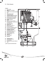
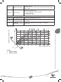
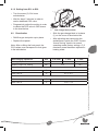
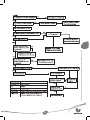
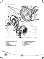
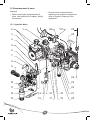
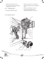
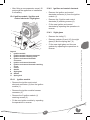
1
CONDENSING BOILER + INSTANTANIOUS HOT WATER
Instructions for use
Installation and servicing
Thema CONDENS F 18 E SB
Thema CONDENS F 24 E
Thema CONDENS F 30 E
Instructions for use
1
General points .........................................................................2
2
Documents ..............................................................................2
3
Safety ......................................................................................2
3.1
3.2
Gas Leak or Fault ..............................................................................2
Safety regulations and recommendations ..........................................2
4
Guarantee / Responsibility ......................................................3
5
Appliance use..........................................................................4
6
Servicing .................................................................................4
7
Recycling.................................................................................4
8
Appliance use: Thema Condens .............................................6
8.1
8.2
8.3
8.4
8.5
8.6
8.7
Control panel .....................................................................................6
LCD display .......................................................................................6
Operating and lighting ........................................................................6
Temperature adjustment ....................................................................7
Time setting ........................................................................................7
Timed central heating setting .............................................................7
«Boost» function ................................................................................7
9
Appliance use: Thema Condens SB .......................................8
9.1
9.2
9.3
9.4
Control panel .....................................................................................8
LCD display ........................................................................................8
Operating and lighting ........................................................................8
Heating temperature adjustment .......................................................9
10
Turn the boiler off ....................................................................9
11
Fault finding.............................................................................9
12
Frost protection .....................................................................10
12.1 Boiler frost protection .......................................................................10
12.2 Installation frost protection ...............................................................10
13
Maintenance/After Sales Service ..........................................10
1
Instructions for Use
Index
1 General points
We accept no liability in case of damage
due to non-compliance of the instructions
of the present manual.
The Thema CONDENS boiler is
an appliance that uses condensing
technology, which recovers heat present
in waste gas.
Thanks to this operating principle,
the boiler consumes less energy and
decreases NOx and CO2 emissions.
3 Safety
3.1
Gas Leak or Fault
• Do not switch on nor switch off the light.
The Thema CONDENS boiler has a
double use (heating + instantanious hot
water).
• Do not activate the electrical switch.
• Do not use the phone in this risky area.
• Do not light up a flame (for example, a
lighter or a match).
This appliance of the room-sealed type
is equipped with a flue exhaust and air
intake for combustion products called
the flue system. This flue principle offers
the possibility to install the appliance in
any room and with no specific ventilation
requirements.
• Do not smoke.
• Turn off the gas emergency control
valve immediatly.
• Open all windows and doors to
ventilate the area.
The installation and the commissioning
of the appliance has to be carried out by
a skilled professional who is responsible
for the compliance of the installation and
the commissioning according to current
regulations.
• Warn any person in the house.
• Inform the Gas Utility company or a
skilled professional.
3.2
You also have to call on a skilled
professional for the maintenance and
repairing of the appliance as well as for
any gas adjustment.
Safety regulations and
recommendations
Please observe the following safety
regulations and recommendations:
• Do not use any aerosols, solvents,
abrasive cleaner, detergents with
chlorine, paint, glue, etc. near the
appliance. Under unfavourable
conditions, these substances can be
very corrosive even for the flue.
Saunier Duval has specially designed
different accessories for your appliance
depending on your installation.
If you want a detailed list, please contact
your supplier or visit our website
www.saunier-duval.co.uk.
• Do not use or store any explosive
material or easily flammable (for
example, petrol, paint, etc.) in the room
where the appliance is situated.
2 Documents
• Never switch off the safety devices and
do not try to adjust these devices as
this could lead to a malfunction.
• Please keep this manual as well as any
documents enclosed with it safe for
future reference.
2
manufacture - if necessary after return to
our factory for examination - on condition
that:
• The appliance was installed by a
qualifled gas installer in accordance
with installation instructions, and all the
relevant codes of practice, standards
and legislation in force.
• Never carry out by yourself
maintenance or repair on the appliance.
• In case of a water leakage, immediately
close the cold water inlet of the
appliance and call a skilled professional
to repair the leak.
• The appliance has been used for
normal domestic purposes and in
accordance with the manufacturer’s
operating and maintenance
instructions.
• Do not break sealed mechanisms.
• Do not modify the technical conditions
close to the appliance, as these are
very important as far as the appliance
safety is concerned.
For example: the minimum clearances
of the external sides.
• The appliance has not been serviced,
maintained, repaired dismantled or
tampered with during the guarantee
period, by anyone other than a
competent person.
• The repair or replacement of parts
during the guarantee period does not
have the effect of extending the period.
Warning!
A heating safety valve with a discharge
pipe is fitted to this appliance. The valve
must not be touched except by a skilled
professional.
This guarantee does not cover:
•
• If the valve discharges at any time,
switch the appliance off and isolate it
from the electrical supply.
Warning!
We advise you to be very careful when
adjusting hot water temperature: water
can be very hot when releasing from the
draw off tap.
Any defects or damage resulting
from incorrect or poor installation,
inadequate servicing, or maladjustment
of the gas or water used.
• Any defects in the system to which the
appliance is connected.
• Any deterioration or maladjustment
following changes in the nature or
pressure of the gas or the water used,
or a change in the characteristics of the
electrical supply voltage.
Notification of any fault should be made
to the appliance installer. No repairs
should be undertaken upon the appliance,
intending it to be covered by the product
guarantee without prior authorisation from
Saunier Duval.
IMPORTANT: The appliance serial number
must be quoted on all correspondence/
contact made with Saunier Duval.
4 Guarantee / Responsibility
Your appliance is guaranteed for a
period of 24 months from the date of
installation or 30 months from the date of
manufacture whichever is the shorter and
covers manufacturing defects only.
We, Saunier Duval, undertake to repair or
replace parts free of charge which
are recognised by us to be of faulty
3
Instructions for Use
• Do not change:
- The appliance,
- The appliance environment,
- Water, air, gas and electric supply,
- Flue system.
This guarantee is in addition to your
statutory and other legal rights, which
will not be excluded or diminished by the
return of the guarantee registration card.
5 Appliance use
Saunier Duval’s appliances are
manufactured according to the latest
technical evolutions and current safety
regulations.
This appliance is used to produce
hot water using gas. Any other use
is considered as inappropriate and is
forbidden.
The manufacturer shall not be responsible
for any damage caused by another
use. In that case the user shall be the
responsible.
6 Servicing
• Clean the case of the appliance with
wet soapy cloth.
• Do not use any abrasive cleaning
product as they could damage the
housing or plastic parts.
7 Recycling
The appliance comprises of many
recyclable parts. The packaging, the
appliance and the content of the package
shall not be thrown together with domestic
waste but disposed of according to the
current regulations.
4
5
Instructions for Use
8 Appliance use: Thema Condens
8.1
Control panel
5
1
time
6
prog
2
3
7
4
Legend
1
Operating mode indicators
2
LCD display
3
Operating mode selection
4
DHW temperature adjustment
5
6
7
8.2
8.3
1
LCD display
21
3
4
• Push switch (6) until the “I” symbol
appears. The display and operational
mode indicator light up.
bar
15
Operating and lighting
• Make sure that:
- The boiler is connected to the
electrical supply.
- The gas service cock is open.
2
3
Operating indicator
On/off switch
Heating temperature adjustment
Multimode display (3):
9
- heating circuit pressure (bar)
- or water temperature in the heating
circuit when heating is on (°C)
Legend
1
Program period of heating on
2
Time display
3
Multimode display
4
Program period of heating off
- or a fault code
Operating indicator:
- Yellow display: flame presence
- Flashing red: fault
6
• Push “MODE” to modify the operating
mode of the boiler. The green LED
indicates the selected mode.
• Use the + or – keys on the “time” side
to set minutes, then press MODE key to
validate.
Domestic hot water +
Timed central heating
8.6
Central heating and
domestic hot water
• Press the MODE key until the green
indicator is in front of the “prog” mode.
Domestic hot water only
• Use the
key on the “prog” side to
select on periods. A black square
appears on the display each time the
key is pressed.
Appliance frost protection
time
Time setting
prog
Heating program setting
Timed central heating setting
• Use the
key on the “prog” side to
program off periods.
Each press on the
and
keys
corresponds to a 30 minute time period.
8.4
Temperature adjustment
• Press on the + and - keys on the “time”
side to move through the program
without modifying it.
8.4.1 Domestic hot water temperature
adjustment
• Press on the MODE key to validate
your heating program.
• Push + or – on the
side to change
domestic hot water temperature.
The ECO symbol remains until 49°C.
8.7
«Boost» function
• Push + or – on the
side to change
water temperature in the heating circuit.
The “boost” function over rides the
program to advance the heating during
periods when the program is off. This
function remains active until the next new
period of heating is reached.
Observation: a quick push on +/- or
/
side displays the temperature value
previously selected.
This function can only be activated in the
“Domestic hot water + timed
central heating” operating mode.
8.4.2 Heating temperature adjustment
8.5
• Press on the
key on the “prog” side
for 5 seconds in order to activate the
“Boost” function.
Time setting
• Press on the MODE key until the green
indicator is in the position in front of the
“time” mode.
The hour section starts flashing.
The activated segments of the heating
program will then flash for 5 seconds.
• Press on the
key on the “prog” side
for 5 seconds to deactivate the “Boost”
function.
• Use the + or – keys on the “time” side
to set present hour, then press MODE
key to validate.
7
Instructions for Use
The minute section starts flashing.
9 Appliance use: Thema Condens SB
9.1
Control panel
1
5
6
2
3
4
Legend
1
Operating mode indicators
2
LCD display
3
Operating mode selection
4
5
6
9.2
9.3
1
LCD display
Heating temperature adjustment
Operating indicator
On/off switch
Operating and lighting
• Make sure that:
- The boiler is connected to the
electrical supply.
- The gas service cock is open.
COD. VAL.
2
• Push switch (6) until the “I” symbol
appears. The display and operational
mode indicator light up.
bar
Multimode display (2):
- heating circuit pressure (bar)
- or water temperature in the heating
circuit when heating is on (°C)
Legend
1
Installer menu
2
Multimode display
- or a fault code.
Operating indicator:
- Yellow display: flame presence
- Flashing red: fault
8
The appliance is no longer supplied
with electric power.
We advise you to turn off the appliance
gas supply if you leave home for a long
period.
Central heating
Appliance frost protection
9.4
11 Fault finding
When a fault occurs, the operating
indicator flashes red and the display
shows a fault code, symbolized by the
letter F followed by a number, for example
F1. As a user, you can act only in the
following cases. If other codes appear
than those listed in the following table, you
must contact a skilled professional.
Heating temperature adjustment
• Push + or –
to change water
temperature in the heating circuit.
Observation:
A quick push on +/- displays the
temperature value previously selected.
Warning !
Never try to service or repair the appliance
by yourself and only start the appliance
once a skilled professional has repaired
the fault.
10 Turn the boiler off
• Push switch (6) until the “O” symbol
appears.
Fault code
Cause
Corrective action
The LCD display is
off.
Power failure
Check the mains power supply is on and that
the appliance is switched on at the spur or
socket. The appliance starts automatically
once the power supply is on. If the fault
persists, please contact a skilled professional.
F1 or F4
Ignition fault
Switch off the boiler
Wait 5 seconds and then start the boiler again.
If the fault continues, please contact a skilled
professional.
F2
Air flow failure
The safety system shuts off the appliance.
Please contact a skilled professionnal
F5
Overheating fault
Please contact a skilled professionnal
The operating and
pressure indicator
flashes
Insufficient water
pressure in the system
(<0.5 bar)
Open the 2 blue taps situated under the boiler
simultaneously until you obtain a pressure
between 1 and 2 bars on the indicator. If you
have to fill often this might be caused by a
leak in your appliance or system. In this case,
contact a skilled professional to check the
boiler and system.
Other defects
Please contact a skilled professionnal
9
Instructions for Use
• Push “MODE” to modify the operating
mode of the boiler. The green LED
indicates the selected mode.
12 Frost protection
13 Maintenance/After Sales Service
12.1 Boiler frost protection
Please note that incorrect servicing can
affect the safety of the appliance and can
lead to injury.
In case of frost risk, do as follows:
• Make sure the boiler is supplied with
electrical power and gas.
To ensure the continued efficient and
safe operation of the appliance it is
recommended that it is checked and
serviced as necessary at regular intervals.
The frequency of servicing will depend
upon the particular installation conditions
and usage, refer to guarantee registration.
• Select the
operating mode on the
control panel.
The frost protection system orders the
pump to start as soon as the temperature
in the heating circuit falls below 8°C. The
pump stops as soon as the temperature of
the water contained in the heating circuit
reaches 10°C.
If the temperature in the heating system
falls below 5°C, the burner ignites until it
reaches 35°C.
If this appliance is installed in a rented
property there is a duty of care imposed
on the owner of the property by the current
issue of the Gas Safety (Installation and
Use) Regulations, Section 35. Servicing/
maintenance should be carried out by
a competent person in accordance with
the rules in force in the countries of
destination. To obtain service, please call
your installer or Saunier Duval service.
12.2 Installation frost protection
• If you leave home for a few days, select
the minimum heating temperature on
the control panel of the boiler and just
decrease the setpoint temperature on
your room thermostat.
• If you leave home for a long period, see
chapter “Draining of the appliance” in
the installation manual.
10
Installation and servicing
1
Comments on the instructions...............................................13
2
Appliance description ............................................................13
2.1
2.2
2.3
Data label .........................................................................................13
Mandatory WARNING for EEC countries .........................................13
Block diagram .................................................................................14
3
Appliance location .................................................................15
4
Safety instructions and regulations .......................................15
4.1
4.2
Safety instructions ............................................................................15
Regulations ......................................................................................16
5
Appliance installation ............................................................17
5.1
5.2
5.3
5.4
5.5
5.6
5.7
5.8
5.9
5.10
Recommendations before mounting ................................................17
Thema CONDENS dimensions .......................................................18
Thema CONDENS SB dimensions .................................................18
List of delivered equipment ..............................................................18
Fixing to the wall ..............................................................................18
Gas and water connection ...............................................................19
Connection to the condensate trap ..................................................21
Flue connection ................................................................................22
Electrical connection ........................................................................24
Wiring diagram .................................................................................26
6
Commissioning......................................................................28
7
Specific adjustments .............................................................28
7.1
7.2
Heating circuit adjustment ................................................................28
Access to the boilers technical data
(for professional and After Sales Service use only) .........................30
8
Draining of the appliance ......................................................32
8.1
8.2
Heating circuit ..................................................................................32
Domestic Hot Water circuit ..............................................................32
11
Installation and servicing instructions strictly reserved for qualified gas installers
Index
9
Gas conversion .....................................................................32
9.1
9.2
Maximum power setting .................................................................32
Reactivation .....................................................................................33
10
Fault finding...........................................................................34
11
Control / Commissioning .......................................................36
12
User information ....................................................................36
13
Spare parts............................................................................36
14
Servicing ...............................................................................36
14.1
14.2
14.3
14.4
14.5
Casing ..............................................................................................36
Removable plate / Silencer ..............................................................37
Condensate trap ..............................................................................37
Hydraulic block .................................................................................38
Combustion block ............................................................................40
15
Remplacement of parts .........................................................42
15.1
15.2
15.3
15.4
15.5
Hydraulic block .................................................................................42
Combustion block ............................................................................44
Expansion vessel .............................................................................46
Ignition module / Ignition and control electrode / Sight glass ...........47
Control panel ....................................................................................48
16
Technical data .......................................................................50
12
1 Comments on the instructions
Member States relating to appliances
burning gaseous fuels.
• Please give all of the instructions to
the user. The user shall keep them for
future reference.
We accept no liability in case of damage
due to the non-compliance of the
instruction manual.
- Directive 73/23/EEC on the
harmonisation of the Laws of the
Member States relating to electrical
equipment designed for use within
certain voltage limits.
- Directive 89/336/EEC on the
approximation of the Laws of
the Member States relating to
electromagnetic compatibility.
IMPORTANT. With regards to the
Manual Handling Operations, 1992
Regulations, the following lift operations
are recommended as the appliance weight
exceeds a one-man lift.
2 Appliance description
Data label
The data label certifies the origin where
the product was manufactured and the
country for which it is intended.
Warning! The appliance shall only be used
with the gas types indicated on the data
label.
2.2
• Clear the route before attempting the
lift.
• Ensure safe lifting techniques are used
- keep back straight - bend using legs.
Mandatory WARNING for EEC
countries
• Keep load as close to body as possible.
This appliance is designed, approved and
inspected to meet the requirements of the
intended market. The data label indicates
where the product was manufactured and
the country for which it is intended.
• Do not twist - reposition feet instead.
• If two persons performing lift, ensure
co-ordinated movements during lift.
• Always use assistance if required.
This appliance meets the requirements
of Statutory Instrument, No. 3083 The
Appliance (Efficiency) Regulations,
and therefore is deemed to meet the
requirements of Directive 92/42/EEC
on the efficiency requirements for new
hot water appliances fired with liquid or
gaseous fuels.
Manufacturer’s instructions must not be
taken as overriding statutory requirements.
Reference in these instructions to British
standards and statutory regulations/
requirements apply only to the United
Kingdom. For Ireland the current edition of
I.S.813 «Domestic Gas Installations» must
be used.
This appliance certificated to the
current issue of EN 483: 2000 for
performance and safety. It is important
that no alteration is made to the appliance,
without permission, in writing, from
Saunier Duval. Any alteration that is
not approved by Saunier Duval could
invalidate the warranty and could also
infringe the current issue of the Statutory
Requirements.
Type test for purposes of Regulation 5
certified by: Notified body 0063. Product/
production certified by: Notified body
0086.
The CE mark on this appliance shows
compliance with:
- Directive 90/396/EEC on the
approximation of the laws of the
13
Installation and servicing instructions strictly reserved for qualified gas installers
2.1
2.3
Block diagram
Legend
1
Flue outlet
2
Main heat exchanger
3
Burner
4
Ignition and control electrode
5
Fan
6
Gas control valve
7
Condensate trap
8
Overheat safety thermostat
9
Heating expansion vessel
10 Heating return thermistor
11 Heating flow thermistor
12 Ignition module
13 Pump
14 Water pressure sensor
15 Domestic plate to plate heat
exchanger (*)
16 Three way valve
17 Drain cock
18 DHW flow sensor (*)
19 Filling system (*)
20 Filter on cold water inlet (*)
21 Heating isolating valve
22 Domestic cold water
isolating valve (*)
23 Heating isolating valve
24 Gas isolating valve
25 Heating safety valve
26 Thermal fuse
27 Silencer
28 Filling tap (*)
29 By-pass
A
B
C
D
E
29
Heating return
Cold water inlet (*)
Heating flow
Domestic hot water outlet (*)
Gas
(*) Not required for SB models
14
3 Appliance location
Any alteration not approved by Saunier
Duval, could invalidate the certification,
appliance warranty and may also
infringe the current issue of the statutory
requirements.
• This appliance is not suitable for
outdoor installation.
• This appliance may be installed in any
room, although particular attention is
drawn to the installation of an appliance
in a room containing a bath or shower
where reference must be made to the
relevant requirements. In GB this is the
current I.E.E. WIRING REGULATIONS
and BUILDING REGULATIONS.
4.1
Safety instructions
If the gas pressure at the input of the
appliance is outside the range specified,
you shall not start the appliance. If the
cause of the problem cannot be found
nor solved, please contact the Gas Utility
company.
• In IE reference should be made to the
current edition of I.S.813 «Domestic
Gas Installations» and the current ETCI
rules.
Warning! Incorrect installation can cause
electric shock or appliance damage.
- Never use a wire brush or stiff-bristle
scrubbing brush to clean the heat
exchanger as this could damage the
appliance.
• The appliance must be mounted on a
flat wall, which is sufficiently robust to
take its weight.
- Under no circumstances must the User
interfere with or adjust sealed parts.
Under Section 6 of The Health and
Safety at Work Act 1974, we are required
to provide information on substances
hazardous to health.
The adhesives and sealants used in this
appliance are cured and give no known
hazard in this state.
• The appliance is room sealed, so when
it is installed in a room or space, a
permanent air vent is not required.
• Do not install the appliance above
another appliance that could damage
it (for example, above a cooker that
might emit steam or grease) or in a
room, which has a lot of dust in the
atmosphere which is corrosive.
In the event of the appliance overheating
the safety devices will cause a safety
shutdown. If this happens, call your
installation/servicing company.
4 Safety instructions and
regulations
Warning! This appliance must be
earthed. This appliance must be wired in
accordance with these instructions. Any
fault arising from incorrect wiring cannot
be put right under the terms of the Saunier
Duval guarantee.
This appliance is tested and certificated
for safety and performance. It is, therefore,
important that no alteration is made to the
appliance, without permission, in writing,
from Saunier Duval.
15
Installation and servicing instructions strictly reserved for qualified gas installers
- When making the connections, locate
the sealing washers properly so as to
avoid any gas or water leakage.
• Make sure you keep an appropreate
distance between the sides of the
appliance to ensure total accessibility
for servicing.
The following safety instructions must
be imperatively followed during the
maintenance and the replacement of
spare parts.
In GB the installation of the appliance
must be carried out by a competent
person as described in the following
regulations:
• Stop the appliance (see chapter
“Deactivation” of the Instructions for
use).
- The manufacturer’s instructions
supplied.
- The Gas Safety (Installation and Use)
Regulations.
• Disconnect the appliance from the
mains power supply with the socket or
the double-pole switch (with a minimum
gap of 3mm for both poles).
- The appropriate Buildings Regulations
either The Building Regulations, The
Building Regulations (Scotland), The
Building Regulations (Northern Ireland).
• Turn off the gas control valve.
- The Water Fittings Regulations or
Water byelaws in Scotland.
• Close the shut off valves located on the
connection sockets.
- The Health and Safety at Work Act,
Control of Substances Hazardous to
Health (COSHH).
• Drain the appliance when you want
to change the hydraulic parts of the
appliance.
- The Current I.E.E. Wiring Regulations.
Where no specific instructions are given,
reference should be made to the relevant
British Standard Code of Practice.
In IE, the installation must be carried out
by a competent person and installed in
accordance with the current edition of
I.S.813 «Domestic Gas Installations»,
the current Building Regulations and
reference should be made to the current
ETCI rules for Electrical Installation.
• Let the appliance cool down before
undertaking any maintenance
operation.
• Protect all the electrical components
from water when you achieve any
operations.
• Use only new O-rings and gaskets.
• After having compleated work on gas
carrying components, check their
tightness.
In GB the following Codes of Practice
apply: BS4814, BS6798, BS5440 Part 1
and 2, BS5546 Part 1, BS5449, BS6891,
BS6700, BS7074 Part 1 and 2, BS7593,
BS7671.
In IE: I.S.813, BS5546, BS 5449, BS
7074, BS 7593.
• When the replacement work is
compleated, perform an operation test
of the replaced parts and the appliance.
4.2
Regulations
When installing and commissioning the
appliance, the regulations below shall be
observed in their current version:
In your own interests and that of safety, it
is the Law that ALL gas appliances must
be installed by a competent person only,
in accordance with the current issue of the
following regulations.
Where no British Standard exists,
materials and equipment should be fit
for their purpose and of suitable quality
and workmanship. The installation of
this appliance must be carried out by
a competent person in accordance
the rules in force in the countries of
destination. Manufacturer’s instructions
16
must not be taken as overriding statutory
requirements.
(see chapter “Heating circuit adjustment”).
The system will be calculated according
to the flow corresponding to the power
that is really required without taking into
account the maximum power that the
boiler can supply. Nevertheless, we advise
you to have a flow big enough so that the
temperature difference between outgoing
and return is under or equal to 20°C. The
minimum flow rate is indicated in the
chapter “Technical Data” at the end of this
instruction manual.
If the appliance is to be installed in a
timber frame building it should be fitted
in accordance with the Institute of Gas
Engineers document IGE/UP/7/1998. If
in doubt seek advice from the local gas
undertaking or Saunier Duval.
5 Appliance installation
All the dimensions in this chapter are
expressed in mm.
Recommendations before
mounting
5.1.1 Domestic hot water circuit design
The circuit should be designed to avoid
any unnecessary flow losses (decrease
the number of elbows).
Total water volume accepted by the
heating circuit depends, amongst
other things, on the cold static load.
The expansion tank fitted in the boiler
is delivered set in plant (see chapter
“Technical Data” at the end of this
instruction manual). At commissioning, it is
possible to change this pressure in case of
a more larger static load. We advise you
to provide a drain valve at the lowest point
of the system.
The boiler will operate with a minimum
supply pressure but with a low flow.
Optimum performance will be achieved
with a pressure of 1 bar.
5.1.2 Heating circuit design
The Thema CONDENS boilers can
be used for any kind of installation: serial
or derivated double tube, single tube, hot
floor, etc...
Heating surfaces can be made up with
heaters, convectors or unit heaters.
If thermostatic radiator valves are used,
we advised you not to fit in a room where
a room thermostat is fitted.
• If the boiler is not immediately installed,
protect all the pipe fittings so as to
avoid that any plaster element or paint
could impede the connection.
Warning: We advise you to add an
inhibitor to the heating circuit water
(according to the manufacturer’s
recommendations) to avoid gas production
and oxide formation.
The pipework sections should be fixed by
using the following flow/pressure curve
17
Installation and servicing instructions strictly reserved for qualified gas installers
5.1
The piping route should be designed in
such a way that it avoids any air locks
and make purging of gas from the system
easier. Bleeders should be placed at each
high point of the system as well as on any
radiators.
5.1.3 Water treatment
5.3
In the case of an existing installation, it is
Essential that prior to installing the new
boiler the system is thoroughly flushed.
For optimum performance after
installation of a new system, the boiler and
its associated central heating system
should also be flushed.
Flushing should be carried out in
accordance with BS7593: 1992 using a
cleanser such as Sentinel X300 or X400,
Fernox Superfloc or Salamander corrosion
guard cleaner.
215
742
For long-term corrosion protection, after
flushing, an inhibitor suitable for stainless
steel heat exchangers should be used,
refer to the current issue of BS 5449 and
BS 7593 on the use of inhibitors in central
heating systems. Examples are Sentinel
X100 Fernox or Salamander corrosion
guard inhibitor.
5.2
Thema CONDENS SB dimensions
410
Thema CONDENS dimensions
5.4
370
List of delivered equipment
The boiler is delivered in one package:
- One documentation pack:
- 1 user and installation manual
- 1 guarantee envelope
- 1 Wiring diagram
- 1 gas conversion label
215
- One parts pack:
- 1 drain tube
- 2 filling loop extensions (*)
- 1 connection pack + wall template
- 1 gasket+ flow limiter pack
- 1 valve pack
(*) Not required for SB models
742
The flue is supplied separatly and will
depend upon the configuration of the
installation.
410
5.5
370
Fixing to the wall
• Make sure the material you use fits
those of the appliance.
18
5.6
• Chose the location of the appliance.
See chapter “Appliance location”.
The hanging bracket will be adapted to
the features of the bearing wall and will
have to take into account the weight of the
boiler filled with water.
• Before undertaking any operation,
carefully clean the pipes with an
appropriate product in order to remove
impurities such as filings, welds,
different oils and greases that may be
present.
These foreign bodies may enter the
boiler and disrupt the operation.
• Drill the holes for the fixing screws
in accordance to the diagram below
and to the size of the wall template
delivered with the appliance.
• Do not use any solvents that could
damage the heating circuit.
=320=
Ø105
The pipe from the heating safety
discharge valve must not discharge above
an entrance, window or any type of public
access area.
min.
• Only use the genuine seals delivered
with the appliance.
• Check that there is no leakage. Repair
if need be.
Take the short safety discharge tube,
union nut and seal, supplied loose in
the boiler fittings pack.
GAZ
GAS
70
38
37
102
70
• Place the boiler above the hanging
bracket.
This must be extended, using not less
than 15mm o.d. pipe, to discharge, in a
visible position, outside the building, facing
downwards, preferably over a drain.
• Slowly lower the boiler.
The pipe must have a continuous fall
and be routed to a position so that any
discharge of water, possibly boiling, or
steam cannot create any danger to
persons, damage to property or external
electrical components and wiring.
• Set the seals on the different pipe
fittings.
• Make connections to boiler, gas,
water and heating cocks with the tube
assemblies supplied in piping pack.
• Do not forget to connect the 2
filling loop extensions on the 2
filling taps. (*)
(*) Not required for SB models
To ease future servicing it is advisable to
use a compression type fitting to extend
the safety discharge valve tube.
19
Installation and servicing instructions strictly reserved for qualified gas installers
• Take care when soldering pipes as the
heat could damage the seals and cause
leakage. Fit washers after joints have
cooled.
5
811 748
Gas and water connection
1
4
2
5
16
wa
3
ll
6
205
4
,5
7
15
8
9
10
2
8
13
14
6
12
9
1
A
11
Legend
Connection pack:
A
Pressure test point
2
Heating pipe: angular bush to weld Ø
22 + nut 3/4" (x2)
4
Gasket 3/4" (x3)
5
Cold water inlet pipe (*): angular bush
to weld Ø 15 + nut 1/2"
6
Gasket 1/2" (x4)
9
Heating isolating valve
10 Cold water inlet isolating valve (*)
11 Gas inlet isolating valve
12 Domestic hot water outlet pipe (*):
angular bush to weld Ø 15
13 Nut 3/4" (*)
14 Gas pipe: angular bush to weld Ø 15 +
nut 1/2"
4
16
Hanging bracket
Gasket + limiter pack:
1
Flat gasket (x2)
7
Cold water flow limiter (*)
8
Gasket 3/4" (x5)
Valve pack:
1
Flat gasket
3
Nut
15 Evacuation pipe for heating safety
valve
(*) Not required for SB models
20
5.7
Connection to the condensate
trap
5.7.2 Condensate drain
5.7.1 Filling of the condensate trap
1
3
2
3
1
2
3
4
Legend
1
Condensate trap
2
Filling trap
3
Expansion vessel valve
• Connect the condensate outlet (3) to a
discharge system leading to the sewer.
• Unscrew the filling trap (2) located
under the condensate trap.
• Fill the trap 3/4 full with water (2).
• Replace the filling trap (2) in the
condensate trap (1).
OK
Warning ! The condensate trap must be
pre-filled before the first operation of the
boiler.
OK
21
Installation and servicing instructions strictly reserved for qualified gas installers
Legend
1
Condensate trap retaining clips
2
Condensate trap
3
Condensate outlet
4
Outlet siphon
5.8
Flue connection
Different flue outlet configurations can be
carried out.
• Consult your supplier for more
information about the other possibilities
and associated accessories.
Warning! You can only use flue
accessories approved for the Thema
CONDENS.
4.4 %
44mm / 1 M
• Whatever the kind of flue system
chosen, observe the minimum
distances indicated in the chart below
to position the flue terminals.
• Ensure a slope of 44 mm/m between
the elbow and the terminal extremity to
enable the return of condensate to the
appliance.
S
R
22
5.8.1 Horizontal concentric flue
Ø 60/100
(C13 type installation)
Position of the flue
mm
terminal
Horizontal flues
directly below an opening,
A
air brick,
300
opening windows
above an opening, air brick,
B
300
opening windows
horizontally to an opening,
C
air brick,
300
opening windows
D
below gutter, drain/soil pipe
25
E
below eaves
25
F
below a balcony or car port
25
from vertical drain pipes
G
25
and soil pipes
from internal/external
H
25
corners
to a boundary alongside
H*
300
the terminal
above adjacent ground or
I
300
balcony level
from surface or a boundary
J
600
facing the terminal
from opening (door/
L
window) in car port
1200
into dwelling
M
vertical from a terminal
1500
N
horizontally from a terminal 300
Vertical flues
P
from another terminal
600
Q
above roof level
300
from adjacent opening
R
1000
window
S
from adjacent wall to flue
300
Position
L
1
72
Maximum flue index: 150 Pa
This value is reached with the length of
the maximum duct (L) + 1 90° elbow.
Flue model
Ø 60/100
Max. length
5.5 m
Every time a 90° elbow is used (or 2 off
45°), the length (L) should be reduced by
1 m.
A Plume management kit can be installed
at the extremity of the duct.
• Refer to the instructions sheet of the
accessory and take it into account the
following length:
Length L2 = L
Length L1
0.5
1
2
3
4
8
7
5.5
3.5
2
Every time a 90° elbow is used (or 2 off
45°), the length (L1) should be reduced by
2 m.
23
Installation and servicing instructions strictly reserved for qualified gas installers
Legend
1
Gasket
5.8.2 Vertical concentric flue
Ø 60/100
(C33 type installation)
This value is reached with 2 elbows, the
separator and the maximum duct length
(L1+L2) of 40 m.
Every time an extra 90° elbow is used (or
2 off 45°), the length (L) should be reduced by 2 m.
5.9
Electrical connection
Warning! Incorrect installation can cause
electric shock or appliance damage.
• Connect the power cable of the boiler to
the 230 V single-phase + earth network.
L
• Observe the live and neutral connection
on the boiler.
• Do not use cable over 10 mm in
diameter for electrical connections.
Important: Electrical connection of the
appliance must be made only by a skilled
professional.
Maximum flue index: 150 Pa
This value is reached with the length of
the maximum duct (L) + 1 90° elbow.
Flue model
Ø 60/100
Isolation should be by a double pole
switched fused spur box, with a minimum
gap of 3mm for both poles.
Max. length
6.5 m
The fuse of the PCB must be connected to
the neutral.
Every time an extra 90° elbow is used (or
2 off 45°), the length (L) should be reduced at by 1 m.
5.9.1 Access to electrical connections
1
5.8.3 Twin flue 2 x Ø 80
(C53 type installation)
LL11
L2
188
2
Legend
1
Access on factory connection side
2
Access on installer connection side
Maximum flue index: 150 Pa
24
• Open the installer connection side (2) to
carry out the electrical connections.
• Respect passage (2) for low voltage
cables and (3) for high voltage cables.
5.9.2 Connection to the PCB
5.9.4 External controls connection
1
3
2
30 mm max.
Legend
1
Terminal block
2
Electrical wires
3
Sheath
5
1
Warning ! When connecting electrical
cables to the terminal block on the PCB:
4
• Keep a 30 mm maximum distance
between the terminal block (1) and the
stripped sheath (3).
3
• Otherwise, fasten the electrical wires
(2) together with a cable tie.
Legend
1
Neutral
2
Room Thermostat
3
Live
4
Frost Protection
5
Link wire
• Secure the cables with the electrical
box cable clamp.
5.9.3 Separation of high and low
voltage cables
Important ! Remove link wire (5) when
fitting external controls.
1
2
3
Legend
1
Main board
2
Passage for high voltage
3
Passage for low voltage
25
Installation and servicing instructions strictly reserved for qualified gas installers
2
5.10 Wiring diagram
16
15
1
14
2
3
4
5
13
6
12
7
11
10
9
8
26
Legend
1
Ignition module
2
Ignition and control electrode
3
Heating return thermistor
4
Overheat thermostat
5
Pump
6
Main board
7
User interface
8
On/Off switch
Fuse
Water flow sensor
Three way valve
Water pressure sensor
Heating flow thermistor
Gas valve
Fan
Thermal fuse
Installation and servicing instructions strictly reserved for qualified gas installers
9
10
11
12
13
14
15
16
27
6 Commissioning
7 Specific adjustments
• Slide the switch until the “I” symbol
appears.The display and operating
mode indicator light up: the boiler is
ready to run.
7.1
Heating circuit adjustment
This flow rate will be adjusted according to
the system calculations.
When it is delivered, the (1) integrated
bypass screw is open by half a turn.
• Open the isolating valves located on
the pipes: they will be placed in the
direction of the flow.
• Open the auto air vent on the pump as
well as the automatic bleeders of the
system.
1
• Open the two blue filling loop valves
situated under the boiler simultaneously
until you obtain a 2 bar pressure on the
indicator.
Legend
1
Bypass screw
• Bleed each radiator to remove the air,
re-tighten bleed screws.
• Depending on the requirements, adjust
this screw (for example, screw for
closing) in order to fit the available
pressure head to the system energy
loss according to the output/pressure
curve.
• Leave the cap on the pump auto air
vent open.
• Flush the domestic hot water system by
openning the hot water taps for several
minutes.
• Make sure the display indicates a
system pressure of between 1 and 2
bars. Re-fill system as necessary.
1
• Operate the appliance for at least 15
minutes on heating with a heating
temperature equal or greater to 50°C.
• Flush the domestic hot water system by
openning the hot water taps for several
minutes.
2
3
Legend
1
Speed selector of pump
2
Speed I
3
Speed II
• Make sure the display indicates a
system pressure of between 1 and 2
bars. Re-fill system as necessary.
• Turn the selector (1) to choose pump
speed I or II in relation to the output/
pressure curve.
28
Available pressure (kPa)
between heating flow and return
Output/pressure curve ThemaCondens F 24 E
70
60
50
40
1
30
2
6
20
5
3
4
10
9
Legend
Speed II
1
By-pass fully shut
2
Open 1/2 turn
3
Open 1 turn
Speed I
4
By-pass fully shut
5
Open 1/2 turn
6
Open 1 turn
Available pressure (kPa)
between heating flow and return
Output/pressure curve ThemaCondens F 18 E SB and F 30 E
70
60
50
1
40
2
30
6
20
3
5
4
10
9
500
1400
1000
Heating circuit flow rate (l/h)
Legend
Speed II
1
By-pass fully shut
2
Open 1/2 turn
3
Open 1 turn
Speed I
4
By-pass fully shut
5
Open 1/2 turn
6
Open 1 turn
29
Installation and servicing instructions strictly reserved for qualified gas installers
1000
1400
Heating circuit flow rate (l/h)
500
7.2
Access to the boilers technical
data (for professional and After
Sales Service use only)
• Once again press the “MODE” key to
display the first parameters menu, i.e.
the heating maximum power (menu
COD.1).
The access to the boilers technical data
allows you to make some adjustments and
to analyse potential malfunctions.
• When the menu «COD.1» appears on
the display, press on the + or – keys
on the
or
side to get to the next
menu or press on the MODE key if you
wish to change this parameter.
For example, you can adjust the maximum
power of the boiler in heating mode on all
the values included between the powers
indicated in the chart at the end of this
manual. This makes it possible to adapt
the power supplied to the real needs of
the system so as to avoid any over-power,
while maintaining a high efficiency.
Note: the heating power decrease has no
effect on the domestic hot water power.
• In parametes mode, select the desired
value by using the + or – keys on the
or
side.
• Validate by pressing the “MOD” key and
return to the initial menu.
• Restart the preceding operations in
order to change other parameters.
Do as follows:
Note: the indicator goes back to its normal
position after 10 minutes without any
operation or after having pressed the
“MODE” key for more than 3 s.
• Press for more than 10 seconds on
the “MODE” key to access the setting
menu.
• When “0” and “ ” appear, use the
keys + or - on the
or
side until
“96” appears on the indicator.
N° menu
Title
Action
COD. 1
maximum heating
power
Press the +
- keys to set the required value
(factory setting for Thema CONDENS F 18 E SB: 18
factory setting for Thema CONDENS F 24 E and F 30 E: 15)
COD. 2
flue configuration
No adjustment required for this kind of boiler. Flue codes have
no effect on the boiler operation.
COD. 3
minimum heating
temperature
Select a value: 28°C, 38°C, 50°C, 55°C, or 70°C
(factory setting: 28°C)
COD. 4
maximum heating
temperature
Select a value: 50°C, 73°C, or 80°C
(factory setting: 73°C)
pump mode
Select an operating mode:
1 - intermittent with room thermostat (factory setting)
2 - intermittent with burner
3 - permanent
COD. 5
The two following menus require an outdoor sensor:
COD. 6
heating curve
Choose a heating curve from the following 10:
0.2 / 0.6 / 1.0 / 1.2 / 1.5 / 2.0 / 2.5 / 3.0 / 3.5 / 4.0
(See graphic below)
30
COD. 7
COD. 8
heating curve base
Choose a value:
15°C / 16°C / 17°C / 18°C / 19°C / 20°C / 21°C / 22°C / 23°C
/ 24°C / 25°C
burner forcing
Select an operating mode:
0 - normal operation. (factory setting)
1 - forcing at P. mini.
2 - forcing at P. maxi.
COD. 8 menus and following would only be used by After Sales Service Engineers.
COD. 23
select product code
Select a value between 0 and 199.
COD. 24
set the offset on the
minimum fan speed
Select a value between 0 and 99 (99 = 990 rpm).
(no 10 rpm)
COD. 25
rmaximum
condensation power
Select a value between 0 and 99 (99 = -1485 rpm)
(no 15 rpm)
Heating curve
3.5
3.0
2.5
2.0
1
1.5
80
1.2
70
1.0
60
25
0.6
50
40
0.2
30
20
2
Outdoor temperature (°C)
15
Legend
1
Menu 6 setting
2
Menu 7 setting
31
Installation and servicing instructions strictly reserved for qualified gas installers
Heating flow temperature (°C)
4.0
90
8 Draining of the appliance
1
2
8.1
Heating circuit
• Turn on the drain cock (1) provided at
the system low point.
3
• Provide an air intake by opening a
radiator bleed screw.
Legend
1
Plug
2
Test point
3
Maximum power setting screw.
• Take off cap (1) then insert a sampling
tube in the test point (2) in the flue
system.
1
9.1
Maximum power setting
- In domestic hot water with CO2:
• In order to drain only the water in the
boiler, first shut off the heating flow and
return isolating valves.
8.2
• Fully open a hot water tap.
• Wait for 2 minutes or so, until the CO2
reading has stabilized.
Domestic Hot Water circuit (*)
- In heating with CO2:
• Turn off the water cock of the system.
• Create an air intake by turning on a
hot water tap or open the DHW safety
valve.
• Adjust the boiler on «Burner forcing at
P. max.» using menu COD.8 described
in chapter «Access to the boilers
technical data».
(*) Not required for SB models
• Perform a heating demand.
9 Gas conversion
• Wait for 2 minutes or so, until the CO2
reading has stabilized.
For operation with LPG, some adjustments
must be made on the gas valve
9.1.1 Setting from G20 to G31
• First of all remove the front panel.
• Turn the screw (3) 2 full turns
clockwise.
• Connect a CO2 analyser to the flue
elbow.
• Wait for about 2 minutes in order to
read a stabilized CO2 value.
• Progressively adjust the setting in order
to obtain the CO2 value in G31 shown
in the chart below.
32
9.1.2 Setting from G31 to G20
1
• Turn the screw (3) 2 full turns
anticlockwise.
• Wait for about 2 minutes in order to
read a stabilized CO2 value.
• Progressively adjust the setting in order
to obtain the CO2 value in G20 shown
in the chart below.
• Stick the gas change label in its place
(1) on the cover of the electric box.
2
Reactivation
• Refit flue gas test point cap in place.
• After adjusting and remounting the
sealed panel, switch the COD. 8 menu
“burner forcing” back to its normal
operating mode (factory setting = 0) if
maximum power has been adjusted in
heating mode.
• Replace front panel.
Note: After re-fitting the front panel, the
CO2 values must correspond to that given
in the table below.
Gas changing adjustment
Unit
F 18 E SB
F 24 E
F 30 E
Heating output max. hot water
kW
-
24
29.6
Heating output min. heating
kW
18.3
24.1
G20
CO2 case on
%
9 +/- 0.2
CO2 case off
%
9.2 +/- 0.3
CO2 case on
%
10.1 +/- 0.2
CO2 case off
%
10.3 +/- 0.3
G31
33
Installation and servicing instructions strictly reserved for qualified gas installers
9.2
Legend
1
Gas change label position
10 Fault finding
Important: a central heating system cannot
operate efficiently if it is not filled with
water and if the air it contains at first has
not been completely removed. If those
requirements are not fulfilled, some noise
originated by the water boiling inside the
boiler and noise of water chute inside the
radiators could appear.
You will find the list of some fault codes in
the operating instructions.
The faults described in this chapter should
be carried out by a skilled professional
and if need be by SAUNIER DUVAL’s After
Sales Service.
Code Description
F1, F4
Ignition fault, boiler fialed
to light
F5
Overheat fault
F6
F7
F9
F10
F11
F13
F16
F18
F19
F20
F23
F26
F28
F29
Central heating flow
thermistor fault
DHW thermistor fault
Water pressure sensor
fault
Central heating return
thermistor fault
User interface connection
fault
Main board connection
fault
Flame detection fault
(flame presence for more
than 5 seconds after
burner stopped)
User interface fault
Central heating thermistor
unplugged
Possible cause
No gas / Insufficient gas
Incorrect gas valve adjustment
Electrode ignition lead defect
Electrnic igniter defective
Check air inlet duct and connections to igniter unit
Overheat stat operated
Maximum temperature exceeded
Check thermistor connections
Air in system with thermistor at maximum setting
Faulty overheat stat connection
Thermistor cable defective/broken
Thermistor faulty
Check that thermistor attached correctly to pipe
Faulty sensor connection
Check wiring
Thermistor cable defective/broken, thermistor faulty
Check that thermistor attached correctly to pipe
Check wiring between mainboard and user interface
Main board defective
Check connection and wires
Gas valve defective
Faulty user interface
Thermistor cable defective/broken, thermistor faulty
Check that thermistor attached correctly to pipe
Incorrect user interface or main board
Software incompatibility
Incorrect product code
Water circulation fault
Possible pump failure
Maximum delta
Water circulation fault
temperature (flow - return) Check central heating flow and return connection
Permanent drift between
Check central heating flow and return thermistor connection
flow sensor and return
Thermistor defective
sensor
Thermal fuse
Replace the heat exchanger
34
35
Installation and servicing instructions strictly reserved for qualified gas installers
11 Control / Commissioning
spare parts from SAUNIER DUVAL should
be used when repairing and servicing the
appliance.
Once the appliance is installed, check
whether it runs:
• Only use original spare parts.
• Start the appliance according to the
indications of the operating instructions
and check whether it runs.
• Make sure that these parts have been
correctly assembled with regards to
their position and basic sense.
• Check the appliance for leaks (gas
and water) and eliminate any leakage
found.
14 Servicing
Warning!
• Check that the ignition is correct and
that the flames of the burner are
uniform.
• Before starting the maintenance of the
appliance, read carefully the chapter
“Safety instructions”.
• Check that the flue exhausts properly.
• Check the whole control and safety
devices, their setting and their
operating state.
14.1 Casing
12 User information
The user should know how to use the
appliance.
• Explain to the user the appliance
operating principles and demonstrate if
required.
1
• Have a look at the operating
instructions together and answer any
questions if need be.
2
3
• Give the user all of the manuals and
documents concerning the appliance
and tell the user to keep them near the
appliance.
Legend
1
Insulation
2
Front panel
3
Front panel retaining screws
• Explain more precisely the safety
principles they should observe.
• Remove the 2 retaining screws (3) from
the front panel.
• Remind the user to regularly service the
appliance.
• Pull gently on the front panel (2) from
the bottom and lift up to remove.
13 Spare parts
In order to guarantee a long-lasting
operating of the parts of the appliance
and keep it in good condition, only original
36
14.3 Condensate trap
14.2 Removable plate / Silencer
1
1
2
3
2
3
3
4
Legend
1
Upper silencer
2
Upper silencer retaining screw
3
Lower silencer
4
Removable plate
14.2.1
• Drain the filling siphon of the
condensate trap (see chapter on “Filling
the condensate trap”).
Removable plate
• Disconnect the outlet pipe located
under the condensate trap (2).
• Remove the removable plate (4) by
pulling towards you.
14.2.2
• Disconnect the condensate trap pipe
located under the combustion chamber
(see chapter on “Spare parts”).
Silencer
• Remove the condensate trap by
releasing the retaining clips (1) and
taking care not to spill any liquid.
• Remove the removable plate (4).
• Disconnect the lower silencer (3).
• Remove the upper silencer retaining
screw (2).
• Clean the pipes and remove any debris.
• Clean the condensate trap by rinsing
under water.
• Remove the upper silencer (1).
• If necessary, clean the inside of the 2
silencers using a dry cloth taking care
not to damage the foam.
• Reassemble the unit taking care to
position the sealing gaskets correctly
and to fill the filling siphon according
to the chapter on “Filling of the
condensate trap”.
• Repeat the above operations in reverse
to reassemble the unit.
37
Installation and servicing instructions strictly reserved for qualified gas installers
Legend
1
Condensate trap retaining clips
2
Condensate trap
3
Condensate outlet
4
Outlet siphon
4
14.4 Hydraulic block
2
28
1
27
3
26
25
4
P
TO
5
6
7
8
9
24
10
23
11
22
12
14
16
18
21
13
15
17
19
20
38
Legend
1
Automatic air vent
2
Pump retaining screw
3
Pump
4
Discharge pipe
5
Flow sensor retaining clip (*)
6
Flow sensor (*)
7
Flow sensor retaining clip (*)
8
Cold water filter retaining clip (*)
9
Cold water filter (*)
10 Filling tap (*)
11 Filling pipe retaining clip (*)
12 Filling pipe retaining clip (*)
13 Flow sensor connector (*)
14 “Foaming” filter retaining clip
15 “Foaming” filter
14.4.1
16
17
18
19
20
21
22
23
24
25
26
27
28
(*) Not required on SB models
Cold water filter
Installation and servicing instructions strictly reserved for qualified gas installers
• Release the retaining clip from the filter
(8).
• Remove the cold water filter (9) and
clean it.
14.4.2
Discharge pipe retaining clip
DHW exchanger retaining screw (*)
Discharge valve
Heating safety valve
Heating safety valve retaining clip
Filling tap (*)
Heating pressure sensor retaining clip
Discharge retaining clip
Three-way valve
DHW exchanger (*)
Three-way valve connector
Heating pressure sensor connector
Heating pressure sensor
“Foaming” filter
• The “foaming” filter improves gas
purging in the heating circuit.
• Close the heating flow and return
valves, and drain the boiler.
• Release the filter retaining clip (14)
located under the pump.
• Remove the “foaming” filter (15).
• Clean and replace it, correctly
positioning the stud.
39
14.5 Combustion block
1
2
3
4
5
6
15
14
13
7
12
8
11
9
10
Legend
1
Burner unit retaining screws
2
Gasket
3
Burner
4
Burner unit
5
Burner unit retaining nuts
6
Ignition and control electrode retaining
screw
7
Ignition and control electrode
connector
8
9
10
11
12
13
14
15
40
Ignition and control electrode
Gas valve connector
Gas pipe
Fan connector
Fan
Heat exchanger
Resistance
Thermal fuse connector
14.5.4
Dismantling the burner unit
• Remove the silencer (see chapter on
“Maintenance”).
• Replace the gasket (2).
• Place the burner unit (4) on the heat
exchanger (13).
• Disconnect the ignition and control
electrode connector (7) from the ignition
module.
• Progressively tighten the 4 nuts (5)
diagonally.
• Remove the gas pipe (10).
• Replace the silencer.
• Remove the connectors from the gas
valve (9) and the fan.
• Connect the gas pipe (10) with a new
gasket to the burner unit (4).
• Loosen the 4 nuts (5).
• Connect the ignition and control
electrode connector (7) to the ignition
module.
• Remove the burner unit (4) from the
heat exchanger (13).
• Connect the gas valve (9) and the fan
(11) connectors.
The screws (1) welded to the heat
exchanger must not be damaged.
Otherwise, replace the heat exchanger.
• Open the appliance’s gas inlet.
• Check for gas soundness.
The sealing on the burner door on the
burner unit must not be damaged. If it is,
replace it.
14.5.2
Cleaning the heat exchanger
• Clean the resistance (14) in the heat
exchanger (13) using ordinary vinegar.
• Rinse with a high-powered jet of water.
14.5.3
Assembling the burner unit
Burner verification
The burner (3) needs no maintenance or
cleaning.
• Check that its surface is not damaged.
If necessary, replace the burner.
• After checking or replacing the burner,
assemble the burner unit (4) as
described in the following chapter.
41
Installation and servicing instructions strictly reserved for qualified gas installers
14.5.1
15 Remplacement of parts
Warning!
• Ensure boiler is drained before
replacing any hydraulic components,
refer to chapter «Draining of the
appliance».
• Before starting the remplacement of
parts, read carefully the chapter “Safety
instructions”.
15.1 Hydraulic block
2
1
28
27
3
26
25
4
P
TO
5
6
7
8
9
24
10
23
11
22
12
14
16
18
21
13
15
17
19
20
42
Legend
1
Automatic air vent
2
Pump retaining screw
3
Pump
4
Discharge pipe
5
Flow sensor retaining clip (*)
6
Flow sensor (*)
7
Flow sensor retaining clip (*)
8
Cold water filter retaining clip (*)
9
Cold water filter (*)
10 Filling tap (*)
11 Filling pipe retaining clip (*)
12 Filling pipe retaining clip (*)
13 Flow sensor connector (*)
14 “Foaming” filter retaining clip
15 “Foaming” filter
(*) Not required on SB models
Pump
• Unscrew the cold water inlet joint under
the boiler.
• Unscrew the pump’s 4 retaining screws
(2).
• Remove the flow sensor (6).
• Fit the new flow sensor by repeating the
operations in reverse.
• Remove the pump motor (3).
• Fit the new pump motor by repeating
the operations in reverse.
15.1.2
15.1.4
DHW exchanger
Heating pressure sensor
• Remove the retaining clip (22) from the
heating pressure sensor.
• Remove the two retaining screws (17)
accessible from the front of the boiler.
• Disconnect the connector (28).
• Remove the heating pressure sensor
(29).
• Remove the DHW exchanger (25).
• Fit the new DHW exchanger by
repeating the operations in reverse.
• Fit the new heating pressure sensor by
repeating the operations in reverse.
• Check the assembly direction: the word
“TOP” printed on the exchanger edge
(25) must be positioned towards the
top.
15.1.3
Discharge pipe retaining clip
DHW exchanger retaining screw (*)
Discharge valve
Heating safety valve
Heating safety valve retaining clip
Filling tap (*)
Heating pressure sensor retaining clip
Discharge retaining clip
Three-way valve
DHW exchanger (*)
Three-way valve connector
Heating pressure sensor connector
Heating pressure sensor
15.1.5
Heating safety valve
• Release the heating safety valve
retaining clip (20).
Flow sensor
• Remove the heating safety valve (19).
• Remove the retaining clip from the
filling pipe (12), and pivot the tap and
the filling pipe.
• Fit the new heating safety valve by
repeating the operations in reverse.
• Disconnect the connector (13) located
under the flow sensor.
15.1.6
Three-way valve
• Disconnect the 3-way valve connector
(26).
• Remove the clips (5) and (7).
43
Installation and servicing instructions strictly reserved for qualified gas installers
15.1.1
16
17
18
19
20
21
22
23
24
25
26
27
28
• Remove the 3-way valve (24).
• Remove the clips (12), (16) and (23).
• Fit the new 3-way valve by repeating
the operations in reverse.
• Remove the pipe (4) from the discharge
valve.
15.1.7
• Remove the discharge valve (18).
Discharge valve
• Fit the new discharge valve by
repeating the operations in reverse.
• Release the discharge outlet.
15.2 Combustion block
24
1
2
3
4
5
11
23
12
22
13
21
14
20
6
19
7
8
9
10
15
16
17
44
18
Legend
1
Heat exchanger retaining screw
2
Heat exchanger retaining plate
3
Heat exchanger retaining screw
4
Burner
5
Burner unit retaining nuts
6
Ignition and control electrode
connector
7
Burner unit
8
Fan retaining screw
9
Gas valve retaining screw
10 Gas valve connector
11 Burner retaining screw
12 Insulator
Burner unit
Gasket
Heat exchanger retaining screw
Gas valve
Gas pipe
Fan
Fan connector
Heating pipes retaining clips
Condensate trap pipe
Heat exchanger retaining plate
Insulator
Heat exchanger
Thermal fuse connector
• Release the condensate trap pipe (20)
from the heat exchanger.
• Remove the 3 fan retaining screws (8).
• Remove the burner unit (7) (see
chapter on “Maintenance”).
• Unscrew the 4 retaining screws (3) and
(14) and remove the 2 retaining plates
(2) and (21) from the heat exchanger.
• Fit the new burner unit, the new gasket
(13) and the new insulator (12) (see
chapter on “Maintenance”).
• Pull the heat exchanger towards you to
extract it from its 2 side rails.
15.2.2
• Fit the new heat exchanger by
repeating the operations in reverse.
Burner
15.2.4
• Remove the burner unit (7) (see
chapter on “Maintenance”).
• Remove the pipe (16) from the gas
valve (15).
• Remove the 3 screws (11) on the
burner and remove it.
• Remove the gas valve connector (10).
• Fit the new burner and new gasket.
• Remove the two gas valve retaining
screws (9).
• Replace the burner unit (7) (see
chapter on “Maintenance”).
15.2.3
Gas valve
• Remove the gas valve (15).
Heat exchanger
• Fit the new gas valve and the new
gasket by repeating the operations in
reverse.
• Remove the silencer (see chapter on
“Maintenance»).
• Remove the burner unit (7) (see
chapter on “Maintenance”).
• Remove the heat fuse connector (24).
• Remove the 2 heating pipe retaining
clips (19).
• Release the heating pipe from the heat
exchanger.
45
Installation and servicing instructions strictly reserved for qualified gas installers
15.2.1
13
14
15
16
17
18
19
20
21
22
23
24
15.2.5
15.3 Expansion vessel
Fan
• Remove the gas valve (15) (see
previous paragraph).
1
6
2
• Remove the fan connector (18).
5
1
3
• Loosen the 4 screws (8) located on the
burner unit (7).
• Remove the fan (7).
• Screw the new fan to the burner unit
(7).
• Repeat the above operations in reverse
to reassemble the fan.
4
Legend
1
Hanging bracket retaining screw
2
Expansion vessel retaining screw
3
Expansion vessel
4
Expansion vessel coupling
5
Hanging bracket
6
Pressure test point
• Loosen the coupling (4) from the
expansion vessel (3).
• Loosen screws (1) and (2) on the
hanging bracket (5) and remove it.
• Remove the expansion vessel (3)
towards the front.
• Fit the new vessel by repeating the
operations in reverse.
• Check the inlet pressure at the
expansion tank (see paragraph on
“Technical Data”) through the pressure
test point (6) and adjust if necessary.
46
15.4.2
• After fitting a new expansion vessel, fill
and purge the appliance or installation
if necessary.
Ignition and control electrode
• Remove the ignition and control
electrode connector (4) from the ignition
module (1).
15.4 Ignition module / Ignition and
control electrode / Sight glass
• Remove the 2 ignition and control
electrode (5) retaining screws (6).
• Fit the new ignition and control
electrode by repeating the operations in
reverse.
1
15.4.3
2
Sight glass
• Remove the circlip (7).
3
• Remove gaskets (8) and (10), the sight
glass (9) and the spring leaf (11).
11
10
5
6
• Fit the new sight glass and the new
gaskets by repeating the operations in
reverse.
9
7
8
Installation and servicing instructions strictly reserved for qualified gas installers
4
Legend
1
Ignition module
2
Ignition module harness connector
3
Ignition module retaining screw
4
Ignition and control electrode
connector
5
Ignition and control electrode
6
Ignition and control electrode retaining
screw
7
Circlip
8
Gasket
9
Sight glass
10 Gasket
11 Spring leaf
15.4.1
Ignition module
• Remove the ignition and control
electrode connector (4) from the ignition
module (1).
• Remove the ignition module harness
connector (2).
• Remove the 2 ignition module (1)
retaining screws (3).
• Fit the new ignition module by repeating
the operations in reverse.
47
15.5 Control panel
15.5.1
15.5.2
User interface PCB
Main PCB
1
2
3
A
1
9
2
A
3
4
A
8
5
7
4
Legend
1
User interface retaining clips
2
Main PCB harness
3
User interface PCB
4
User interface retaining screws
6
B
A
Legend
1
Hydraulic harness connector
2
Combustion harness connector
3
Main PCB harness connector
4
Ignition module harness connector
5
Pump harness connector
6
Power supply cable
7
Electrical box
8
Main PCB
9
Casing
A
Casing retaining clips
B
Main PCB retaining clips
• Push on the 2 retaining clips (1) to
release the user interface.
• Disconnect the main PCB harness (2).
• Remove the user interface PCB
retaining screws (4).
• Remove the user interface PCB (3).
• Fit the new user interface PCB by
repeating the operations in reverse.
• Remove the casing (9) using the
retaining clips (A).
• Disconnect connectors (1) (2) (3) (4) (5)
from the main PCB.
• Disconnect the power supply cable
connector (6).
• Remove the main PCB (8) from the
clips (B) on the electrical box (7).
• Fit the new main PCB by repeating the
operations in reverse.
48
49
Installation and servicing instructions strictly reserved for qualified gas installers
16 Technical data
Boiler type C13, C33, C53
Description
Gas category
Unit
Heating
Heating output at 80°C/60°C (P)
Efficiency calculated on net calorific value at
80/60°C
Heating output at 50°C/30°C (P)
Efficiency calculated on net calorific value at
50/30°C
Minimum calorific flow rate (Q min)
Maximum calorific flow rate (Q max)
Heating minimum flow rate
Maximum heating temperature
Minimum heating temperature
Expansion vessel, useful capacity
Expansion tank initial pressure
Maximum system capacity at 75°C
Safety valve, maximum service pressure
(PMS)
F 18 E SB
8.4 - 17.9
96 - 97.7
8.4 - 23.6
96 - 97.9
kW
%
9.3 - 19.6
107
9.3 - 25.8
8.7
18.3
160
bar
Minimum calorific flow rate (Q min)
Maximum calorific flow rate (Q max)
Maximum hot water temperature
Specific flow rate (D) (ΔT 30°C)
Cold water flow rate regulator
Minimum operating pressure
Maximum operating pressure
50
F 30 E
kW
%
kW
kW
l/h
C°
C°
l
bar
l
Domestic hot water
Heating output (P)
F 24 E
ll2H3P
24.1
500
80
28
8
0.75
160
160
3
kW
-
kW
kW
°C
l/min
l/min
bar
bar
-
24
29.6
8.7
24
29.6
60
11.5
8
14.2
12
0.5
10
Unit
F 18 E SB
F 24 E
Combustion
m3/h
21.8
28.5
Fresh air flow rate (1013 mbar - 0°C)
Flue outlet flow rate
g/s
7.71
10.1
°C
62
Flue outlet temperature at 80°C/60°C
°C
42
47
Flue outlet temperature at 50°C/30°C
Values of product outlet (measured on nominal heating output with G20 reference gas):
ppm
48
CO
mg/kWh
51
CO2
%
9.2
ppm
21.6
NOx balance
mg/kWh
38.1
Dimensions :
Height
mm
742
Width
mm
410
Depth
mm
370
kg
40.5
Net weight
V/Hz
230/50
Supply voltage
Maximum absorbed power
W
142
144
A
0.63
0.62
Electrical rating
Fuse
A
2
Electric protection
IPX4d
Class
1
CE number
1312 BQ 4207
F 30 E
35.2
12.5
63
49
80
86
22.5
39.7
0.63
Technical data depending on the gas type
Unit
F 18 E SB
F 24 E
F 30 E
Natural gas G 20 (1)
DHW flow rate at maximum input
m3/h
-
2.540
3.132
Heating flow rate at maximum input
m3/h
Flow rate at minimum input
m3/h
mbar
Inlet pressure
(1) 15 °C, 1013,25 mbar
51
1.937
2.550
0.921
20
Installation and servicing instructions strictly reserved for qualified gas installers
Description
0020009247-02 06/05
Saunier Duval, Nottingham Road
Belper,Derbyshire
DE56 1JT
Tel. 00 44 (0)1773 525914
Fax. 00 44 (0)1773 828070
www.saunier-duval.co.uk