1
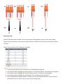
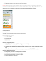
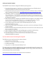
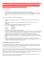
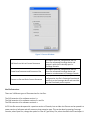
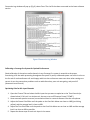
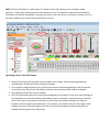
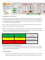
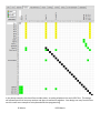
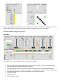
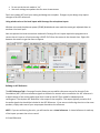
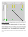
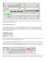
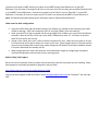
Converge Pro Field Survival Guide
Initial Connections
The Converge Pro system has a proprietary bus connection that allows the units to Transmit and Receive audio
and control data using a CAT5 cable with an RJ45 connector. This is a link in to link out configuration:
The Converge Pro system also utilizes Balanced Audio phoenix block I/O’s to maximize space. These are color
coded for your convenience:
Orange – Mic/Line Inputs
Green – Line Inputs
Black – Line Outputs
Balanced audio is a method of interconnecting audio equipment using balanced lines. This type of connection
is very important because it allows for the use of long cables while reducing susceptibility to external noise.
Balanced signal means better, stronger and cleaner signal between devices; it has nothing to do with left/right
stereo balance. You can tell if your device has balanced outputs or inputs if it features XLR connectors or TRS
connectors (tip-ring-sleeve) which are designed for a 3 conductor cable. If you are unable to provide a
balanced connection and will be wiring balanced to unbalanced please refer to the following Wiring Diagram:
Device ID’s (DID)
Device IDs provide unique identifiers for all units that are linked together using the E-bus. After making
Expansion Bus connections, you must set a unique Device ID number for all units of the same Device Type on
the E-bus.
Device Types and Device IDs by model are as follows:
1.
2.
3.
4.
5.
Press the Select button on the front panel. The CONVERGE Menu appears.
Use the Menu Dial to highlight the Settings menu. Press the Select button. The Settings menu appears.
Use the Menu Dial to highlight DID. Press the Select button. The Device ID menu appears.
Use the Menu Dial to highlight the desired value. Press the Select button to select it.
The Change DID Menu prompt appears. Choose Yes to set the selected DID value, or No to return to
the Device ID menu. Press Esc until to return to the Settings menu.
6. Repeat this process for each device on the E-bus network.
Caution: If you have built your site file offline and you are pushing a site file to the stack you will need to
match the Device ID of the software units to match the hardware units, or you will get extra units when you
connect and push the document to the units. Be sure everything matches before you push!
Installing Software
Converge Pro Console software minimum system requirements:
Supported Operating Systems
• Windows XP (SP3)
• Windows Vista
• Windows 7
• Windows 8
Minimum System Requirements
• AMD 600 MHz class processor (1 GHz or higher recommended)
• 1GB RAM Minimum (or higher recommended)
• 300MB hard disk space minimum (Additional space is required to store the site files and other project
files)
• USB or Ethernet Network Interface to connect your computer with CONVERGE Pro product
Minimum Software Requirements
• Administrator permission to install and run the software
• Java Runtime Environment version 6.0 or higher
• Microsoft Internet Explorer version 4.0 or higher
• Adobe Flash version 9.0 or higher
INSTALLING CONVERGE CONSOLE
The CONVERGE Console software is designed for Windows operating systems.
1. Ensure that all other programs or applications are closed and disconnect any USB cables from all
CONVERGE/CONVERGE Pro devices (you will reconnect them later).
2. Download and Install the latest version of Converge Console from our Resource Library > Professional
Audio > Downloads and Release Notes: http://www.clearone.com/resources#professional_audio
3. In Windows 7 and later, It is recommended that you run the SETUP program with a RIGHT CLICK to
“Run as Administrator.” The CONVERGE Console Setup Wizard appears. Press the Next button and
navigate through the License Agreement and Information screens that appear and follow the prompts
to complete the installation.
4. When Console installation is complete, the CONVERGE Console icon appears on your desktop. You can
now start Console over IP by double-clicking the icon, or through the All Programs > ClearOne
Communications > CONVERGE Console program group in the Windows Start menu.
5. To use a USB connection with Console, connect USB cables between the PC and the
CONVERGE/CONVERGE Pro device.
6. When the Found New Hardware Wizard appears, select the No, not this time radio button. Click Next
to begin installation.
7. Select the Install the software automatically radio button in the second screen of the wizard, then click
Next to proceed with installation.
8. When the Windows unsigned driver warning dialog appears, proceed to install the drivers.
9. When the USB driver installation is complete, click Finish to close the wizard.
10. If you will be using IP to run Console, connect Ethernet cables between your LAN and
CONVERGE/CONVERGE Pro device(s).
If you are unable to connect to the Converge Pro using USB:
The USB driver may not install correctly for a number of reasons:
• Restricted driver Installation policy
• Windows or 3rd Party security software and settings
• No Administrator Rights
• Using version 2.x or older Console with Windows 7 or 8
TIP: Bring a small router with DHCP capability with you when you work with Converge Pro systems in the
field. This will allow you to connect reliably in any situation. If you can’t bring a router or do not have one,
use the workaround in the next section below.
This freeware utility works with 64 bit Vista and later and can be found here:
http://sourceforge.net/projects/dhcp-dns-server/
You will need to make sure you are NOT connected to a network when running this utility. For this purpose, It
is ONLY to be used with a PC directly and exclusively connected to the LAN or PC port of the Converge Pro.
This software should be uninstalled after using or else you can cause problems when connecting to other
networks because your computer will still be acting as a DHCP server.
Installation instructions:
1. Download and install the software by clicking on the installation package EXE file.
2. The final screen on the installer package will ask you if you want to “Run Program” and “Install As
Windows Service” You DO NOT want to do this, make sure the checkbox is UNCHECKED. Then click
Next.
How to run the utility and connect to the Converge Pro:
1. You will first need to set your LAN port to the correct IP address. Open your Network Connections
folder.
2. Right click the LAN connection you will be using to connect with the Converge Pro and select
Properties.
3. Scroll down to TCP/IP Configuration and right click, then choose properties.
4. Select “Use the following IP” and use the following settings:
IP:
192.168.0.1
Subnet:
255.255.255.0
Gateway:
192.168.0.1
5. Select OK to close the window and save your settings.
6. Click Start, then open the folder called Dual Server, then click Run Stand Alone. This will start the DHCP
server utility (It looks like a DOS window with a black background). Connect your Ethernet cable (You
can use a crossover or patch cable) to the LAN or PC port on the back of the Converge Pro.
7. Watch the front panel of the Converge Pro. The IP address should change from 0.0.0.0 to a new IP
address. Close the DHCP utility window. You are now ready to connect to the unit with Console using
TCP/IP.
8. If you need to disable the Dual Server DHCP service from starting and running when you reboot
windows, click START and enter MSCONFIG in the run window. Hit enter and go to SERVICES. Find the
Dual-Server DHCP service and uncheck the box next to it.
Working With Converge Manager and Firmware
Converge Manager allows the user to choose which version of Converge Console they would like to run that
corresponds with the particular version of firmware they have on their Converge device. Site file corruption
can occur when mismatched software/firmware versions are used.
Each version of software matches the firmware by matching the first number. Check the firmware version on
the front panel (See Figure 1), and select the appropriate software version (See Figure 2). This can be done by
double clicking the selected software version in Converge Manager. If there are multiple Converge devices in
a stack make sure they are all on the same firmware version or errors can occur.
CAUTION: Use the correct version of software to connect and edit site files for the firmware level of the
hardware or file corruption and loss of data will occur.
Figure 1 Front Panel LCD
Figure 2 Converge Manager
USB Device not registered error on launch
If running version 1, 2 or 3 Console for the first time, you will get an USB device driver error when trying to
launch Console. To fix this, simply ACTIVATE all versions listed in Converge Manager. Highlight the version in
the list, then left click Activate Selected Version at the bottom. The error will go away.
Firmware Update
When updating the firmware first connect to the matching version of firmware on the Converge device. Make
sure you connect with good site data and unit data (See Figure 5), and save the site file. When updating the
firmware the site file on the Converge device will be wiped. The saved site file will need to be pushed to the
Converge device after the firmware update is complete.
Figure 3 Connection Bar
Firmware Loader Screen
When connecting to a Converge device that is on an older firmware version than the software version this
screen will automatically pop up. This can also occur when Converge devices in a stack have mismatching
firmware. Make sure that all firmware versions match and the active software version is correct.
Figure 4 Firmware Loader Screen
CAUTION: If you see this screen unexpectedly when you connect to a Converge Pro, STOP and close the
software. Use the correct version of software for the firmware you are connecting to.
Connecting to Converge Device
When the correct software version has been selected open Converge Console. Open up the Connect window
(See Figure 7). Connect either through the IP Connection by typing the IP address of Converge device or by
connection through USB. (Note: Firmware updates should always be done through USB connection.) For a
brief description on the Pull, Create, and Push options see below:
Figure 5 Connect Window
Pull Data from Unit to Current Document
Create New Document and Connect to Site
Connect to Site and Push Current Document
This option pulls the configuration site file
from the connected Converge device and
merges it with site file already open in
Converge Console.
This option pulls the configuration site file
from the connected Converge device and
creates a new document in Converge Console.
This option takes the already open
configuration site file in Converge Console and
pushes it to the Converge device and overrides
any site file already on the system.
Site File Extensions
There are 3 different types of file extensions for site files:
The CVG extension is for software version 1.x
The CNV extension is for software versions 2.x and 3.x
The CPD extension is for software version 4.x
A CPD site file cannot be opened in a previous version of Console, but an older site file one can be opened in a
newer version of software and will convert to that extension type. This can be done by opening Converge
Console, select Open Site, change the option for Files of Type to Any File, select the older site file and open. A
Conversion Log window will pop up (Fig. 6) select Close. The site file has been converted to the latest software
version.
Figure 6 Conversion Log Window
Calibrating a Converge Pro System for Optimal Performance
Good calibration of the various audio channels in any Converge Pro system is essential to the proper
functioning of all the audio processing throughout the system. A poorly calibrated system can result in echo on
the far end of a teleconference call and choppy audio into the conference room even when other settings are
correct. It can also cause other problems such as audio distortion, poor mic auto gating, and poor ALC
(Automatic Level Control.)
Optimizing Gain for Mic Input Channels
1. Open the Channel Tab and select the Mic Input that you want to optimize on the Tree View tab (as
shown below). If this mic is a wireless mic, be sure to turn off Phantom Power (“PPWR”).
2. Have someone speak at a normal, conversational level at a normal distance from the microphone.
3. Adjust the Coarse Gain Slider until the peaks on the Post Gain Meter are close to +6dB (just hitting
yellow), and the average level is close to 0dB.
4. Adjust the Fine Gain Slider until the peaks on the Post Gain Meter are as close to +6dB and the average
level is as close to 0dB as possible.
5. Repeat the above steps for each mic input in the venue.
NOTE: The Post Gain Meter is a peak meter. If it peaks into the red, clipping occurs resulting in audio
distortion. If the meter remains green the level may be too low. This approach to gain structure should be
followed on all channels throughout a Converge Pro system. Also note that on mic inputs it is better to err on
the side of audio that is a little low than audio that is too hot.
Optimizing Gain for Telco RX Channels
1. Optimize Telco RX inputs using the same procedure as mic inputs, with the following additional
considerations. (Please refer to the screen shot below.)
2. On a properly configured phone line, the Recv Input meter should show good levels. But if the levels
are too low, put a check in the “Recv Boost” check box and increase the Recv Boost as needed.
3. Then adjust the Post Gain meter as needed.
4. The Telco RX should maintain this same level throughout the Converge Pro site up to and including the
Line Output(s) to an external amplifier and speaker system. In particular, avoid lowering the Telco RX
levels at the input, at crosspoints, on busses or at the Line Outs and then turning up an external
amplifier to achieve good room audio levels. This, by itself, can cause far end echo, even when other
settings are correct. Instead, keep the Telco RX at Unity Gain and adjust the external amplifier as
needed to achieve good room audio levels.
Optimizing Gain for Telco TX Channels
The same principles of gain structure apply to the Telco TX channel. When someone talks on a microphone in
this Converge Pro system, the Telco TX Post Gain Meter should show the same levels as recommended for the
mic inputs. However, if this results in audio that is too low or too high as heard by a far end caller, adjustments
to the Telco TX gain should be applied as needed.
TIP: Turn up the Telco TX gain rather than turn up the mic gain for better transmit levels. It’s not unusual to
see telco TX turned up to 8 db or so for most phone systems.
NOTE: For this testing use a standard telephone handset on the far end because levels can be unpredictable
from speaker phones, cell phones, and amplified headsets. You can also use the System Test within the Debug
Console menu under the SERVICES tab to verify your analog phone signal:
> 24 V DC
> 20 mA
6 - 24 V DC
15 - 20 mA
< 6 V DC
< 15 mA
Levels at or above these
values should provide optimal
telco performance
At these levels you may
experience intermittent dial
tone or poor performance
Levels below these thresholds
are not supported
Optimizing Gain for Line Input and Output Channels
If the same principles of Unity Gain have been applied to all inputs, crosspoints, and Process or Fader Busses,
then the Line Output channels should already show Unity Gain. However, it is recommended that the levels on
Output Level meter be checked to verify this.
Further Considerations.
1. Simplicity. Avoid complex gain structures. For example, avoid boosting the gain of the Telco RX audio at
one point along its audio path, then dropping it as another point, and boosting it again at a later point.
2.
3.
4.
5.
Also avoid unnecessarily complex audio routing, such as routing an audio signal through multiple
busses or back and forth across multiple Converge Pro units.
Unity Gain. It is always best to set all inputs to Unity Gain and maintain that same gain level through
the Converge Pro system, unless attenuation is required for voice lift or to adjust levels to and from
attached audio devices.
When mics are routed to local speakers for sound reinforcement, this audio will typically need to be
reduced (attenuated) at crosspoints or on a process/fader channel to prevent local feedback. Care
should be taken to keep this routing separate from the routing of mics to the far end of a
teleconference.
When audio is routed from a Converge Pro Line Output to a Video Conferencing system input, the Line
Output gain will need to be adjusted according to the requirements of the input on the Video
Conferencing system. Adapting a Converge Pro line level output to a video codec mic input may
require an external line to mic level adapter.
User control of room audio levels should be done within the Converge Pro system. If the volume is
controlled at an external amplifier or other external device, volumes changes are likely to cause far end
echo, at least temporarily.
Basic Routing For a typical single room using VOIP, analog telephone, video conferencing, and mild voice
reinforcement.
For efficient and error free configuration, begin by clearing the matrix. Next, label
the inputs and
outputs you plan to use. For best results, use your room wiring diagram to plan the input and output channels
ahead of time. Always try to keep all amp outputs on a single unit to simplify AEC and control logic. Once all
calibrations are complete, begin routing your inputs and outputs using cross points in the matrix. Inputs are
on the left, audio flows in from the left and goes out the top. Audio routed to processes and faders goes out
at the top right and comes in again at the bottom left corner. Left clicks cycle available cross points; right
clicks give you extra GUI options. Black boxes can’t be routed.
When connecting multiple Converge Pro systems together, the expansion bus is used to route audio internally
over the bus to and from other units. External connections should not be used. In this example, mics from the
8i are routed out to the O bus from the 8i and come into the 880T from the O bus. The mics are then routed
through a control process and sent to multiple outputs, including to the VH20 through the S bus. Bus S then
comes in the VH20 matrix and goes out the VOIP TX channel.
Routing for a typical 880T, 8i, and VH20 installation in a medium sized conference room.
880T Matrix
In the above example, the site will use a video codec, an analog telephone line and a VOIP line. This design
will allow all parties to hear one another and share a conference together. Your design can vary from this but
use this route as an example of a simple and effective programming.
8i Matrix
VH20 Matrix
Note: In this example all microphones are being routed to the amp for reinforcement. If your design does not
call for reinforcement, simply omit the route to and from Process D in the matrix of the 880T.
Recommended Mic settings for basic rooms
Wired Mics
(For wireless mics, turn off PPWR and lower coarse gain as needed)
•
•
•
•
•
•
•
•
Coarse and fine gain should be calibrated so that human voice peaks at 0db on the post gain meter.
Noise Cancellation should be enabled and set to 6db.
Filter settings should not be used unless necessary to shape the audio. Avoid complicated filters.
Avoid AGC and ALC processes unless necessary for capturing variable audio levels from a moving talker.
Good gating parameters can solve many problems, start with these settings:
Gate Ratio to 18db
Hold Time 0.3 sec
Off Attenuation to 18db
•
•
Do not set the last mic mode to “on”
Use stock settings everywhere else for most circumstances.
Don’t worry about AEC until your routing and design are complete. Changes to your design may require
changes to the AEC references.
Using wireless mics or line level inputs with Converge Pro microphone inputs
Wireless mics need the phantom power (PPWR) disabled and most need the course gain adjusted down to
emulate a line level input.
Non-microphone line level connections made with Converge Pro mic inputs require the programmer to
convert the mic input to a line input using a RIGHT CLICK from the mouse in the channel view. Right click
between the meters to get the menu to appear.
Building an AEC Reference
The AEC Reference Tab in Converge Console allows you to establish reference sources for Acoustic Echo
Cancellation (AEC.) AEC uses reference signals as the basis for acoustic echo cancellation. An AEC reference is
a digital sample of the receive audio signal that is used by the AEC filter model for adaptation and
convergence. The simplest AEC Reference is the output to the amplifier. This output typically contains all of
the audio signals that should be included in the AEC Reference. If you are not reinforcing the mics to the room
speakers, simply select one of your amp output channels as the reference.
NOTE: If you are reinforcing the mics, you will need to use a virtual reference. A virtual reference is made up
of the inputs you want the mics to cancel.
A Virtual Reference
In this example, the virtual reference points come from the last process points the far side audio goes through
in the matrix. This allows the AEC to track gain changes made by volume controls. It is very important that
the gain at these points be at 0db. If the AEC samples audio at points that are artificially turned down in the
matrix but are amplified loudly in the room, chopping or echo will be heard by the conference participants.
Do not include microphone crosspoints in the virtual reference column, this will cause the mic to cancel its
own audio.
Remember, the idea behind AEC is that you want to provide the AEC a sample point of the audio you want to
cancel that is at the same gain and EQ as what is coming out of the amp into the room. Lowering your gains in
the Clearone system and hopping up your external amp to make it “sound right” is a great way to create
choppy audio and echo for the far side. Calibrate your amp down to conform to a 0 db output from the
Clearone and you will avoid problems.
Volume control points need to be calibrated to 0 db, not in the -10 to -15 db range. See below for what this
looks like.
Once you have calibrated the amp and the control point for a 0 db signal, you can adjust the volume up or
down at that point without problems.
Expansion Bus Reference Sources
To allow mics on other units to “see” an AEC reference created on your “main” Converge pro, you need to
create an Expansion Bus Reference. On the AEC REFERENCE tab of the “main” unit, in the top right corner,
define the Ebus Reference of your choice to share the reference. In this case, the UNIT is the 880T and the
OUTPUT is Virtual Reference 1.
All other mics across the other units should be set to use Ebus Ref 1 to share this reference from your “main”
unit. All crosspoints and channels should remain at 0 db.
Use the Expansion Reference Definitions (1-8) section of the screen to define an Expansion Bus Reference to
reference a channel or Virtual Reference that is on a different Converge unit in the site. For each expansion
reference definition, select the Unit and the Output you want to use as a reference using the drop-down lists.
Use Expansion Bus References for mic inputs on other Converge Pro units so that the inputs on these units can
reference a channel or virtual reference on one main Converge Pro unit. Consider, for example, this scenario:
you have as site with an 880T with the mic inputs on this 880T using Virtual Reference 1 as their AEC
Reference. You also have 3 Converge Pro 8i units on this same site. You can then you can define Expansion Ref
1 as the 880T, Virtual Reference 1, and the mics inputs on all of the 8i’s can use “Ebus Ref 1” as their AEC
Reference. In this way all of the mic inputs on all 3 of the 8i’s can reference the 880T’s Virtual Reference 1.
Note: The Beamforming Microphone Array will always need an Expansion Bus Reference.
Other notes for basic configuration
•
•
•
•
Leave telco RX at 0 db and use default settings, but calibrate it if needed so that incoming calls meter
at 0db on average. VOIP lines sometimes come in very high (10db +) from the network.
Raise your telco TX as high as needed, but do not go higher than 12 db or so or you will clip and distort
the audio. Most of the time I finish up a room with a 6 db boost to telco TX. It is better to raise the
telco TX than to turn the mics up.
Gating is your friend, don’t turn it off or use blue crosspoints for mics. Make sure mics gate on for you
in the room and not for the far side or for noises in the room. Raise the gate ratios or increase the Non
Linear Process settings (Mic channel view, under little green AEC button) to eliminate stubborn echoes
if all other calibrations are already at 0 db.
When using presets for multi-room divisions and combinations, begin by configuring a completely
combined configuration and save that as your starting preset.
Before Calling Tech Support
Be sure to visit the resource library to obtain manuals and tech notes for the system you are installing. Many
basic questions are already answered for beginners and pros alike.
http://www.clearone.com/resources#professional_audio
You can call tech support at 800-283-5936 or email [email protected] M-F between 7 am and 6 pm
MST.