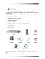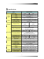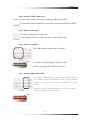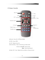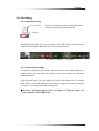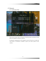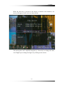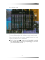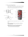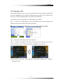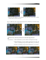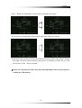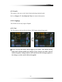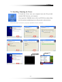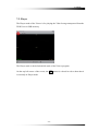
1
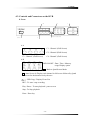
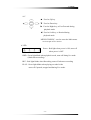
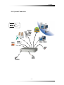
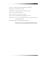
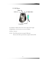
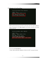
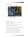
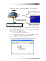
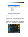
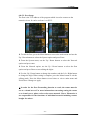
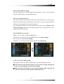
Instruction Manual Stand-Alone 4 Channel Digital Video Recorder Model CDR4450 Copyright © 2008 Clover Electronics U.S.A. All Rights Reserved. Contents Contents 1. Unpacking 6 About This Unit 7 2. Features 8 3. Specifications 9 4. Installation 10 4-1. 4-2. 4-3. 4-4. What to do before Installation Installation Check List Controls and Connectors on the DVR System Connection 4-4-1. 4-4-2. 4-4-3. 4-4-4. 4-4-5. 4-4-6. 4-4-7. Camera Connection Video Output Connection / VGA Connection Audio Connection Network Cable Connection Mouse Connection Sensor Connection Alarm Output Connection 4-5. Step by Step Installation 16 16 16 17 17 17 17 18 5. How to Operate 5-1. 5-2. 5-3. 5-4. 5-5. 10 11 12 15 19 General Operation Remote Controller PS/2 Mouse Running for the First Time Live 19 20 22 23 25 5-5-1. Quad Split Screen Display 5-5-2. Full Screen Display 5-5-3. Auto Sequence Display 25 26 27 -1- Contents 5-5-4. PAN / TILT & ZOOM 28 5-5-4-1. How to Connect PAN / TILT Device 28 5-5-4-2. How to use PAN / TILT 29 5-5-4-3. How to use ZOOM / FOCUS 29 5-5-5. Toggle OSD ON/ OFF 5-6. Recording 30 31 5-6-1. Manual Recording 5-6-2. Automatic Recording 31 31 5-7. Playback 32 5-7-1. Set Playback Time 5-7-2. Search by Event 5-7-3. How to Search through Playback 5-8. Copying to USB 32 35 36 37 6. Setup 40 6-1. Setup Menu 6-2. Camera Setup 40 41 6-2-1. Channel 6-2-2. Display 6-2-3. Camera Color Option 42 43 45 6-3. Record Setup 6-3-1. 6-3-2. 6-3-3. 6-3-4. 46 Record Speed Record Quality Hold Time Record Schedule 47 49 50 51 6-4. Sensor 53 6-4-1. Relay Output 6-4-2. Sensor Setup 55 6-5. Motion Detection 57 6-5-1. 6-5-2. 6-5-3. 6-5-4. 54 Channel Selection Sensitivity Selection Relay Output Setup Motion Area Setup 58 59 60 61 6-5-4-1. Area setup using Direction keys 62 6-5-4-2. Area setup using the Mouse 63 -2- Contents 6-6. Screen Setup 64 6-6-1. Border Setup 6-6-2. Video Adjustment 6-6-3. Sequence Setup 65 65 65 6-7. Audio Setup 66 6-7-1. Audio Record Setup 6-7-2. Mute Setup 6-7-3. Input / Output Volume Setup 6-8. System Setup 66 67 67 68 6-8-1. Hard Disk Setup 68 6-8-1-1. Overwrite Option 69 6-8-1-2. Format HDD 69 6-8-1-3. Hard Disk Drive Information 71 6-8-2. Password Change 6-8-3. Time Set 72 76 6-8-3-1. Time Zone Setup 76 6-8-3-2. Time Setup 77 6-8-3-3. Daylight Saving Option 78 6-8-3-4. Synchronize with NTP Server 78 6-8-4. Event List 6-8-5. Network Option . 78 79 6-8-5-1. Network Enable Option 79 6-8-5-2. Local IP Setup 80 6-8-5-3. Port Setup 83 6-8-5-4. MAC Address Setup 84 6-8-5-5. Network Password 84 6-8-5-6. DDNS Server Setup 84 6-8-5-7. Network Video Quality 84 6-8-6. RS-485 Setup 6-8-7. PAN / TILT Device Setup 85 86 6-8-7-1. Channel / ID Setup 86 6-8-7-2. Model Option 86 6-8-7-3. PAN / TILT Test 86 6-8-8. Firmware Upgrade 87 6-9. Search 6-10. Language 89 89 -3- Contents 6-11. Exit 89 7. Viewer 90 7-1. Installing / Running the Viewer 7-2. Player 7-2-1. 7-2-2. 7-2-3. 7-2-4. 7-2-5. Menu Icons How to Open a Video File How to Save as AVI file How to Capture a Screen 7-3. Network Viewer 91 92 93 94 95 96 98 99 7-3-1. How to Connect to the DVR 7-3-2. Menu 7-3-3. Icons Warranty Information / How to obtain Factory Service -4- 99 102 103 104 Contents About this manual This is the instruction manual for the Stand-Alone type DVR, CDR4450. This manual describes how to install and operate the CDR4450 and provides information regarding specifications and features of this product. Please be sure to read this manual and follow the instructions when installing the CDR4450. If you have any questions or problems installing, please contact Clover Electronics at 877-327-5000. -5- Contents 1. Unpacking When unpacking the DVR Unit, please be cautious not to drop, throw or hit with force. This may cause damage to the product that could lead to malfunctions. Before Installation please check if the following objects are included. Stand-Alone DVR unit Remote Controller & battery Instruction manual NetViewer CD Adapter and screws (usage for installing HDD) RJ-45 Cable PS/2 Mouse DVR Adapter Remote Manual Screws CD-ROM Battery RJ-45 Cable PS/2 Mouse Ú If any of the above items are missing please contact Clover Electronics -6- Contents About This Unit You have just purchased a state-of-the-art 4 CH Stand Alone DVR with network connection. The most interesting feature of this system is the USB Firmware updating option, which enables software upgrading and software management to be done at home with a computer and a USB drive, instead of sending the DVR. To enhance the user friendliness of this DVR system, the user can operate with both the remote controller and a PS2 mouse. We hope you have a great experience with our CDR4450. Thank you. -7- Contents 2. Features Triplex (Record / Playback / Live) Real Time Full, Quad and Auto sequence Display mode High Quality, Low Cost and Full Option System Stand Alone Type (Non-PC, Non-OS) Programming MENU in OSD (On Screen Display) Built-in Time / Date Generator Event list of 127 Motion / Alarm detection and Schedule recording Quick Search : Date & Time / Event Hard Disk Drive Overwrite RS-485 Interface for PT Camera control (Option) Multi-user network monitoring and remote DVR controlling (up to 2 users) Copy and Firmware Update by USB VGA connection MJPEG Compression Remote Control -8- Contents 3. Specifications Items Specifications System Type Video Signal Audio Display NTSC Input 1Vp-p 75Ohm, Input BNC ¯ 8 VGA VGA Output ¯ 1 Output 1Vp-p 75Ohm, Input BNC ¯ 2 Input / Output 2 ¯ RCA (1CH Input, 1CH Output) Recording Mode Mono PCM Display Frame 60 Field per sec (each) 50 Field per sec (each) Display Resolution 640 ¯ 448 640 ¯ 544 Real-Time full triplex M-JPEG codec core Video Compression Video Resolution Recording Network Playback Alarm Control PAL 640¯ 224 640¯ 272 Continuous, Event (Motion & Alarm detection) Recording Method Recording Field 60 Field per sec 50 Field per sec Image File Size 3 ~ 25KB 4 ~ 27KB Resolution 640 ¯ 224, 320 ¯ 112 Feature Real time Transmit, Remote Control Connection TCP/IP, UDP, DHCP, PPPoE Playback Mode Playback Screen Mode Search Live, Playback Search by Date / Time, Event List External Alarm Input Alarm Input : Terminal Block 8 Alarm Output Relay Out : Terminal Block 1 Full, Quad, 9 split mode -9- Contents 4. Installation 4-1. What to do before Installation Make sure all the required hardware is available. - Stand-alone DVR unit (HDD installed) - 4 Cameras (including power for each camera unit) - CCTV or VGA monitor (or TV set) - Network cable (for connecting to network) Connect the cameras to the DVR unit and the DVR unit to the monitor (video output device) Perform HDD format at the first screen to proceed Confirm live video is displayed on the monitor before proceeding to the next step. Select the Setup Menu and set the current date and time Set values for required options such as motion detection, etc. Be sure to setup the network on the DVR before utilizing network connection. - 10 - Contents 4-2. Installation Check List Are the cameras installed at the right position? Are the camera cables connected to the inputs? Is the audio cable connected to the input? Is the system set on a stable location? Is the placement of the system clear from any elements such as water, excess dust, direct sunlight, magnetic field, etc… Is the system located away from temperatures beyond 32ºF~122ºF Is the location of the DVR unit away from the reach of children? Are the batteries inserted correctly in the remote controller? Is the mouse compatible with PS/2? Is the video output cable connected to the correct jack? Are all components (cameras, DVR) connected to the correct power supply? - 11 - Contents 4-3. Controls and Connectors on the DVR Front B LED C Remote controller sensor USB Port A ÚA C1 : Channel 1(Full Screen) C2 : Channel 2(Full Screen) C3 : Channel 3(Full Screen) C4 : Channel 3(Full Screen) ÚB OSD ON/OFF : Date / Time / Memory usage Display option : Back to Quad Screen Mode : Auto Screen B Display each channel in full screen followed by Quad screen for the duration set by the user. : USB Copy / Display Event List REC : To start / stop recording Play / Pause : To start playback / pause screen Stop : To Stop playback Enter : Enter key - 12 - Contents ÚC S : Used as Up key T : Used as Down key X : Used as Right key, or Fast Forward during playback mode W : Used as Left key, or Rewind during playback mode MENU/STOP/ESC : used to enter the Main menu or to escape to live screen Ú LED Power : Red light when power is ON, turns off when power is OFF HDD : Green light blinks when playback mode, turns off during live mode (blinks when recording) REC : Red light blinks when Recording, turns off when not recording PLAY : Green light blinks when playing recorded video turns off if paused, stopped and during Live mode. - 13 - Contents Rear Audio connection port Main Power switch Network A connection port VGA Port PS/2 Mouse port DC 12V adaptor port Video output device port Camera Input port ÚA Alarm output Alarm Input RS485 Grounding Alarm Input : The user can connect to ports 1 ~ 4. Grounding : All alarm input must be connected to this grounding port. Alarm Output : Connect one line to “COM” and the other to either Normal Open(N.O) or Normal Close(N.C) according to system setup - 14 - Contents 4-4. System Connection Input Output Input / output Network - 15 - Contents 4-4-1. Camera Connection Connect the cameras to the Video Input (BNC Connector) on the back of the unit as shown. On this unit, the user can connect up to 4 Cameras. 4-4-2. Video Output Connection / VGA Connection Connect the composite monitor to any one of the BNC ports. This unit can support up to two composite monitors at the same time. The video output to the two monitors will be the same. Connect the VGA Monitor’s connector to the “DSUB 15 Pin Connector” on the rear of the unit. The Video Output from the VGA port has the same content as the output from the BNC port, but the quality of the video stream will be better. 4-4-3. Audio Connection Connect the speaker and audio input line to this port. This unit can only support one audio input. - 16 - Contents 4-4-4. Network Cable Connection Our Network Cable Connector is designed for RJ45 type cables. Connect the Network cable here to utilize the network function of the DVR 4-4-5. Mouse Connection This port is designed for PS/2 devices. Connect the mouse here to utilize the device in the DVR system 4-4-6. Sensor Connection The DVR unit has 4 Input ports for Sensors. . trigger To connect, press the trigger to open the socket Ú Note : the trigger may be difficult to press. 4-4-7. Alarm Output Connection To connect Alarm Output, Connect one end of the cable to the Common socket (COM) and the other to either Normal Open(N.O) or Normal Close (N.C) depending on system setup. Like the Sensor Connection (Refer to 4-3-6), the trigger must be pushed to insert the cable. trigger - 17 - Contents 4-5. Step By Step Installation Set Cameras in position Set Audio Input device in position Set Sensor device in position Set DVR unit in position. Ú Note : The DVR unit must use the 12V adaptor that comes with the set. Usage of other adaptors may cause malfunction. Connect DVR unit with the Cameras, Audio Input device and Sensors. Connect a VGA monitor or (and) a composite monitor to the DVR unit. Check if the Video Output and Audio Output are clear. If there is a problem after correct setup, please contact Clover Electronics. If you wish, you may connect the DVR unit with a PS/2 mouse. Connect the DVR unit to the network using the standard RJ45 type network cable. Check the remote controller for correct installation of batteries. Contact Clover Electronics for Latest Firmware update. You are good to go!!! (Check 4-4. System Connection) - 18 - Contents 5. How to Operate 5-1. General Operation You can operate the functions of the system by using the buttons located at the front panel of the DVR unit, as well as the remote controller and a PS/2 mouse. The system status is indicated by either the LED lights located near the center of the front panel, or the monitor. This system is protected from pressing the buttons by accident, but be careful when using the “Hard Disk Setup” option, for this may lead to data loss, and the “Password Change” option. (If you forget your password, please contact Clover Electronics for help) - 19 - Contents 5-2. Remote Controller Record Play Enter USB OSD Menu / Stop LIST Direction keys 9 Screen PAN/TILT Quad Screen Auto Sequencing Number keys Record : Select ON / OFF Record Mode USB : Copy to USB LIST : Display Event List Direction Keys : Work as direction keys in Menu mode In Play mode S, T : frame by frame W, X : Fast forward, Rewind Menu / ESC / Stop : Display On Screen Menu or Escape to Screen - 20 - Contents 9 Screen : 9 Split Screen mode(Not supported in 4 CH DVR) Quad Screen : Quad Split Screen mode Number keys : Used to select camera in Full Screen mode Play : Used to select Playback mode Enter : Used to select a certain menu / option OSD : Used to select OSD(On Screen Display) ON / OFF PAN/TILT : Used to select PAN/TILT option from Camera direction to Camera Zoom & Focus Auto Sequencing : Used to select Auto Screen Mode. The Screen will switch automatically showing all channels in Full Screen mode, then in Quad Split mode during the set time. - 21 - Contents 5-3. PS/2 Mouse Wheel Right button Left button PS/2 Connection Left Button : Double click to select screen, single click to toggle. Right Button : click for menu, or to use as exit button. Wheel : Not used PS/2 : This DVR system does not support USB mouse. Please use the PS/2 type mouse that is supplied with the DVR. - 22 - Contents 5-4. Running for the First Time When you turn on the power for the very first time, the screen will be shown as above. You must press the Enter button on the Remote controller or the Front Panel to proceed. If you press the Enter Button, “Disk0 : PRESS [ENTER] FORMAT, [STOP] CANCEL” message will show. - 23 - Contents Press the Enter Button again to format the HDD and make it ready for use If HDD Format is successful the first screen that comes out will be as shown above Ú If there is an error with the camera or if there is no camera connected to the port, a blue screen will appear as shown below. - 24 - Contents 5-5. Display Screens Camera Number Motion Detect Icon Camera Number Recording Icon Lock Icon HDD Use Network Sensor Motion Detect Date / Time Alarm Trigger Record Schedule 5-5-1. Quad Split Screen Display The Quad Split Screen Display is the default display of this DVR unit. The 4 Cameras are named as C1 ~ C4 If Motion Detection is set, the Motion Detect Icon will show if there is a motion, and will disappear if there is no motion The Recording Icon will show if Recording is in process, and disappear if not The Lock Icon will show if the DVR is set to Lock (Press the Left key (W) 5 times to trigger Lock, Right key (X) to trigger Unlock). The Alarm Icon will show if there is an event that triggers an alarm. In this case the Motion Detect option has triggered the alarm. The percentage at the bottom shows how much HDD has been used. - 25 - Contents 5-5-2. Full Screen Display Motion Detect Icon Camera Number Recording Icon PAN / TILT Icon Network Sensor Motion Detect HDD Use Date / Time Alarm Trigger During Full Screen Display mode the user can see the video from a certain camera in a larger scale. To view in Full Screen Display mode, Press the Camera number button on the Front panel, or on the remote controller. You can also select a screen by double clicking your mouse. From the Full Screen Display mode, you can adjust the PAN / TILT & ZOOM The PAN / TILT icon is shown above while the ZOOM icon is shown below. ZOOM Icon - 26 - Contents You can navigate through these options by using the Enter key. While utilizing the PAN / TILT option, use the direction keys on the Front Panel, or the remote controller. In ZOOM mode, the up and down keys(T, S) are used as zoom in and zoom out, the left and right keys(X, W) are used to adjust the focus of the camera. Ú For more information about PAN / TILT and ZOOM, please refer to the manual supplied with your camera. 5-5-3. Auto Sequence Display Auto Sequence Icon When Auto Sequence Display mode if toggled, the display screens will be displayed in sequence (Quad p C1 p C2 p C3 p C4 p Quad). The Auto Sequence Display will stop if the user presses a button on either the Front panel or the Remote Controller. Ú The OSD button will not stop the Auto Sequence Display, because the OSD is not programmed to toggle during Auto Sequence Display mode. - 27 - Contents Auto Sequence The time frame of the screen shown can be adjusted through the SCREEN option in the Menu. (Refer to Chapter 6-6-3. Sequence Setup) 5-5-4. PAN / TILT & ZOOM In this chapter, the user will be instructed on how to connect a PAN / TILT Camera and how to operate it through the DVR Unit. Ú Refer to Camera Specs / Manual for information 5-5-4-1. How to Connect PAN / TILT Device Connect the RS-485 lines to the rear terminal port of the DVR Unit After connecting the Camera to the RS-485 Port, Refer to chapter 6-8-6. RS-485 Setup and chapter 6-8-7. PAN / TILT Device setup for software configuration. - 28 - Contents 5-5-4-2. How to use PAN / TILT The PAN / TILT function can be used in Full Screen Mode only. When in Full Screen mode, press the button to enter PAN / TILT mode. When PAN / TILT Mode is initialized, the icon will show on the bottom of the screen. When shows on the screen, the Direction Keys on the Remote Controller and the Front Panel will work to move the camera. 5-5-4-3. How to use ZOOM / FOCUS The ZOOM / FOCUS of the camera can be altered by pressing the or the button button while in PAN / TILT Mode. When ZOOM / FOCUS Mode is initialized, the Icon will change into Icon. When shows on the bottom of the screen, the Up / Down buttons on the Remote Controller and Front Panel will work as Zoom In / Zoom out buttons, while the Left/ Right buttons will work as Focus buttons. - 29 - Contents 5-5-5. OSD ON / OFF By using the OSD button on either the Front Panel, or the Remote Controller, one can toggle the OSD (On Screen Display) ON and OFF. The user can select OSD ON & OFF during Full Screen Display mode and Quad Split Screen mode. Ú If there is a shift in Screen modes, the OSD will appear again. - 30 - Contents 5-6. Recording 5-6-1. Manual Recording Front Panel The user can manually start recording the video footage by pressing the buttons shown. Remote The Manual Recording will start recording only if the Sensor, Motion Detect and Record Schedule is not set. The icons are shown below. Sensor / Motion / Schedule 5-6-2. Automatic Recording To enable recoding when the Sensor / Motion Detector / Recording Schedule is triggered, the user must press the Record button after setting the functions mentioned above. If the Record button is pressed while any of the three functions are enabled, there will be no recorded data unless the sensor is triggered, motion is detected or if there is a recording schedule presently set. Ú For more information please refer to Chapter 6-3. Record Setup, 6-4. Sensor and 6-5. Motion Detection - 31 - Contents 5-7. Playback 5-7-1. Set Playback Time The screen as shown above will appear if the Play button on either the Front Panel or the Remote controller is pressed. To adjust the starting point of the playback, press the Enter key on either the Front Panel or the Remote Controller or place your mouse pointer on the numbers. - 32 - Contents When the enter key is pressed or the mouse is clicked on the numbers, red arrows will appear on the screen as shown below. The starting time can be adjusted using the Up / Down keys to change the value, Left / Right keys to change the digit or by clicking on the arrows. - 33 - Contents After setting the starting point, to Start Playback, exit the editing mode by pressing the Menu/Stop/ESC Button and then select the Search option and press the enter key or just click on Search with your mouse. Ú The video footage will not play unless you press Enter on the Search option - 34 - Contents 5-7-2. Search by Event The screen will show as above if the List button is pressed during Live mode. From the list as above, the user can search, using the Directions keys, for the event the user wishes to watch the playback from. Ú The Up / Down keys(S, T) are used to scroll through the list and the Left / Right keys(W, X) are used to go through the pages or you can use your mouse to choose your event. - 35 - Contents 5-7-3. How to Search Through Playback During Playback Mode, the buttons on both the Front Panel and the Remote Controller work differently from how it did during Live Mode. The functions of the buttons during Playback mode are as shown. Play / Pause Copy to USB Toggle OSD Play / Pause Toggle OSD Copy to USB USB copy ESC to Live Back Back to Playback Start time to mode Rewind Playback mode Fast Forward ESC to Live USB copy Start time mode Select Quad Fast Forward Rewind ESC to Live USB mode Split Screen USB copy Select Full Screen Channel copy End time Both Rewind and Fast Forward functions can be set to 3 different speeds. Ú The speed Rewind and Fast Forward functions are different from a typical VCR. Ú Please be careful not to press the menu button by mistake. This will Exit to Live mode, not Stop the Playback. There is another button with the Stop function. - 36 - Contents 5-8. Copying to USB This option enables the user to extract certain amount of video data from the DVR Unit to a USB Memory. By Utilizing a USB Memory instead of a CD / DVD allows the user to extract and transport the video data more efficiently. The steps to copy the video data to a USB memory is as shown. Step 1 : Format your USB Memory. (Insert USB Memory into your Computer and follow the steps below and click on Start to Format) Ú Caution : Formatting USB memory can cause unwanted loss of Data FAT32 Format Right Click Step 2 : Insert the USB Memory into the DVR Unit. Step 3 : Search the playback video data for the data you need and then click (or press Enter button on the remote controller) on Search as shown below. Press Enter to edit, Up / Down buttons to change the numbers, Left / Right to change the digit - 37 - Contents Press the Menu button to exit editing the time and date, Down button to select Search and press Enter to proceed. Step 4 : While the video is being played, Press the Up / Down key to select the range of data to be copied to the USB memory Ú Notice the size of the data will increase as the time range increases Known Errors : c When USB button is pressed without selecting the time range d When USB button is pressed without selecting the time range and if there is something wrong with the USB memory, or no memory e If there is something wrong with the USB memory, or no memory 1 2 3 - 38 - Contents Step 5 : When the USB button is pressed after setting the time range The process of reading the USB memory takes time. Please be patient. When the Enter button is pressed, the DVR will write the data to the memory. During this stage, the status will be shown by the increase of “Writing to USB” file size, and the decrease of the “Time to Remain” Ú Please note that this procedure may take time depending on the size and speed of reading the USB memory - 39 - Contents 6. Setup 6-1. Setup Menu The Setup Menu can be toggled by pressing the Menu Button from the Front Panel or the Remote Controller. The Menu provides options to the user to customize the DVR unit on how it operates. The menu is designed to be safe from unwanted operations executed by pressing the wrong buttons by mistake. But be aware that the Hard Disk Setup menu can lead to unwanted memory loss. Ú If you ever lose your password, please contact Clover Electronics - 40 - Contents 6-2. Camera Setup When the Menu Screen is toggled, the Camera is selected by default. Press the Enter button on either the Front Panel or the Remote Controller to enter the Camera option. Clicking on the option with your mouse can also be used. - 41 - Contents 6-2-1. Channel To enter the Camera Setup mode, select the Camera Setup option from the Main Menu and press Enter, or click on the option using your mouse. The Channel option is used to navigate through each camera in order to adjust the Camera Display option. The Channel can be changed using the Left / Right keys (W, X) or by clicking on the red arrows. When the Channel option is switched to a different camera, the screen on the back will show the image from that camera and automatically show the settings of the camera chosen by the user. - 42 - Contents 6-2-2. Display Press the Menu button to show the main menu From the main menu, select the Camera option and press Enter. To search though the menu, use the Up / Down buttons. From the Camera option, select the camera of which the options should apply to by using the Left / Right buttons while selecting the Channel option. From the Camera option, use the Up / Down arrows to select the Display option and use the Left / Right arrows to choose ON / OFF. After choosing the option, press the menu button to exit to main menu. - 43 - Contents From the main menu, press the Menu button to exit. Select the Exit & Save Changes option to exit and save changes. If the Display option was set to OFF the screen for the corresponding camera will turn black. Ú Even if the cameras are not connected (shown blue as above) will turn black if turned Off. - 44 - Contents 6-2-3. Camera Color Option The user can adjust the Camera Display just like adjusting any other video output such as monitors or TV’s. Use the Left / Right keys(W, X) to adjust the value, and Up / Down keys(S, T) to navigate through the options. - 45 - Contents 6-3. Record Setup The Record menu is for the user to customize the quality of the picture recorded, how long it is recorded and when it is recorded for automatic recording. - 46 - Contents 6-3-1. Record Speed To enter the Record Setup, Select the Record Setup option from the Main menu. The Record Speed option is to adjust how many fields each video footage should record per second. The more the fields, better the quality of the video stream. - 47 - Contents Ú Please note that the total Fields that could be used is 60. Allocate the fields used by each camera according to priority. The values can be changed using the Left / Right keys(W, X) on the Front Panel or the Remote Controller and by clicking on the red arrows with the PS/2 Mouse. Ú Please note that is a camera was turned OFF in the Camera Display option (refer to chapter 6-2-2. Display) the field for that certain camera will be set to 0. - 48 - Contents 6-3-2. Record Quality There are 3 options for Record Qualities (High, Normal, Low). Select the Recording Quality using the Left / Right buttons. - 49 - Contents 6-3-3. Hold Time The Hold Time option is used to set the time to record when an event is triggered by the sensors set by the user, or by Motion Detection. (For information on Motion Detection refer to Chapter 6-5 Motion Detection) To change the value, use the Left / Right buttons while selecting the Hold time option. - 50 - Contents 6-3-4. Record Schedule For Record Schedule setup, first enter the Record Setup option from the main menu by pressing the menu button Ö select the Record option using the Up / Down button and press enter. From the Record Setup option, select the Record Schedule option using the Up / Down button and press enter. From the Record Schedule option, one can select the time frame of when the DVR should record. Each cell represents 1H. Press the Enter button to toggle one cell, and press the Play button to toggle all cells. After setup, press the Menu button to exit to main menu. - 51 - Contents Exit & Save Changes to apply the Record Schedule. If the schedule is applied, a clock icon ( ) will appear at the bottom of the screen as shown. If the Record button is pressed while this Icon is present, the video will only be recorded during that time frame set by the user. Ú The Play key is used to toggle all sectors. This will affect all the sectors at the same time, and set the sectors to the same option. - 52 - Contents 6-4. Sensor The Sensor option of the menu is used to customize the alarm function of the DVR unit. Press Enter while selecting this option or click on the Sensor option to adjust. - 53 - Contents 6-4-1. Relay Output To enter the Sensor Setup mode, select the Sensor Setup option from the Main menu and press Enter. The Relay Output option, like the Hold Time option in the Record Menu, is used to set how long the alarm should be relayed for when the sensor is triggered. Ú The Sensors must be connected correctly to the terminal block at the rear panel of the DVR unit for the alarm to work. Be sure to connect all sensors to the Ground port as well as the Sensor Input ports. - 54 - Contents 6-4-2. Sensor Setup The Sensor (PIR: Passive Infrared) Setup is to set when the alarm should trigger. To enter the Sensor Setup, press menu to enter the main menu, select the Sensor option using the Up / Down button and press enter. In the Sensor Setup menu, the user should use the Up / Down button to select each Sensor and the Left / Right keys to change the value. After Setup is complete, press the Menu button twice and select Exit & Save Changes to apply the changes. When the Sensor is set, the icon will show at the bottom of the screen. If the Sensor is triggered the icon will show at the top right corner of the camera screen where the sensor is linked to. (In this case, the sensor linked to camera 3 is triggered) N.C : Normal Closed, meaning the trigger on the sensor is normally on closed and will trigger if the circuit is broken. Refer to image below. Alarm Sensor - 55 - Contents N.O : Normal Open, meaning the trigger on the sensor is normally on open and will trigger if the circuit is closed. Refer to image below. Alarm Sensor Disable : Means that this certain sensor port is not in use. Ú Be sure to connect all sensors to the GND(Ground) port. If any of the sensors is no connected to the GND port, the sensor will not function properly. Please check if the sensor set is the same as the alarm output. If the Sensor is set to NC and alarm connected to NO, the alarm will not function properly. - 56 - Contents 6-5. Motion Detection The Motion Detection Option is used when the user wishes to set the DVR to watch out for motion. To enter the Motion Detection option, press Enter while selecting the menu, or click on the Motion Detection option with your PS/2 mouse. - 57 - Contents 6-5-1. Channel Selection To enter the Motion Detection Setup, select the Motion Detection Setup option from the Main menu. The Channel Selection option enables the user to select a specific camera to set and enable motion detecting. When a specific camera is selected by searching through the Channel Selection using the Left / Right keys or by clicking on the red arrows with the mouse, the screen will show the video from the selected camera on Full Screen mode behind the menu. - 58 - Contents 6-5-2. Sensitivity Selection From this option the user can select the Sensitivity level from 1 ~ 4. The Red Square behind the menu area is a virtual simulation of how much motion must be present for the DVR to sense through motion detecting. Ú To see the Red square, there must be movement at the camera and the Sensitivity must not be set to OFF while in Motion Detection Setup. The Sensitivity of motion is determined by the motion within a certain number of cells. For example, if the Sensitivity is set to 1, then the Motion Detector will trigger if the DVR senses motion in one cell. Ú The cell will be further explained in Chapter 6-5-4. Motion Area Setup. - 59 - Contents 6-5-3. Relay Output Setup The Relay Output is the duration of time in seconds of the alarm output when motion is detected. The user can set this duration from a range of 5sec to 30sec to continuous. - 60 - Contents 6-5-4. Motion Area Setup To enter the Motion Area Setup mode, select the Motion Area option from the Motion Detection Setup. (Main menu Ö Motion Detection Ö Motion Area) When the Motion Area setup option is selected, the default Motion Detection area is set as shown. - 61 - Contents 6-5-4-1. Area Setup using Direction Keys To start setup the area of detection using the Direction Keys, press the Enter key to start and confirm area setup, the direction keys to adjust the size of area. If the Enter key is pressed the default motion area will disappear and the cursor will appear at the top left corner of the screen. If the horizontal arrows are used before the vertical, the area setup will proceed as shown, (Enter Ö ÍÎ Ö ÏÐ Ö Enter) If the vertical arrows are used before the horizontal arrows, the area setup will proceed as shown, (Enter Ö ÏÐ Ö ÍÎ Ö Enter) - 62 - Contents 6-5-4-1. Area Setup using the Mouse The default area will disappear when the left mouse button is clicked. The motion detection area can be set by click and drag as shown, Ú One click of the mouse during Motion Area Setup is one cell unit that is used to sense motion. This unit is how the sensitivity is measured. If sensitivity is set to 1, then if any movement within this much area will trigger the alarm. If sensitivity is set to 2, then 2 cells of such size must sense movement to trigger the alarm and so on. Ú Refer to picture for the size of 1 cell. Ú To start recording by motion detection, recording button should be pressed after setting the above parameters. - 63 - Contents 6-6. Screen Setup The Screen Setup option is used for general adjustments to the video screen. - 64 - Contents 6-6-1. Border Setup The Border Setup is used for selecting white border lines in between the video screens. 6-6-2. Video Adjustment This option is used to adjust the screen shown on the monitor. The position of the screen can be adjusted using the Direction keys. 6-6-3. Sequence Setup This option is for how long a screen will show during Auto Sequence Display mode during Live display. The time frame can be set from 1~30sec. - 65 - Contents 6-7. Audio Setup The Audio Setup option is used for general Audio setup. 6-7-1. Audio Record Setup This option is to determine whether the audio should be recorded with the video footage, or not. If selected ON, the audio will be recorded with the video, if selected OFF, the audio will not be recorded. - 66 - Contents 6-7-2. Mute Setup This option is to set the audio to mute of not during live mode. If this is set to ON, there will be not sound during the Live mode. If set to OFF, there will be sound during Live mode. 6-7-3. Input / Output Volume Setup The Input Volume is used for adjusting the volume of the sound that is being recorded. The Output Volume is used for adjusting the volume of the audio during Live mode. - 67 - Contents 6-8. System Setup The System Setup option is for altering the system setup. Though these options are designed to customize the DVR Unit, please read the manual before making any changes, and follow the instructions while doing so. 6-8-1. Hard Disk Setup Ú Warning : This option may cause unwanted loss of video. - 68 - Contents 6-8-1-1. Overwrite Option This Option is to select whether the HDD should be overwritten when full or not. If enabled, the HDD will be overwritten from the beginning when HDD is full. The Red Looping Icon on the bottom will show if the HDD is being overwritten and the HDD use percentage will start from 1%. Ú Note that even if the HDD is being overwritten, all of the previous data will not be deleted right away, but will be overwritten from the start of the memory in a continuous loop. 6-8-1-2. Format HDD This option is used to completely delete the HDD memory of all data. Please be careful when using this option for this may cause unwanted loss of video data. To Format the HDD please follow the following steps : Step 1. Select the Format HDD option from the Hard Disk Setup option. (Main menu Ö System Setup Ö Hard Disk Setup Ö Format HDD) Press the menu button to access the main menu. From the main menu select the System option using the Up / Down buttons and press Enter to proceed to the System menu. From the System menu, use the Up / Down button to select the Hard Disk Setup option and press Enter to enter the Hard Disk Setup menu. From the Hard Disk Setup menu, use the Up / Down button to select the Format HDD option and press Enter. - 69 - Contents Ú Please note that this procedure will not continue if the system is Recording. To Format HDD, one must stop Recording. Step 2. When the Format HDD option is selected and the Enter button press the password window will show. The default password is 111111. For more information on how to customize the password, please refer to Chapter 6-8-2 Password Change. After correct password input, select Enter and press the Enter button to proceed. Ú If the Password Input is incorrect the following screen will show. - 70 - Contents Step 3. If Password input is correct, HDD Format will proceed. After HDD Format is complete, the DVR Unit will automatically restart. 6-8-1-3. Hard Disk Drive Information At the middle of the menu as shown below, the information of the HDD is shown. This information is not for editing but to show the user the information of the HDD that is used by the DVR unit. - 71 - Contents 6-8-2. Password Change This password is for preventing unauthorized personnel from formatting the HDD. The password must be 6 digits long, and the input keys are like those on a standard PC keyboard. By using the Shift button on the virtual keyboard, the letters and numbers change into Capital letters and symbols. This function allows diversity in setting a password. - 72 - Contents The steps to changing the password are as following. Step 1. Enter the Password Change option from the System menu. (Main menu Ö System Setup Ö Password Change) To change the password, press the Menu button to enter the main menu and use the Up / Down button to select the System option and press enter to enter the System menu. From the System menu, use the Up / Down buttons to select the Password Change option and press enter to proceed. Step 2. When you enter the Password Change option, a screen with a virtual keyboard will appear. Here you must enter your current password. The default Password is 111111. (If you have lost your current password contact Clover Electronics for assistance) From this screen use the direction buttons to select a letter and press enter to input. After setting the 6 digit password, one must select Enter and press the Enter button to proceed. - 73 - Contents Step 3. Enter your current password and select the Enter on the virtual keyboard. If the password is correct another virtual keyboard will appear to enter a new password. Step 4. If the Password Change is successful, “Password Changed” will show as below. - 74 - Contents Ú Known Errors : 1. If the current password is incorrect an error message will show as below 2. If the new password confirmation is incorrect an error message will show as below. - 75 - Contents 6-8-3. Time Set The Time Set option is for the digital clock that is shown at the bottom right of the screen. To edit the digital clock, follow the steps as shown below. 6-8-3-1. Time Zone Setup The Time Zone can be selected by using the red arrows or the direction keys on either the Front Panel or the Remote Controller. The default time zone is set to Pacific Time. - 76 - Contents 6-8-3-2. Time Setup The Time can be set by pressing enter while selecting the time and adjusting the numbers using the UP / Down key and moving through the digits using the Left / Right key. If done, press Menu to exit. To manually edit the Time, press the Menu button to enter the main menu, select the System option using the Up / Down button and press Enter to enter the System menu. From the System menu, select the Time Set option using the Up / Down buttons and press Enter to proceed. From the Time Set menu, select the Time Set option using the Up / Down button and press Enter to start editing. When editing is complete, press the Menu button to stop editing. Select the Apply option using the Up / Down buttons and press Enter to apply the changes made. Ú To apply the time set, the user must select Apply and press Enter. - 77 - Contents 6-8-3-3. Daylight Saving Option The Daylight saving option is to enable, or disable Daylight Saving. This option will save you from editing the time twice a year. Ú To apply, the user must select Apply and press Enter. 6-8-3-4. Synchronize with NTP Server This option allows the user to synchronize the time with the standard time from the NTP server. With this option enabled, the user does not have to edit the time, but wait for the DVR unit to synchronize with the server after setting the Time Zone. 6-8-4. Event List Ú Please Refer to Chapter 5-7-2. Search by Event. - 78 - Contents 6-8-5. Network Option The network option is for general network setup to enable the network function of the DVR Unit. Refer to the picture below for more information on this setup option 6-8-5-1. Network Enable Option This option is to Enable or Disable the network function of this DVR Unit. If set to NO, the user will not be able to view the live video from the DVR Unit through the network. - 79 - Contents 6-8-5-2. Local IP Setup The IP address of the DVR Unit can be set by 3 different ways. STATIC is when the IP address is set manually by the user, DHCP is when the IP address is set automatically, and PPPOE when the IP is supplied by an Internet Service Provider. When using STATIC option for the IP address, select IP address, Gateway and Subnet Mask. - 80 - Contents The connection map while connecting Using Dynamic IP is as shown below. DDNS Server Receives IP ADDRESS /DVR ID from DDNS Server. PC VIEWER Sends out DVR ID / IP ADDRESS every 10 sec. to the DDNS Server. DVR Connects using the IP ADDRESS received from the DDNS Server. Type in http://202.68.238.44:8272 at the Internet Explorer window in order to register the DVR to the DDNS server. When the user logs on to the DDNS server, the screen will appear as below. User ID : ID to use as the DVR Name during SetupÆSystemÆNetworkÆDDNS Server. User PW : Password to use on the site in order to use DDNS Service(enter a combination of letters and numbers 7~20 digits long) PW Again : Password to double check user password E-mail : Set User E-mail. Will be used as certification purposes later on. - 81 - Contents Click “Send” when done. The screen will show as below. If registration is complete, click “Exit” to register another DVR product or just close the window. Ú To login, just input your ID and Password. The Password Again and EMail will not be needed. To set the Dynamic IP from DVR Unit, set the “IP type” to “DHCP”. If the network is connected, DHCP will automatically set an IP address. When “DHCP” is selected, all the numbers will be set to “0” as below. Save and restart the DVR When the DVR has started, from the menu select “Setup Æ System Æ Network Settings Æ Local IP” to check if the numbers are set as shown below. If the numbers have not changed, please check the network connection. - 82 - Contents 6-8-5-3. Port Setup The Port is the TCP address of the program which is used to connect to the network viewer. It can be set from 1 to 65535. To edit the Port, press the Menu button to access the main menu and use the Up / Down buttons to select the System option and press Enter. From the System menu, use the Up / Down buttons to select the Network option and press enter. From the Network option, use the Up / Down buttons to select the Port option and press Enter to start editing the digits. Use the Up / Down button to change the numbers and the Left / Right button to change the digit. When setting is complete, press the Menu button to exit the editing mode. Press the Menu button several times to exit to main menu and Exit & Save Changes to apply. Ú In order for the Port Forwarding function to work, the router must be set as a virtual server. For more information concerning setting the router as a virtual server, please refer to the router manual. Clover Electronics is not responsible for the functions of individual network including routers bought else where. - 83 - Contents 6-8-5-4. MAC Address Setup The MAC Address is a specific address of the hardware. If you wish to connect using the MAC address, set the MAC address. 6-8-5-4. Network Password The Network Password is different from the Password that is set at the System option. This password is used when the user wishes to connect to the DVR Unit via the viewer program from a remote location. For information on how to set the Network Password refer to Chapter 6-8-2. Password Change. The way to change the password is exactly the same as the password for the DVR Unit. 6-8-5-5. DDNS Server Setup Enable : Set to “YES” to enable DDNS Server IP Address : set to 202.68.238.44 (DDNS Server IP): Do not change. Port : set port to 9990: Do not change. DVR ID : Use the ID set from Chapter 6-8-5-2. Local IP Setup 6-8-5-6. Network Video Quality This option is about the picture quality when viewed through the network. Ú If the internet connection becomes very slow when viewing through the viewer, try lowering the Network Video Quality Û Take note that any changes to the Network Option while connected via Network Viewer may cause unwanted disconnection. - 84 - Contents 6-8-6. RS-485 Setup To enter the RS-485 option, select the RS-485 option from the System Setup option. (Main menu Ö System Setup Ö RS-485) Ú Please refer to the camera specs for detailed information. - 85 - Contents 6-8-7. PAN / TILT Device Setup This option is to setup the PAN / TILT Device of the camera that supports the PAN / TILT function. To enter this option, select the PAN / TILT Device option from the System Menu. (Main menu Ö System Setup Ö PAN / TILT Device) 6-8-7-1. Channel / ID Setup The Channel is the number of the Camera. For example, Channel 1 represents CH 1, the camera showing the top left screen. Because all, if any, of the PAN / TILT wires are connected to 1 port, every PAN / TILT camera must be given an ID number. Refer to your camera manual for detailed information. 6-8-7-2. Model Option This DVR Unit can support Peclco D Protocol and MERIT LI-LIN Protocol. Ú Please refer to your camera specs for more information. 6-8-7-3. PAN / TILT Test This option is to test whether the PAN / TILT works or not. For more information on how to operate, refer to Chapter 5-5-4. PAN / TILT & ZOOM. - 86 - Contents 6-8-8. Firmware Update To find out if there is an update in firmware, please contact Clover Electronics If there is any firmware update available, download the file to a USB memory. The file name should be FW4VN.FW2 If the file name is altered in any way, or if the file is saved in a folder, the DVR will not be able to find this file, and therefore not be able to update the firmware. The steps to updating the firmware is as shown Step 1. To update the firmware of the DVR Unit, first check with Clover Electronics on whether or not there is an update. Step 2. Format and connect a USB memory to your computer and download the firmware file onto the USB. For information on how to format your USB memory, refer to Chapter 5-8. Copying to USB. Make sure the firmware file is saved directly to the USB memory and not in a folder. Step 3. Connect the USB memory to the DVR Unit and proceed as shown. To update the firmware, press the Menu button to enter the main menu. From the main menu, use the Up / Down button to select the System option and press Enter to enter the System menu. From the System menu, select the Firmware Update option using the Up / Down button and press enter to proceed. Ú The current version of the Firmware will show at the bottom of the main menu - 87 - Contents Step 4. If the firmware is correctly downloaded, then the screen will proceed as shown. Step 5. Press Enter to start updating firmware. When Firmware Update is complete, the DVR will restart automatically. Ú If by any way, the user uses a file that was not officially supplied by Clover Electronics, the DVR will not work. If this is the case, then you will be charged an extra fee for services. - 88 - Contents 6-9. Search This option is the same as the Search function during playback mode. Refer to Chapter 5-7-1 Set Playback Time for detailed information. 6-10. Language This DVR Unit can only support English. 6-11. Exit The Exit option works just like the Menu / ESC button during Setup mode. Ú Please note that this menu will not appear if the Menu / ESC button during Setup mode without making any changes. If any changes are made, and you wish to keep those changes, please select the Exit & Save Changes option, or the changes you have made will not be applied - 89 - Contents 7. Viewer With the Viewer program, the user is able to watch the saved video footage transferred from the DVR Unit via USB memory, or watch the live video feed of the DVR Unit via the Network Viewer mode. By using the Network Viewer function of the Viewer program, the user is also able to control the DVR Unit from a remote location. - 90 - Contents 7-1. Installing / Running the Viewer To Install the Viewer onto your computer insert the CD provided with the DVR Unit into your computer. If you open the CD-ROM, there will be an EXE file as shown. Run this file and the installation process will proceed as shown below. Follow the steps as shown to properly install the Viewer software. You may enter a different Directory to Install You may enter a different Folder name to Install Check If you wish to create a desktop icon This screen will appear if the Viewer is installed & run from your computer Check If you wish to run the Viewer right away - 91 - How to run the Viewer from Windows Contents 7-2. Player The Player mode of the Viewer is for playing the Video footage transported from the DVR Unit via USB memory. The Player mode is the default initial mode of the Viewer program. On the top left corner of the screen, the is currently in Player mode. - 92 - button is colored in red to show that it Contents 7-2-1. Menu The Menu can be accessed by right clicking on the video screen of the Viewer program. When Right clicked, the menu will appear as shown below. Player : To set Viewer to Player mode Netviewer : To set Viewer to Netviewer mode. Open File : To display the saved Video data for the user to select and play. Open Disk : To search the HDD from the DVR Unit, externally attached to the PC via USB port. Export : To save the Data into AVI file format so that the user can play the video from any other PC. Show Time : To toggle the display of the time of the Video stream. Always On Top: To set the Viewer to always be on top of all the screens or not. Playback : Various Playback options such as : normal, fast, reverse, speed increase/decrease, show by frame etc. Capture : To capture the Video screen and save into BMP file. (default save directory: C/VxCapture) Audio : Audio volume up an down. Full Screen : To full screen mode Maximize : To Maximize the screen Aspect Ratio : To change the resolution to 640X448 or 640x554. Split Mode : To toggle Quad Screen mode or full screen mode of the footage. - 93 - Contents Options :To modify general settings, DDNS configuration and configuring the directory where the captured BMP file should be saved in. About Viewer : Information about the Viewer program Exit : To exit the Viewer program 7-2-2. Icons Status Volume Control Video Scroll Ú The Icons at the bottom of the Viewer will turn red if the mouse pointer is on them : Click to open a Video Data file : Click to Rewind : Click to Play in reverse : Click to View previous frame : Click to Pause video - 94 - Contents : Click to View next frame : Click to Play Video(the user can change the speed through the menu) Ú The sound will not play if the speed is other than 1.0X : Click to Fast Forward : Click to Capture the Screen and save into BMP file format : Click to see Video in 1CH full screen mode : Click to see Video in Quad screen mode : No function 7-2-3. How to Open a Video file In order to play a video file that is transported via USB, follow the steps shown, Step 1: Either Select the “Open File” option from the Menu, or click on the folder icon on the bottom left corner of the Viewer program . - 95 - Contents Step 2 : When the “Open File” option is selected, a screen such as shown will show. Step 3 : If the file from the folder is chosen and “Opened”, the video image will show on the Viewer program. 7-2-4. How to Save as AVI file To share the video data taken from the DVR Unit with a user without using the Viewer program, or to play the video on a different computer without the Viewer, the user must convert the file into AVI format. Follow the steps to save the raw video data as AVI format. Step 1 : Select the “Export” option from the Menu and the AVI from the sub-menu - 96 - Contents Step 2 : Browse and select the file you wish to convert and choose the channels you wish to convert. Each Channel will be saved as separate AVI files. Step 3 : Edit the name of the AVI file you wish to create by using the Browse tool or by typing the name of the file. Step 4 : Select the Compression of the AVI file - 97 - Contents Ú The list of compression format from the pop-up menu is automatically set by checking the format compatible with the system of the user. Thus any one of these compression formats can be played on the user’s computer. In this case Indeo Video 5.10 Step 5 : Select “OK” to start converting the VVF file into AVI format. When converting the file is complete you can now run the AVI file from your Media Player, or any other program. Ú Each channel selected to be converted will be saved as separate AVI files 7-2-5. How to Capture a Screen If you wish to capture a screen and save as a BMP file, click on the button. The BMP file will be automatically saved into the folder selected by the user in Menu mode. If a folder was not selected, then the default folder will be C:\VxCapture. - 98 - Contents 7-3. Network Viewer The Network Viewer allows the user to watch the live screen of the DVR Unit, as well as to operate the DVR Unit from a remote location. 7-3-1. How to Connect to the DVR Select the Network Viewer by clicking on the Left corner of the Viewer program. - 99 - button on the Top Contents Step 1 : Open the Menu by right clicking on the screen and select the “Options” Step 2 : Set the Options as shown. Ú For the DDNS Server IP, input 202.68.238.44 and 9990 for the Port Number. - 100 - Contents Step 3 : Connect to DVR through network connection c If the dynamic IP Service is not selected, input the IP of the DVR Unit. Ú Refer to Chapter 6-8-5-2. Local IP Setup / Port Setup d If the dynamic IP Service is selected, input the ID of the DVR Unit. Ú Refer to Chapter 6-8-5-5. DDNS Server Setup Ú For both of the options above, the Password for the DVR is the one set in the Network Option. Refer to Chapter 6-8-5-4. Network Password. - 101 - Contents 7-3-2. Menu Like the Player mode of the Viewer, the menu can be shown by right click the screen. Player : To set Viewer to Player mode Netviewer : To set Viewer to Netviewer mode. Connect : Connect to the DVR Unit DVR Control : remote control the DVR Unit by network. Audio : Volume control Local Recording : To save the video directly to the PC. Ú warning : this saved file will only show in CH1. If the video is saved while in Quad mode, the video saved will show a Quad screen on CH1 when played. - 102 - Contents Always On Top: To set the Viewer to always be on top of all the screens or not. Full Screen : To full screen mode Maximize : To Maximize the screen Aspect Ratio : To change the resolution to 640X448 or 640x554. Split Mode : To toggle Quad Screen mode or full screen mode of the footage. Options : General settings, DDNS configuration, Changing save file directory About Viewer : Information about the Viewer program Exit : To exit the Viewer program 7-3-3. Icons Most of the Icons on the Network Viewer have the same function as those on the Front Panel of the DVR Unit. : The Connect Icon is for connecting to the DVR Unit through network. : The Quad Icon is to toggle from Quad Screen mode and Auto Sequence display mode. Ú Icons other than those mentioned above work exactly the same as those on the Front Panel of the DVR Unit. Refer to Chapter 4-3. Controls and Connectors on the DVR - 103 - Contents Limited 2 Year Warranty This warranty gives the original purchaser specific legal rights and you may also have other rights, which may vary from state to state. If our products do not function because of any defect in material or workmanship, we will repair it for free for 2 year on parts and labor from the date of original purchase. This warranty does not cover modification, abuse, incidental or consequential damages unless the state of owner’s residence specially prohibits limitations on incidental or consequential damages. How to obtain Factory Service • Original purchaser must fill out the warranty card and mail it to the factory with the model number, serial number and the date of purchase. • We will repair or replace, and return the system to the owner under this limited warranty. • Please pack the system carefully and securely using the original packing materials, and send it prepaid and insured to: 13073 E. 166th St, Cerritos, CA 90703. • Please include a check for $20.00 to cover the cost of return postage and handling. If the system is returned within the warranty period, please include a proof of purchase. If the system is out of warranty, you will receive an estimate of the repair cost for your approval before repair work will be started. - 104 -